Sign In
Upload
Manuals
Brands
Texas Instruments Manuals
Motherboard
DLP LightCrafter 4500
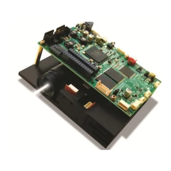
Texas Instruments DLP LightCrafter 4500 Manuals
Manuals and User Guides for Texas Instruments DLP LightCrafter 4500. We have
2
Texas Instruments DLP LightCrafter 4500 manuals available for free PDF download: User Manual, Programming Manual
Texas Instruments DLP LightCrafter 4500 User Manual (76 pages)
Brand:
Texas Instruments
| Category:
Motherboard
| Size: 8 MB
Table of Contents
Table of Contents
2
Preface
6
DLP Lightcrafter 4500 Evaluation Module (EVM)
6
Connectors
7
DLP Lightcrafter 4500 Module Overview
9
Welcome
9
What Is in the Lightcrafter 4500 EVM
9
Light Engine
10
DLP Lightcrafter 4500 Block Diagram
10
Iview Light Engine
11
DLP Lightcrafter Light Engine Specifications
11
Inch DMD Diamond Pixel Geometry
12
Inch DMD Diamond Pixel Array Configuration
12
Diamond Pixel for Vertical, Horizontal, and Diagonal Lines
12
Driver Board
13
DLP Lightcrafter 4500 Driver Board Block Diagram
13
Embedded Processor Interface
14
Other Items Needed for Operation
14
DLP Lightcrafter 4500 Connections
15
DLP Lightcrafter 4500 Connectors (Top View)
16
DLP Lightcrafter 4500 Connectors (Back-Side View)
16
DLP Lightcrafter 4500 Jumpers
17
DLP Lightcrafter 4500 Jumper Locations
17
DLP Lightcrafter 4500 J10 and J12 Voltage Jumpers
18
DLP Lightcrafter 4500 J13 and J15 Voltage Jumpers
18
Dimensions
19
DLP Lightcrafter 4500 Dimensions
20
Quick Start
22
Power-Up the DLP Lightcrafter 4500
22
Operating the DLP Lightcrafter 4500
24
DLP Lightcrafter 4500 Software
24
PC Software
24
System Status
25
DLP Lightcrafter 4500 GUI - Video Mode
25
Operating Mode
26
Image Orientation
27
LED Current Settings
28
Typical Red LED Current and Illuminance Based on PWM Values
28
Typical Green LED Current and Illuminance Based on PWM Values
28
Typical Blue LED Current and Illuminance Based on PWM Values
28
Video Mode
29
Pattern Sequence Mode
30
Sequence Settings
30
DLP Lightcrafter 4500 GUI - Pattern Sequence Mode
31
Pattern Sequence Mode: Start, Pause, Stop
34
Sequence Settings [Variable Exposure]
35
Image Load Timing
36
Pattern Sequence Mode - Variable Exposure
36
Trigger Controls
37
Image Load Timing
37
Trigger Control Subtab
38
LED Delay Control
39
VSYNC Pattern Trigger Mode
39
External Pattern Trigger Mode
39
Firmware Upgrade
40
LED Delay Control Subtab
40
Storing Images in Flash Memory
41
Firmware Upgrade Tab
41
Create Images Tab
42
Firmware Builder
43
Peripheral Control
44
Peripheral Control Tab
44
Pattern Sequences
46
Pattern Sequence Background
46
Relationship between Bit-Planes and 24-Bit RGB Images
46
Bit Partition
46
DLPC350 Internal Memory Buffer
47
Frame Delay between Parallel Interface Input and Projection Output
48
Image Load Time and Pattern Sequence Timing
48
Allowable Pattern Combinations
49
Saving Solutions
51
Applying Solutions
51
Changing Default Solutions
51
Modifying .Ini Files
51
Available Parameters
51
List of Available Parameters When Saving Solutions
52
Save Solution Button
53
Manual Editing
54
LUT Entry Helper Tool
54
Image LUT Entries Example
54
Pandaboard Interface
56
Pandaboard 4500
56
DLP Lightcrafter 4500 to Pandaboard Interface
57
DLP Lightcrafter 4500 with Pandaboard 4500
57
Block Diagram of the Pandaboard Interface
58
J1 Pandaboard 4500 to DLP Lightcrafter 4500 Interface
58
J3 Pandaboard 4500 to DLP Lightcrafter 4500 Interface
59
J4 Pandaboard 4500 to DLP Lightcrafter 4500 Interface
60
J6 Pandaboard 4500 to DLP Lightcrafter 4500 Interface
60
Pandaboard Software
61
Input Trigger Connector Pins
64
Output Trigger Connector Pins
64
UART Connector Pins
65
C0 Connector Pins
65
C1 Connector Pins
65
Fan Connector Pins
66
Red LED Connector Pins
66
Green LED Connector Pins
67
Blue LED Connector Pins
67
FPD-Link Connector Pins
67
JTAG Boundary Scan Connector Pins
68
Power Connector Pins
68
A Safety
72
Power Supply Requirements
72
Important Notice
75
Advertisement
Texas Instruments DLP LightCrafter 4500 Programming Manual (20 pages)
Brand:
Texas Instruments
| Category:
Motherboard
| Size: 2 MB
Table of Contents
Table of Contents
1
Overview
2
Software Installation
2
JTAG Boundary Scan Cable
3
UM232H to Molex 51021-0600 Connections
3
Flash Programming Procedure
4
J30 Location on the DLP Lightcrafter 4500
4
J30 Populated on the DLP Lightcrafter 4500
4
Power Supply Connected to the DLP Lightcrafter 4500
5
JTAG Cable Connected to the DLP Lightcrafter 4500
5
JTAG Flash Programmer First Run
6
Board File Selection in Flash Programmer Tool
7
Firmware File Selection in Flash Programmer Tool
8
Firmware File Size Selection in Flash Programmer Tool
9
JTAG Chain Detection in Flash Programmer Tool
10
Erase Button in Flash Programmer Tool
11
Flash Memory Block Selection and Erase Button
12
Flash Memory Block Erase Completed and Exit Button
13
Program Button in Flash Programming Tool
14
Power and JTAG Cable Removed from the DLP Lightcrafter 4500
15
Lightcrafter 4500 GUI Firmware Upload Window
16
Starting the Lightcrafter 4500 Firmware File Upload Process
17
Troubleshooting
18
Advertisement
Related Products
Texas Instruments DLP LightCrafter Display 4710 EVM
Texas Instruments DLP LightCrafter Display 4710
Texas Instruments DLP LightCrafter Display 3010
Texas Instruments DLP LightCrafter
Texas Instruments DLP LightCrafter Display 3310
Texas Instruments DLP LightCrafter 6500
Texas Instruments DLP LightCrafter 9000
Texas Instruments DLP LightCrafter Dual DLPC900
Texas Instruments DLP LightCrafter DLPC910
Texas Instruments DLP LightCrafter 160CP
Texas Instruments Categories
Motherboard
Control Unit
Microcontrollers
Computer Hardware
Calculator
More Texas Instruments Manuals
Login
Sign In
OR
Sign in with Facebook
Sign in with Google
Upload manual
Upload from disk
Upload from URL