Texas Instruments DLP LightCrafter Single DLPC900 User Manual
Hide thumbs
Also See for DLP LightCrafter Single DLPC900:
- Programmer's manual (97 pages) ,
- User manual (66 pages) ,
- Read this first manual (56 pages)

Subscribe to Our Youtube Channel
Related Manuals for Texas Instruments DLP LightCrafter Single DLPC900


Summary of Contents for Texas Instruments DLP LightCrafter Single DLPC900
- Page 1 DLP® LightCrafter™ Single DLPC900 Evaluation Module (EVM) User's Guide User’s Guide Literature Number: DLPU101A DECEMBER 2020 – REVISED APRIL 2022...
-
Page 3: Table Of Contents
Figure 1-1. DLP LightCrafter Single DLPC900 Hardware Components..................Figure 1-2. DLP LightCrafter Single DLPC900 EVM Block Diagram...................9 Figure 1-3. DLP LightCrafter Single DLPC900 EVM Connectors (Top View)................Figure 1-4. Correct J14 and J15 Labels............................ DLPU101A – DECEMBER 2020 – REVISED APRIL 2022 DLP®... - Page 4 Table of Contents www.ti.com Figure 1-5. Incorrect J14 and J15 Labels..........................Figure 1-6. DLP LightCrafter Single DLPC900 EVM Trigger Voltage Level Selectors.............. Figure 1-7. Flex Cable Diagram..............................15 Figure 2-1. Pattern Mode Panel..............................19 Figure 2-2. Simple Three Pattern Sequence..........................Figure 3-1. DLP LightCrafter DLPC900 GUI..........................22...
-
Page 5: Read This First
All trademarks are the property of their respective owners. About This Guide This guide explains the hardware and software features of the DLP LightCrafter Single DLPC900 EVM systems. The EVM architecture and connectors are described along with a quick start guide on how to operate the DLP LightCrafter Single DLPC900 EVM using a Graphical User Interface (GUI). -
Page 6: Related Documentation From Texas Instruments
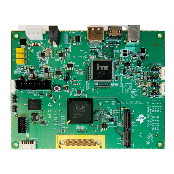
Read This First www.ti.com Figure 1-1. DLP LightCrafter Single DLPC900 Evaluation Module Related Documentation from Texas Instruments Component datasheets, technical documents, design documents, and ordering information can be found at the following links: DLPC900 Digital Controller Product Folder DLPC900 Programmer's Guide... -
Page 7: Dlp Lightcrafter Single Dlpc900 Evm Overview
DLP LightCrafter Single DLPC900 EVM Overview 1.1 Welcome The DLP LightCrafter Single DLPC900 EVM, coupled to a supported Single Controller DMD EVM allows for easy evaluation of the DLP LightCrafter subsystem in bringing together high resolution display and advanced pattern control which is well suited for: •... -
Page 8: Dlp Lightcrafter Single Dlpc900 Evaluation Module (Evm) Hardware
1.2 DLP LightCrafter Single DLPC900 Evaluation Module (EVM) Hardware The DLP LightCrafter Single DLPC900 EVM is one half of a complete DMD imaging electronics subsystem. The DLP LightCrafter Single DLPC900 EVM consists of the single DLPC900 board which includes a single DLPC900 Digital Controller, a digital video receiver, flash memory, power management circuits, and supporting digital logic. -
Page 9: Evm Board
DLP LightCrafter Single DLPC900 EVM Overview 1.3 EVM Board The DLP LightCrafter Single DLPC900 EVM contains the electronics capable of controlling supported Single controller DMDs. The EVMs offer several interface options, USB, I C, trigger inputs and outputs, with video inputs through HDMI or Display Port connectors. -
Page 10: Other Items Needed For Operation
1.4 Other Items Needed for Operation The DLP LightCrafter Single DLPC900 EVM is a flexible, ready-to-use evaluation module which, when coupled to one of the DLP LightCrafter DMD EVMs, enables the sending of customer created patterns from the DLPC900 Controllers to the attached DMD for display at the customer determined pattern rates. -
Page 11: Dlp Lightcrafter Single Dlpc900 Connections
Note: Power supply (and cable), USB cable, and display cable are NOT included with the module. J6 J5 Figure 1-3. DLP LightCrafter Single DLPC900 EVM Connectors (Top View) Table 1-1. DLP LightCrafter Single DLPC900 EVM Connector Reference Connector... -
Page 12: Figure 1-4. Correct J14 And J15 Labels
DLP LightCrafter Single DLPC900 EVM Overview www.ti.com Table 1-1. DLP LightCrafter Single DLPC900 EVM Connector Reference (continued) Connector EVM Function Description or Use Reference Host USB interface DLPC900 USB interface for Host communications with DLPC900 TI use only; Used for debugging DLPC900 ARM software code, requires the ARM RVI ARM RVI ICE debugger ICE debugger. - Page 13 DLP LightCrafter Single DLPC900 EVM Overview Table 1-1. DLP LightCrafter Single DLPC900 EVM Connector Reference (continued) Connector EVM Function Description or Use Reference • Pins 1, 2, and 3 are 12 V. • Pin 5 is Red LED Enable output.
- Page 14 DLP LightCrafter Single DLPC900 EVM Overview www.ti.com 1.5.2 DLP LightCrafter Single DLPC900 Trigger Input and Output Voltage Selectors The trigger inputs on J20 are inputs from external devices to control the pattern sequence. While trigger input 2 is high, trigger input 1 advances the pattern sequence to the next pattern in the sequence on every pulse.
-
Page 15: Dlp Lightcrafter Single Dlpc900 Evm Flex Cable
DLP LightCrafter Single DLPC900 EVM Overview 1.6 DLP LightCrafter Single DLPC900 EVM Flex Cable Electrical malfunctions can occur by stressing the flex cable connecting the DMD circuit board to the DLPC900 controller circuit board. Stressing the flex cable can be caused by: •... - Page 16 DLP LightCrafter Single DLPC900 EVM Overview www.ti.com This page intentionally left blank. DLP® LightCrafter™ Single DLPC900 Evaluation Module (EVM) User's Guide DLPU101A – DECEMBER 2020 – REVISED APRIL 2022 Submit Document Feedback Copyright © 2022 Texas Instruments Incorporated...
-
Page 17: Quick Start
4. After 5 seconds, the DLPC900 device starts sending a built-in rotating pattern sequence of images to the DMD for display on the DMD. 5. Connect a USB cable from a PC to connector J7 on the DLP LightCrafter Single DLPC900 EVM, as seen Figure 1-3. -
Page 18: Creating A Simple Pattern Sequence
Green indicating the connection was successful. The GUI software includes sample images for the DLP LightCrafter Single DLPC900 EVM that are used in the examples in this guide. If the sample image files have not been unzipped during the installation process, then within the GUI install directory, unzip the image files to gain access to all the sample images. - Page 19 Quick Start Figure 2-1. Pattern Mode Panel DLPU101A – DECEMBER 2020 – REVISED APRIL 2022 DLP® LightCrafter™ Single DLPC900 Evaluation Module (EVM) User's Guide Submit Document Feedback Copyright © 2022 Texas Instruments Incorporated...
- Page 20 Quick Start www.ti.com Figure 2-2. Simple Three Pattern Sequence DLP® LightCrafter™ Single DLPC900 Evaluation Module (EVM) User's Guide DLPU101A – DECEMBER 2020 – REVISED APRIL 2022 Submit Document Feedback Copyright © 2022 Texas Instruments Incorporated...
-
Page 21: Operating The Dlp Lightcrafter Single Dlpc900 Evm
Operating the DLP LightCrafter Single DLPC900 EVM Chapter 3 Operating the DLP LightCrafter Single DLPC900 This chapter introduces the Windows software provided with the DLP LightCrafter Single DLPC900 EVM. 3.1 DLP LightCrafter Single DLPC900 Control Software DLPC900REF-SW bundle includes a QT-based GUI application to control the modules through the USB interface. -
Page 22: Pc Software
Operating the DLP LightCrafter Single DLPC900 EVM www.ti.com 3.2 PC Software Upon execution of the DLP LightCrafter DLPC900 GUI application, the panel shown in Figure 3-1 is displayed. The GUI panel contains the following three sections: • System common controls and status on the left. -
Page 23: System Common Controls
Figure 3-2. High DPI Settings 3.3 System Common Controls The DLP LightCrafter Single DLPC900 EVM communicates with the DLPC900 using USB 1.1. The DLPC900 enumerates as a USB device with HID Support. The PC polls all the HID peripherals and once the PC detects the DLPC900, the Connected radio-button changes to green. - Page 24 The GUI queries the DLP LightCrafter Single DLPC900 EVM to determine the DMD type the firmware is programed for and is expecting to be connected to the DLP LightCrafter Single DLPC900 EVM. The indicators in the Chipset Type group box are updated to show which DLPC900 compatible DMDs is connected.
- Page 25 DLP LightCrafter Single DLPC900 EVM is set to Video Mode and the vertical back-porch timing is too small. The error can also occur if the DLP LightCrafter Single DLPC900 EVM is set to Video Pattern Mode where the patterns are from the video port and the pattern sequence timings do not match the video port VSYNC - specifically the cumulative exposure times are greater than the frame time.
-
Page 26: System Settings
Operating the DLP LightCrafter Single DLPC900 EVM www.ti.com 3.4 System Settings Click the System Settings button at the top of the GUI to display the System Settings panel shown in Figure 3-3. Figure 3-3. System Settings Panel Within the System Settings panel, the user can control the orientation of the image, the LEDs, and the optical inversion. - Page 27 Operating the DLP LightCrafter Single DLPC900 EVM Note DLP LightCrafter Single DLPC900 EVMs do not come with LEDs or optical engines of any kind. • Pattern Display Invert Data – This setting allows the user to invert the data to the DMD. The setting must be set before any Pattern LUT updates are sent to the DLPC900 and the pattern sequence must be in the stopped state.
-
Page 28: Video Mode
Input Port Data Swap – Depending on the routing of the parallel RGB data lines, it may be necessary to swap the order of the color channels. The DLP LightCrafter Single DLPC900 EVM require ABC->BAC setting. ABC corresponded to RGB; therefore, the settings mentioned previously means that channels RG are swapped. - Page 29 Programmer's Guide for further information 3.5.1 Video Support Please refer to the DMD data sheet of the DMD connected to the DLP LightCrafter Single DLPC900 EVM for supported video frame rates. DLPU101A – DECEMBER 2020 – REVISED APRIL 2022 DLP® LightCrafter™ Single DLPC900 Evaluation Module (EVM) User's Guide Submit Document Feedback Copyright ©...
-
Page 30: Pattern Modes
Operating the DLP LightCrafter Single DLPC900 EVM www.ti.com 3.6 Pattern Modes Click the Pattern Mode button at the top of the GUI to display the Pattern Mode panel as shown in Figure 3-6. The Pattern Mode panel allows the user to create a pattern sequence. First the user must choose the operating mode by selecting which of the three pattern modes to use. - Page 31 Operating the DLP LightCrafter Single DLPC900 EVM 3.6.1 Menu Bar The Menu bar has six controls as shown in Figure 3-7. • The Save button allows the current pattern design to be saved to a file. • The Load button allows a saved design to be loaded into the Design Panel. This control also allows images to be loaded from a text file that contains a list of the bitmaps in a desired order.
- Page 32 Operating the DLP LightCrafter Single DLPC900 EVM www.ti.com Figure 3-8. Add From List Figure 3-9. Pattern Sequence DLP® LightCrafter™ Single DLPC900 Evaluation Module (EVM) User's Guide DLPU101A – DECEMBER 2020 – REVISED APRIL 2022 Submit Document Feedback Copyright © 2022 Texas Instruments Incorporated...
- Page 33 Operating the DLP LightCrafter Single DLPC900 EVM 4. Each pattern in the display can now be selected individually or a multiple selection can be done. To select multiple patterns in a series, use Shift+Click. To select multiple patterns that are not in a series, use Ctrl+Click.
- Page 34 Operating the DLP LightCrafter Single DLPC900 EVM www.ti.com 12. To stop the pattern sequence, click the Stop button. To restart the pattern sequence click the Start button. The pattern sequence starts from the beginning whenever the pattern sequence is stopped using the Stop button.
- Page 35 Operating the DLP LightCrafter Single DLPC900 EVM 3.6.4 Reordering a Pattern Sequence using the Edit LUT Feature The Edit LUT feature is only available in Pre-Stored Pattern Mode and Pattern On-The-Fly Mode when using GUI 4.0 or later in conjunction with Firmware 5.0 or later. This feature allows the user to manipulate the pattern display sequence without having to reload or change any data in the DLPC900 memory.
- Page 36 Operating the DLP LightCrafter Single DLPC900 EVM www.ti.com Figure 3-12. LUT Editor Panel The following steps detail an example using the Edit LUT feature with five patterns in Pattern On-The-Fly-Mode: 1. By following the steps similar to Section 3.6.2, load five patterns in Pattern On-The-Fly-Mode as shown in Figure 3-11.
- Page 37 Operating the DLP LightCrafter Single DLPC900 EVM 17. Click the Stop button to stop the pattern sequence. 18. Click the Back button to return to the Pattern Mode tab. Note When using the GUI interface, each pattern carries several items of information corresponding to the slot that it was inserted in the original LUT order.
- Page 38 Operating the DLP LightCrafter Single DLPC900 EVM www.ti.com The unwanted trigger behavior can be compensated for by one the following methods: • Method 1: Consider Pattern 2 and 3 ("Sue" and "Matt") as a set that must always be moved together in your new display order.
- Page 39 Operating the DLP LightCrafter Single DLPC900 EVM Figure 3-14. Video Pattern Mode DLPU101A – DECEMBER 2020 – REVISED APRIL 2022 DLP® LightCrafter™ Single DLPC900 Evaluation Module (EVM) User's Guide Submit Document Feedback Copyright © 2022 Texas Instruments Incorporated...
- Page 40 Operating the DLP LightCrafter Single DLPC900 EVM www.ti.com 3.6.6 Creating a Pattern Sequence With DMD Block Load Creating pattern sequences with DMD Block Load achieves higher pattern rates by using a subset of the DMD blocks. See DMD Block Load command in the DLPC900 Software Programmer’s Guide (DLPU018) for a description of this command.
- Page 41 Operating the DLP LightCrafter Single DLPC900 EVM Figure 3-15. DMD Block Load Pattern Sequence DLPU101A – DECEMBER 2020 – REVISED APRIL 2022 DLP® LightCrafter™ Single DLPC900 Evaluation Module (EVM) User's Guide Submit Document Feedback Copyright © 2022 Texas Instruments Incorporated...
- Page 42 Operating the DLP LightCrafter Single DLPC900 EVM www.ti.com 3.6.7 Pattern Settings To configure the output or input triggers click the Pattern Settings button as shown in Figure 3-16. Within this panel, the user can select the output delays of Trigger 1 and 2 and the input delay for Trigger In 1 and 2. The output delays are from the start of the pattern on the DMD.
- Page 43 Operating the DLP LightCrafter Single DLPC900 EVM Figure 3-16. Pattern Settings Panel DLPU101A – DECEMBER 2020 – REVISED APRIL 2022 DLP® LightCrafter™ Single DLPC900 Evaluation Module (EVM) User's Guide Submit Document Feedback Copyright © 2022 Texas Instruments Incorporated...
-
Page 44: Batch Files
Operating the DLP LightCrafter Single DLPC900 EVM www.ti.com 3.7 Batch Files Click the Batch Files button at the top of the GUI to display the Batch Command Sequence panel as shown Figure 3-17. If the Enable Command Logging box is checked, the panel displays all the commands the user clicks on the GUI. - Page 45 Operating the DLP LightCrafter Single DLPC900 EVM Note If an "IDX" error is received during execution of a batch file, this indicates that execution failed at the line number that follows IDX in the error message. POWER_CONTROL commands often result in an IDX error since the EVM can no longer communicate with the GUI because the power state has been changed.
- Page 46 Operating the DLP LightCrafter Single DLPC900 EVM www.ti.com 3.7.2 Creating and Saving Batch Files There are two methods to create and save batch files: • Use the GUI • Use a text editor 3.7.2.1 Creating and Saving a Batch File Using the GUI This example contains the following set of commands: 1.
- Page 47 Operating the DLP LightCrafter Single DLPC900 EVM Figure 3-18. Batch File Example 3.7.2.2 Creating a Batch File Using a Text Editor Use a text editor to add the same three commands in the previous example. Refer to Appendix B in the DLPC900 Programmer’s Guide for the list of command descriptors supported by the DLPC900.
- Page 48 Operating the DLP LightCrafter Single DLPC900 EVM www.ti.com 3.7.4 Adding a Batch File to the Firmware A batch file can be added to the firmware to be used as the default batch file to be executed during the power-up sequence of the DLPC900. Or a batch file can be added to be executed at any time after the power-up sequence has completed to perform some action.
-
Page 49: Peripherals
Operating the DLP LightCrafter Single DLPC900 EVM 3.8 Peripherals Click the Peripherals button at the top of the GUI to display the Peripherals panel as shown in Figure 3-19. Figure 3-19. Peripherals Panel • The I C group box allows external I C device to be controlled using one of the DLPC900 I C interfaces. -
Page 50: Firmware
Operating the DLP LightCrafter Single DLPC900 EVM www.ti.com 3.9 Firmware Click the Firmware button to display the Firmware panel as shown in Figure 3-20. In this panel a user can update the firmware with patterns, batch files, and set start-up conditions. - Page 51 Operating the DLP LightCrafter Single DLPC900 EVM Figure 3-20. Firmware Panel 3.9.1 Adding or Removing Patterns from the Firmware For most efficient storage and compression of images, the GUI packs the images into groups of 24-bit RGB bitmap images. If there are 1-bit black and white images, 8-bit gray scale images, or any other image bit-depth (up to 24-bit images), they are combined to create a composite image.
- Page 52 Operating the DLP LightCrafter Single DLPC900 EVM www.ti.com The DLPC900 Single Controller LightCrafter EVMs are pre-loaded with a pattern sequence that is displayed when power is applied to the EVMs. Since the GUI does not know the images that are stored in flash memory, it is advisable to delete all images from flash before storing new ones.
- Page 53 Operating the DLP LightCrafter Single DLPC900 EVM 3.9.1.2 Adding Images The bitmap images to be added to the firmware file must have the native resolution of the DMD that is being used. The GUI returns an error if it encounters an incorrect image size. Please be sure any images you add to the firmware are of the correct resolution.
- Page 54 Operating the DLP LightCrafter Single DLPC900 EVM www.ti.com Follow these steps to edit the image index and bit position of the images to be used for the pattern sequence. 1. Stop the pattern sequence if it is currently running. 2. Delete all images except for the first two in the Pattern Design panel. See Figure 3-10.
- Page 55 Operating the DLP LightCrafter Single DLPC900 EVM Figure 3-22. Updating the Index and Bit Position DLPU101A – DECEMBER 2020 – REVISED APRIL 2022 DLP® LightCrafter™ Single DLPC900 Evaluation Module (EVM) User's Guide Submit Document Feedback Copyright © 2022 Texas Instruments Incorporated...
- Page 56 Operating the DLP LightCrafter Single DLPC900 EVM www.ti.com 3.9.1.3 Adding Both Images and Batch Files This section covers how to add pattern images and a batch file to the firmware. These steps allow the user to add patterns to the flash and have them automatically uploaded to the DLPC900 upon power up. The GUI is not connected when starting this process.
-
Page 57: Flash Device Parameters
Operating the DLP LightCrafter Single DLPC900 EVM 3.10 Flash Device Parameters For EVM use with several different flash memory parts, the user can edit the FlashDeviceParameters.txt file to match the flash memory part that has been installed with the EVM. This file is located in the DLPC900REF- SW-x.x.x\DLPC900REF-GUI\Flash directory of the... -
Page 58: Jtag Flash Programming
Operating the DLP LightCrafter Single DLPC900 EVM www.ti.com 3.11 JTAG Flash Programming The DLPC900 JTAG Programmer Tool is included in the DLPC900REF-SW bundle allowing a user to program the bootloader image into the flash using the JTAG boundary scan connector if, for example, the bootloader becomes corrupted and the board is rendered inoperable. - Page 59 Choose the driver found in the CDM WHQL Certified zip folder and allow driver installation to complete. Install a jumper at J9 and J11 on the DLP LightCrafter Single DLPC900 EVM. Connect the JTAG signals at J10 on the DLP LightCrafter Single DLPC900 EVM to the UM232H module as shown in Figure 3-25.
- Page 60 Operating the DLP LightCrafter Single DLPC900 EVM www.ti.com This page intentionally left blank. DLP® LightCrafter™ Single DLPC900 Evaluation Module (EVM) User's Guide DLPU101A – DECEMBER 2020 – REVISED APRIL 2022 Submit Document Feedback Copyright © 2022 Texas Instruments Incorporated...
-
Page 61: Connectors
Connectors This chapter describes the connector pins of the DLP LightCrafter Single DLPC900 EVM. 4.1 Input Trigger Connectors The input trigger connector J20 on the DLP LightCrafter Single DLPC900 EVM pins are listed in Table 4-1. The trigger inputs have hysteresis. Two matching six-pin, 1.25-mm connector part numbers are: •... -
Page 62: Dlpc900 Uart
Connectors www.ti.com 4.3 DLPC900 UART The UART output connector J6 on the DLP LightCrafter Single DLPC900 EVM is shown in Table 4-3 and is used solely for debug message output to a terminal. The TX out is 3.3 V TTL level and requires on external transceiver to convert the TTL level signals to RS232. -
Page 63: Dlpc900 I C Port
3.3 V 3.3 V Ground Ground 4.8 GPIO and PWM The GPIO and PWM connector J12 on the DLP LightCrafter Single DLPC900 EVM pins are listed in Table 4-8. Two matching 14-pin, 2.00-mm connector part numbers are: • Molex part number: 87832-1420 •... -
Page 64: Power
Ground Ground Ground Ground Ground Ground 4.9 Power The power socket J17 on the DLP LightCrafter Single DLPC900 pins are shown in Table 4-9. Two matching connector part numbers are: • Switchcraft part number: 760 • Digi-Key part number: SC1051-ND Table 4-9. -
Page 65: Power Supply Requirements
Power Supply Requirements Chapter 5 Power Supply Requirements 5.1 External Power Supply Requirements The DLP LightCrafter Single DLPC900 EVM does not include a power supply. The external power supply requirements are: • Nominal voltage: 12-V DC -5%/+10% • Minimum current: 0 A •... - Page 66 Power Supply Requirements www.ti.com This page intentionally left blank. DLP® LightCrafter™ Single DLPC900 Evaluation Module (EVM) User's Guide DLPU101A – DECEMBER 2020 – REVISED APRIL 2022 Submit Document Feedback Copyright © 2022 Texas Instruments Incorporated...
-
Page 67: Safety
LightCrafter DLPC900 EVM board when operating. CAUTION The kit contains ESD-sensitive components. Handle with care to prevent permanent damage. DLPU101A – DECEMBER 2020 – REVISED APRIL 2022 DLP® LightCrafter™ Single DLPC900 Evaluation Module (EVM) User's Guide Submit Document Feedback Copyright © 2022 Texas Instruments Incorporated... -
Page 68: Revision History
Section 3.9.1.1 ................• BOOThold jumper was corrected to J11 (previously shown as J12)..............DLP® LightCrafter™ Single DLPC900 Evaluation Module (EVM) User's Guide DLPU101A – DECEMBER 2020 – REVISED APRIL 2022 Submit Document Feedback Copyright © 2022 Texas Instruments Incorporated... - Page 69 TI products. TI’s provision of these resources does not expand or otherwise alter TI’s applicable warranties or warranty disclaimers for TI products. TI objects to and rejects any additional or different terms you may have proposed. IMPORTANT NOTICE Mailing Address: Texas Instruments, Post Office Box 655303, Dallas, Texas 75265 Copyright © 2022, Texas Instruments Incorporated...
Need help?
Do you have a question about the DLP LightCrafter Single DLPC900 and is the answer not in the manual?
Questions and answers