Texas Instruments DLP LightCrafter Dual DLPC900 EVM User Manual
Hide thumbs
Also See for DLP LightCrafter Dual DLPC900 EVM:
- Programmer's manual (97 pages) ,
- User manual (69 pages) ,
- Read this first manual (56 pages)
Advertisement
Quick Links
www.ti.com
User's Guide
DLP
®
LightCrafter
1 Read This
First........................................................................................................................................................................3
1.1 About This Guide...............................................................................................................................................................
1.2 Related Documentation from Texas Instruments...............................................................................................................
1.3 If You Need Assistance......................................................................................................................................................
2 DLP LightCrafter Dual DLPC900 EVM
2.1 Welcome............................................................................................................................................................................
2.2 DLP LightCrafter Dual DLPC900 Evaluation Module (EVM) Hardware.............................................................................
2.3 EVM
Board.........................................................................................................................................................................6
2.4 Other Items Needed for
2.5 DLP LightCrafter Dual DLPC900 Connections..................................................................................................................
2.6 DLP LightCrafter Dual DLPC900 EVM Flex
2.7 DLP LightCrafter Dual DLPC900 EVM and DMD EVM Assembly...................................................................................
3 Quick
Start.............................................................................................................................................................................13
3.1 Power-up the DLP LightCrafter Dual DLPC900 EVM......................................................................................................
3.2 Creating A Simple Pattern Sequence..............................................................................................................................
4 Operating the DLP LightCrafter Dual DLPC900 EVM........................................................................................................
4.1 DLP LightCrafter Dual DLPC900 Control
4.2 PC Software.....................................................................................................................................................................
4.3 System Common Controls...............................................................................................................................................
4.4 System Settings...............................................................................................................................................................
4.5 Video Mode......................................................................................................................................................................
4.6 Pattern
Modes..................................................................................................................................................................25
4.7 Batch Files.......................................................................................................................................................................
4.8 Peripherals
Panel.............................................................................................................................................................42
4.9 Firmware..........................................................................................................................................................................
4.10 Reprogram Controller Board for a Different Supported
4.11 Flash Device Parameters...............................................................................................................................................
4.12 JTAG Flash Programming..............................................................................................................................................
4.13 Programming an EDID...................................................................................................................................................
4.14 Intel (Altera) FPGA Programming..................................................................................................................................
5
Connectors............................................................................................................................................................................57
5.1 Input Trigger
Connectors..................................................................................................................................................57
5.2 Output Trigger
Connectors...............................................................................................................................................57
5.3 DLPC900 UART Headers................................................................................................................................................
2
5.4 DLPC900 I
C Port 0.........................................................................................................................................................
2
5.5 DLPC900 I
C Port 1.........................................................................................................................................................
2
5.6 DLPC900 I
C Port 2.........................................................................................................................................................
5.7 JTAG Boundary
Scan.......................................................................................................................................................59
5.8 GPIO and PWM...............................................................................................................................................................
5.9 Power...............................................................................................................................................................................
5.10 External Parallel Video Connector.................................................................................................................................
6 Power Supply Requirements...............................................................................................................................................
6.1 External Power Supply Requirements.............................................................................................................................
7 Safety.....................................................................................................................................................................................
7.1 Caution Labels.................................................................................................................................................................
8 Revision History...................................................................................................................................................................
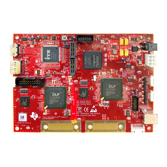
Figure 1-1. DLP LightCrafter Dual DLPC900 Evaluation Module................................................................................................
Figure 2-1. DLP LightCrafter Dual DLPC900 Hardware
Figure 2-2. DLP LightCrafter Dual DLPC900 EVM Block Diagram.............................................................................................
DLPU102C – DECEMBER 2020 – REVISED JULY 2024
Submit Document Feedback
™
Dual DLPC900 Evaluation Module
Table of Contents
Overview..................................................................................................................4
Operation.....................................................................................................................................7
Cable...........................................................................................................11
Software..........................................................................................................17
List of Figures
Components.........................................................................................5
Copyright © 2024 Texas Instruments Incorporated
DMD.........................................................................................53
DLP
®
LightCrafter
Table of Contents
™
Dual DLPC900 Evaluation Module
3
4
4
4
5
7
11
13
14
17
18
19
21
23
38
47
53
54
56
56
58
58
58
59
60
60
60
61
61
61
61
62
3
6
1
Advertisement

Related Manuals for Texas Instruments DLP LightCrafter Dual DLPC900 EVM


Summary of Contents for Texas Instruments DLP LightCrafter Dual DLPC900 EVM
- Page 1 Operation.............................7 2.5 DLP LightCrafter Dual DLPC900 Connections........................2.6 DLP LightCrafter Dual DLPC900 EVM Flex Cable......................11 2.7 DLP LightCrafter Dual DLPC900 EVM and DMD EVM Assembly................... 3 Quick Start.....................................13 3.1 Power-up the DLP LightCrafter Dual DLPC900 EVM...................... 3.2 Creating A Simple Pattern Sequence..........................
- Page 2 Trademarks www.ti.com Figure 2-3. DLP LightCrafter Dual DLPC900 EVM Connectors (Top View).................7 Figure 2-4. DLP LightCrafter Dual DLPC900 EVM Trigger Voltage Level Selectors..............Figure 2-5. Flex Cable Diagram..............................Figure 2-6. DLPLCRC900DEVM Flex Cable Pads........................Figure 2-7. Assembled DLPLCRC900DEVM with DLPLCR90EVM..................
- Page 3 1.1 About This Guide This guide explains the hardware and software features of the DLP LightCrafter Dual DLPC900 EVM systems. The EVM architecture and connectors are described along with a quick start guide on how to operate the DLP LightCrafter Dual DLPC900 EVM using a Graphical User Interface (GUI).
- Page 4 2 DLP LightCrafter Dual DLPC900 EVM Overview 2.1 Welcome The DLP LightCrafter Dual DLPC900 EVM, coupled to one of a number of DLP LightCrafter Dual DLPC900 DMD EVMs, allows for easy evaluation of the DLP LightCrafter subsystem in bringing together high resolution display and advanced pattern control which is well suited for: •...
- Page 5 2.2 DLP LightCrafter Dual DLPC900 Evaluation Module (EVM) Hardware The DLP LightCrafter Dual DLPC900 EVM is one half of a complete DMD imaging electronics subsystem. The EVM consists of the Dual DLPC900 Board which includes two DLPC900 Digital Controllers, a digital video receiver, flash memory, power management circuits, and supporting digital logic.
- Page 6 DLP LightCrafter Dual DLPC900 EVM Overview www.ti.com 2.3 EVM Board The DLP LightCrafter Dual DLPC900 EVM contains the electronics capable of controlling supported Dual controller DMDs. The EVMs offer several interface options, USB, I C, trigger inputs and outputs, with video inputs through HDMI or Display Port connectors.
- Page 7 DLPC900 Controllers to the attached DMD for display at the customer determined pattern rates. The DLP LightCrafter Dual DLPC900 EVM and supported DMD EVMs are offered for purchase separately so that users can determine which elements to piece together for an application evaluation system.
- Page 8 DLP LightCrafter Dual DLPC900 EVM Overview www.ti.com Connector EVM Function Description or Use Reference When pressed resets both DLPC900 controllers. When released, both controllers Hardware Reset Switch boots from reset. Video input to Video Splitter FPGA and DLPC900 controllers. For Video or Video HDMI Input Pattern inputs (primary).
- Page 9 DLP LightCrafter Dual DLPC900 EVM Overview Connector EVM Function Description or Use Reference Set the voltage levels of the Trigger Input 1 signals. Trigger Input 1 voltage level • Jump across pins 1 to 2 for 3.3V selectors. •...
- Page 10 Pin 3 Pin 2 Pin 1 Pin 3 Pin 2 Pin 1 Figure 2-4. DLP LightCrafter Dual DLPC900 EVM Trigger Voltage Level Selectors ® LightCrafter ™ Dual DLPC900 Evaluation Module DLPU102C – DECEMBER 2020 – REVISED JULY 2024 Submit Document Feedback...
- Page 11 The minimum bend radius for forming flex cable (flexible) circuit is 6.35mm Use caution when bending the flex cable to not exceed bending guidelines explained above. 2.7 DLP LightCrafter Dual DLPC900 EVM and DMD EVM Assembly The DLP Dual DLPC900 EVM requires a DMD EVM listed in Section 2.2.
- Page 12 DLP LightCrafter Dual DLPC900 EVM Overview www.ti.com Figure 2-7. Assembled DLPLCRC900DEVM with DLPLCR90EVM ® LightCrafter ™ Dual DLPC900 Evaluation Module DLPU102C – DECEMBER 2020 – REVISED JULY 2024 Submit Document Feedback Copyright © 2024 Texas Instruments Incorporated...
- Page 13 3.1 Power-up the DLP LightCrafter Dual DLPC900 EVM The DLP LightCrafter Dual DLPC900 EVM is ready to use, out of the box, after assembling with one of the supported DMD EVMs. Steps 1 through 6 show how to power, display an image, and connect the EVM to a PC.
- Page 14 Green indicating the connection was successful. The GUI software includes sample images for the DLP LightCrafter Dual DLPC900 EVM that are used in the examples in this guide. If the sample image files have not been unzipped during the installation process, then within the GUI install directory, unzip the image files to gain access to all the sample images.
- Page 15 Quick Start Figure 3-1. Pattern Mode Panel DLPU102C – DECEMBER 2020 – REVISED JULY 2024 ® LightCrafter ™ Dual DLPC900 Evaluation Module Submit Document Feedback Copyright © 2024 Texas Instruments Incorporated...
- Page 16 Quick Start www.ti.com Figure 3-2. Simple Three Pattern Sequence ® LightCrafter ™ Dual DLPC900 Evaluation Module DLPU102C – DECEMBER 2020 – REVISED JULY 2024 Submit Document Feedback Copyright © 2024 Texas Instruments Incorporated...
- Page 17 Operating the DLP LightCrafter Dual DLPC900 EVM 4 Operating the DLP LightCrafter Dual DLPC900 EVM This chapter introduces the Windows software provided with the DLP LightCrafter Dual DLPC900 EVM. 4.1 DLP LightCrafter Dual DLPC900 Control Software DLPC900REF-SW bundle includes a QT-based GUI application to control the modules through the USB interface.
- Page 18 Operating the DLP LightCrafter Dual DLPC900 EVM www.ti.com 4.2 PC Software Upon execution of the DLP LightCrafter DLPC900 GUI application, the panel shown in Figure 4-1 is displayed. The GUI panel contains the following three sections: • System common controls and status on the left.
- Page 19 Operating the DLP LightCrafter Dual DLPC900 EVM Figure 4-2. High DPI Settings 4.3 System Common Controls The DLP LightCrafter DLPC900 GUI communicates with the DLPC900 using USB 1.1. The DLPC900 enumerates as a USB device with HID Support. The PC polls all the HID peripherals and once the PC detects the DLPC900, the Connected radio-button changes to green.
- Page 20 Secondary Present and Ready – The box is checked when the GUI is connected to a DLP LightCrafter Dual DLPC900 EVM. If the GUI is connected to a DLP LightCrafter Dual DLPC900 EVM and the box is not checked, then one or both of the DLPC900s are potentially malfunctioning or the EVM was incorrectly programmed with a Single DLPC900 firmware file.
- Page 21 Operating the DLP LightCrafter Dual DLPC900 EVM - specifically the cumulative exposure times are greater than the frame time. Forced buffer swaps can also occur during any of the pattern modes in preparing a pattern sequence and the timing of a status read. The user needs to perform additional reads of the status to get a correct state of this indicator.
- Page 22 Operating the DLP LightCrafter Dual DLPC900 EVM www.ti.com Within the System Settings panel, the user can control the orientation of the image, the LEDs, and the optical inversion. • Image Orientation – Depending on the orientation of the projected image, the image requires to be flipped on the short or long axis.
- Page 23 Operating the DLP LightCrafter Dual DLPC900 EVM 4.5 Video Mode Click the Video Mode button at the top of the GUI to display the Video Mode panel. Within this panel, there are two tabs: The Source Settings Tab is shown in Figure 4-4.
- Page 24 Sets the level of De-gamma - See the Gamma Configuration and Enable section of the DLPC900 Programmer's Guide for further information. 4.5.1 Video Support Please refer to the DMD data sheet of the DMD connected to the DLP LightCrafter Dual DLPC900 EVM for supported video frame rates. ® LightCrafter ™...
- Page 25 Operating the DLP LightCrafter Dual DLPC900 EVM 4.6 Pattern Modes Click the Pattern Mode button at the top of the GUI to display the Pattern Mode panel as shown in Figure 4-6. The Pattern Mode panel allows the user to create a pattern sequence. First the user must choose the operating mode by selecting which of the three pattern modes to use.
- Page 26 Operating the DLP LightCrafter Dual DLPC900 EVM www.ti.com 4.6.1 Menu Bar The Menu bar has six controls as shown in Figure 4-7. • The Save button allows the current pattern design to be saved to a file. • The Load button allows a saved design to be loaded into the Design Panel. This control also allows images to be loaded from a text file that contains a list of the bitmaps in a desired order.
- Page 27 Operating the DLP LightCrafter Dual DLPC900 EVM Figure 4-9. Pattern Sequence 4. Each pattern in the display can now be selected individually or a multiple selection can be done. To select multiple patterns in a series, use Shift+Click. To select multiple patterns that are not in a series, use Ctrl+Click.
- Page 28 Operating the DLP LightCrafter Dual DLPC900 EVM www.ti.com Figure 4-10. Three Pattern Sequence 8. Select the Repeat radio-button to continuously repeat the pattern sequence, or, if only one time is desired, then select the Play Once radio-button. 9. Click the Update LUT button to upload the pattern sequence definition, including the three pattern images, to the DLPC900.
- Page 29 Operating the DLP LightCrafter Dual DLPC900 EVM 4.6.3 Creating a Pattern Sequence in Pre-Stored Pattern Mode Creating a Pre-Stored Pattern sequence is very similar to Pattern On-The-Fly Mode. The difference is that the patterns are pre-stored in flash memory.
- Page 30 Operating the DLP LightCrafter Dual DLPC900 EVM www.ti.com The LUT Editor panel is shown in Figure 4-12 where the column labeled SNO (for example, Sequence Number) represents the pattern display slot numbers according to the order set (after clicking Update LUT) in the Pattern...
- Page 31 Operating the DLP LightCrafter Dual DLPC900 EVM 14. Notice at the top of the text file is the word Reorder which is required to successfully load a reorder file in the GUI. If desired, swap any of the pattern numbers to create a new pattern sequence and save the file.
- Page 32 Operating the DLP LightCrafter Dual DLPC900 EVM www.ti.com the end. If Pattern 0 (Bob) is placed in front of Pattern 3 (Matt - the triggered pattern), then the last bit-pattern of Pattern 0 (Bob) continues to display in our new display order while waiting for the trigger in Pattern 3 (Matt).
- Page 33 Operating the DLP LightCrafter Dual DLPC900 EVM Figure 4-14 after all settings have been applied. Figure 4-14. Video Pattern Mode DLPU102C – DECEMBER 2020 – REVISED JULY 2024 ® LightCrafter ™ Dual DLPC900 Evaluation Module Submit Document Feedback Copyright © 2024 Texas Instruments Incorporated...
- Page 34 Operating the DLP LightCrafter Dual DLPC900 EVM www.ti.com 4.6.6 Creating a Pattern Sequence With DMD Block Load Creating a pattern sequences with DMD Block Load achieves higher pattern rates by using a subset of the DMD blocks. See DMD Block Load command in the DLPC900 Software Programmer’s Guide (DLPU018) for a description of this command.
- Page 35 Operating the DLP LightCrafter Dual DLPC900 EVM Figure 4-15. DMD Block Load Pattern Sequence DLPU102C – DECEMBER 2020 – REVISED JULY 2024 ® LightCrafter ™ Dual DLPC900 Evaluation Module Submit Document Feedback Copyright © 2024 Texas Instruments Incorporated...
- Page 36 Operating the DLP LightCrafter Dual DLPC900 EVM www.ti.com 4.6.7 Pattern Settings To configure the output or input triggers click the Pattern Settings button as shown in Figure 4-16. Within this panel, the user can select the output delays of Trigger 1 and 2 and the input delay for Trigger In 1 and 2. The output delays are from the start of the pattern on the DMD.
- Page 37 Operating the DLP LightCrafter Dual DLPC900 EVM Figure 4-16. Pattern Settings Panel DLPU102C – DECEMBER 2020 – REVISED JULY 2024 ® LightCrafter ™ Dual DLPC900 Evaluation Module Submit Document Feedback Copyright © 2024 Texas Instruments Incorporated...
- Page 38 Operating the DLP LightCrafter Dual DLPC900 EVM www.ti.com 4.7 Batch Files Click the Batch Files button at the top of the GUI to display the Batch Command Sequence panel as shown in Figure 4-17. If the Enable Command Logging box is checked, then the panel displays all the commands the user clicks on the GUI.
- Page 39 Operating the DLP LightCrafter Dual DLPC900 EVM Note If an IDX error is received during execution of a batch file, then this indicates that execution failed at the line number that follows IDX in the error message. POWER_CONTROL (Power Mode) commands often result in an IDX error since the EVM can no longer communicate with the GUI because the power state has been changed.
- Page 40 Operating the DLP LightCrafter Dual DLPC900 EVM www.ti.com Figure 4-18. Batch File Example 4.7.2.2 Creating a Batch File Using a Text Editor Use a text editor to add the same three commands in the previous example. Refer to Appendix B in the DLPC900 Programmer’s Guide for the list of command descriptors supported by the DLPC900.
- Page 41 9. Click the Browse button and select the firmware files for the EVM being used. Note When updating firmware for the DLP LightCrafter Dual DLPC900 EVM, the GUI creates two firmware files. One for the primary controller and one for the secondary controller. When selecting a firmware file or an updated version, select both of the files named [firmwareimg]-primary.img and [firmwareimg]-...
- Page 42 Operating the DLP LightCrafter Dual DLPC900 EVM www.ti.com 4.8 Peripherals Panel Click the Peripherals button at the top of the GUI to display the Peripherals panel as shown in Figure 4-19. Beginning with GUI 5.3 Peripherals is divided into Figure 4-19 Section 4.8.2.
- Page 43 Operating the DLP LightCrafter Dual DLPC900 EVM 4.8.1 Peripherals Tab Click the Peripherals Tab button at the side of the Peripherals Panel to display the Figure 4-20. Figure 4-20. Peripherals Tab • The I C group box allows external I C device to be controlled using one of the DLPC900 I C interfaces.
- Page 44 Operating the DLP LightCrafter Dual DLPC900 EVM www.ti.com 4.8.2 Debug Tab GUI 5.3 Added debug functions shown in Figure 4-21. Click the Debug Tab button at the side of the Peripherals Panel to display Figure 4-21. Figure 4-21. Debug Tab Selecting the Enable Debug mode checkbox enables the debug functions shown in on the Debug Tab.
- Page 45 Operating the DLP LightCrafter Dual DLPC900 EVM • The Controller Memory Read/Write box allows Reading from and Writing to memory address on either or both controllers. Select the desired controllers in the From box. CAUTION Read from or write only to defined addresses. Reading from or writing to undefined addresses results in unpredictable behavior! There are two virtual interfaces to assist in debugging.
- Page 46 Operating the DLP LightCrafter Dual DLPC900 EVM www.ti.com Max String Length - reads the maximum allocated string size for the debug message Currently Used - reads the string size currently used by the debug message • The Memory Access Batch Files box enables special batch files that can be provided by TI during advanced debugging.
- Page 47 Channels A and B. This feature is a firmware configuration option that only takes effect after uploading the firmware onto the EVM. However, when using the DLP LightCrafter Dual DLPC900 EVM the user can perform a bus swap on both the primary and the secondary by selecting each check box per desired channel.
- Page 48 Operating the DLP LightCrafter Dual DLPC900 EVM www.ti.com Figure 4-23. Firmware Panel 4.9.1 Adding or Removing Patterns from the Firmware For most efficient storage and compression of images, the GUI packs the images into groups of 24-bit RGB bitmap images. If there are 1-bit black and white images, 8-bit gray scale images, or any other image bit-depth (up to 24-bit images), then the images are combined to create a composite image.
- Page 49 9. The GUI displays a pop-up box providing the name of the updated firmware file. Note When updating firmware for the DLP LightCrafter Dual DLPC900 EVM, the GUI creates two firmware files. One for the primary controller and one for the secondary controller. When selecting a firmware file or an updated version, select both of the files named [firmwareimg]-primary.img and [firmwareimg]-...
- Page 50 Note When updating firmware for the DLP LightCrafter Dual DLPC900 EVM, the GUI creates two firmware files. One for the primary controller and one for the secondary controller. When selecting a firmware file or an updated version, select both of the files named [firmwareimg]-primary.img and [firmwareimg]- secondary.img by clicking each while holding the Ctrl key.
- Page 51 Operating the DLP LightCrafter Dual DLPC900 EVM 18. Click the Update LUT button. 19. Click the Start button. 20. All 72 1-bit images are displayed with the settings that were entered in steps 5-8. A possibility is adding many images to the firmware without deleting all the images that are currently in the firmware, and then select which images and bit positions to choose for different pattern sequences.
- Page 52 Operating the DLP LightCrafter Dual DLPC900 EVM www.ti.com Figure 4-24. Pattern LUT Definition and Configuration Figure 4-25. Updating the Index and Bit Position 4.9.1.3 Adding Both Images and Batch Files This section covers how to add pattern images and a batch file to the firmware. These steps allow the user to add patterns to the flash and have them automatically uploaded to the DLPC900 upon power up.
- Page 53 Operating the DLP LightCrafter Dual DLPC900 EVM 4.10 Reprogram Controller Board for a Different Supported DMD To reprogram the controller to support a different DMD, perform the following: 1. With the board powered off, place the boot hold jumper onto the EVM.
- Page 54 Operating the DLP LightCrafter Dual DLPC900 EVM www.ti.com 4.12 JTAG Flash Programming The DLPC900 JTAG Programmer Tool is included in the DLPC900REF-SW bundle allowing a user to program the bootloader image into the flash using the JTAG boundary scan connector if, for example, the bootloader becomes corrupted and the board is rendered inoperable.
- Page 55 Choose the driver found in the CDM WHQL Certified zip folder and allow driver installation to complete. Install a jumper at J10/J12 for the DLP LightCrafter Dual DLPC900 EVM. Populate R118 with a 0 ohm resistor and depopulate R117 near the center of the main board. Connect the JTAG signals at J11 on the DLP LightCrafter...
- Page 56 Operating the DLP LightCrafter Dual DLPC900 EVM www.ti.com 4.13 Programming an EDID The EDID can be programmed through two methods. To program the EDID though HDMI: 1. Remove power from the EVM and install the jumper on J3 and remove jumper on J4 on the EVM to enable the HDMI EDID.
- Page 57 5 Connectors This chapter describes the connector pins of the DLP LightCrafter Dual DLPC900 EVM. 5.1 Input Trigger Connectors The input trigger connector J23 on the DLP LightCrafter Dual DLPC900 EVM pins are listed in Table 5-1. The trigger inputs have hysteresis. Two matching six-pin, 1.25mm connector part numbers are: •...
- Page 58 RTSZ 3.3V Ground 5.4 DLPC900 I C Port 0 The I C_0 connector J14 on the DLP LightCrafter Dual DLPC900 EVM pins are shown in Table 5-4. Two matching four-pin, 1.25mm connector part numbers are: • Molex part number: 51021-0400 •...
- Page 59 3.3V 3.3V supply 3.3V Ground 5.7 JTAG Boundary Scan The JTAG Boundary connector J11 on the DLP LightCrafter Dual DLPC900 EVM pins are listed in Table 5-7. Two matching six-pin, 1.25mm connector part numbers are: • Molex part number: 51021-0600 •...
- Page 60 Connectors www.ti.com 5.8 GPIO and PWM The GPIO and PWM connector J13 on the DLP LightCrafter Dual DLPC900 EVM pins are listed in Table 5-8. Two matching 14-pin, 2.00mm connector part numbers are: • Molex part number: 87832-1420 • Digi-Key part number: WM18641-ND A corresponding mating connector part numbers are: •...
- Page 61 Power Supply Requirements 6 Power Supply Requirements 6.1 External Power Supply Requirements The DLP LightCrafter Dual DLPC900 EVM does not include a power supply. The external power supply requirements are: • Nominal voltage: 12V DC -5%/+10% • Minimum current: 5A •...
- Page 62 Added step 11 and clarified phrasing and the directory of step 3 in Section 4.9.1.2 ........• Updated steps 1 and 2 in Section 4.9.1.3 ....................... ® LightCrafter ™ Dual DLPC900 Evaluation Module DLPU102C – DECEMBER 2020 – REVISED JULY 2024 Submit Document Feedback Copyright © 2024 Texas Instruments Incorporated...
- Page 63 TI products. TI’s provision of these resources does not expand or otherwise alter TI’s applicable warranties or warranty disclaimers for TI products. TI objects to and rejects any additional or different terms you may have proposed. IMPORTANT NOTICE Mailing Address: Texas Instruments, Post Office Box 655303, Dallas, Texas 75265 Copyright © 2024, Texas Instruments Incorporated...
Need help?
Do you have a question about the DLP LightCrafter Dual DLPC900 EVM and is the answer not in the manual?
Questions and answers