Texas Instruments DLP LightCrafter Dual DLPC900 User Manual
Hide thumbs
Also See for DLP LightCrafter Dual DLPC900:
- Programmer's manual (97 pages) ,
- User manual (69 pages) ,
- Read this first manual (56 pages)

Related Manuals for Texas Instruments DLP LightCrafter Dual DLPC900


Summary of Contents for Texas Instruments DLP LightCrafter Dual DLPC900
- Page 1 ® ™ LightCrafter Dual DLPC900 Evaluation Module (EVM) User's Guide User’s Guide Literature Number: DLPU102 DECEMBER 2020...
-
Page 3: Table Of Contents
1.3 EVM Boards..................................1.4 Other Items Needed for Operation........................... 1.5 DLP LightCrafter Dual DLPC900 Connections........................ 1.5.1 DLP LightCrafter Dual DLPC900 LED Enable and PWM Outputs................1.5.2 DLP LightCrafter Dual DLPC900 Trigger Input and Output Voltage Selectors............14 1.6 DLP LightCrafter Dual DLPC900 EVM Flex Cable...................... - Page 4 4.8 GPIO and PWM................................4.9 Power....................................5 Power Supply Requirements............................... 5.1 External Power Supply Requirements..........................6 Safety..................................... 6.1 Caution Labels................................. ® LightCrafter ™ Dual DLPC900 Evaluation Module (EVM) User's Guide DLPU102 – DECEMBER 2020 Submit Document Feedback Copyright © 2020 Texas Instruments Incorporated...
-
Page 5: Read This First
All trademarks are the property of their respective owners. About This Guide This guide explains the hardware and software features of the DLP LightCrafter Dual DLPC900 EVM systems. The EVM architecture and connectors are described along with a quick start guide on how to operate the DLP LightCrafter Dual DLPC900 EVM using a Graphical User Interface (GUI). -
Page 6: Related Documentation From Texas Instruments
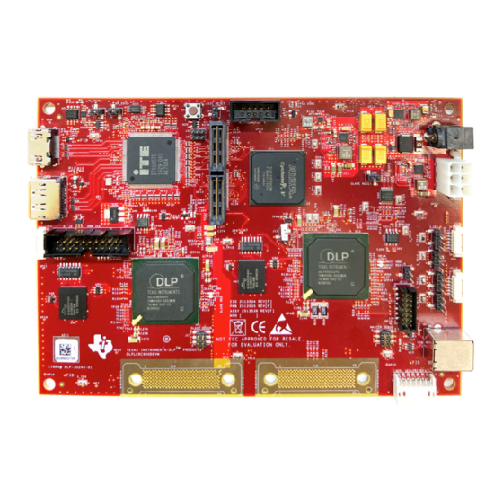
Read This First www.ti.com Figure 1-1. DLP LightCrafter Dual DLPC900 Evaluation Module Related Documentation from Texas Instruments Component datasheets, technical documents, design documents, and ordering information can be found at the following links: DLPC900 Digital Controller Product Folder DLPC900 Programmer's Guide... -
Page 7: Dlp Lightcrafter Dual Dlpc900 Evm Overview
DLP LightCrafter Dual DLPC900 EVM Overview 1.1 Welcome The DLP LightCrafter Dual DLPC900 EVM, coupled to one of a number of DLP LightCrafter Dual DLPC900 DMD EVMs, allows for easy evaluation of the DLP LightCrafter subsystem in bringing together high resolution display and advanced pattern control which is well suited for: •... -
Page 8: Dlp Lightcrafter Dual Dlpc900 Evaluation Module (Evm) Hardware
1.2 DLP LightCrafter Dual DLPC900 Evaluation Module (EVM) Hardware The DLP LightCrafter Dual DLPC900 EVM is one half of a complete DMD imaging electronics subsystem. It consists of the Dual DLPC900 Board which includes two DLPC900 Digital Controllers, a digital video receiver, flash memory, power management circuits, and supporting digital logic. -
Page 9: Evm Boards
DLP LightCrafter Dual DLPC900 EVM Overview 1.3 EVM Boards The DLP LightCrafter Dual DLPC900 EVM contains the electronics capable of controlling supported Dual controller DMDs. The EVMs offer several interface options, USB, I C, trigger inputs and outputs, with video inputs through HDMI or Display Port connectors. - Page 10 DLP LightCrafter Dual DLPC900 EVM Overview www.ti.com The DLP LightCrafter Dual DLPC900 EVM major components are: • A Video Splitter FPGA • Two DLPC900 Digital DMD Controllers • Parallel FLASH memory for storing programming and pattern images for each DLPC900 •...
-
Page 11: Other Items Needed For Operation
DLP LightCrafter Dual DLPC900 EVM Overview 1.4 Other Items Needed for Operation The DLP LightCrafter Dual DLPC900 EVM is a flexible, ready-to-use evaluation module which, when coupled to one of the supported DLP LightCrafter Dual Controller DMD EVMs, enables the sending of customer created patterns from the DLPC900 Controllers to the attached DMD for display at the customer determined pattern rates. -
Page 12: Dlp Lightcrafter Dual Dlpc900 Connections
Note: Power supply (and cable), USB cable, and display cable are NOT included with the module. D9 D8 D7 D6 Figure 1-3. DLP LightCrafter Dual DLPC900 EVM Connectors (Top View) Connector EVM Function Description or Use Reference When pressed resets both DLPC900 controllers. - Page 13 DLP LightCrafter Dual DLPC900 EVM Overview Connector EVM Function Description or Use Reference Master DLPC900 UART interface for debug messages to a terminal • Bits per second: 115200 • Data bits: 8 • Parity: None DLPC900 debug UART (Master •...
-
Page 14: Dlp Lightcrafter Dual Dlpc900 Led Enable And Pwm Outputs
12-V supply to the EVM regulator circuitry and reset the controller. 1.5.2 DLP LightCrafter Dual DLPC900 Trigger Input and Output Voltage Selectors The trigger inputs on J23 are inputs from external devices to control the pattern sequence. While trigger input 2 is high, trigger input 1 advances the pattern sequence to the next pattern in the sequence on every pulse. -
Page 15: Dlp Lightcrafter Dual Dlpc900 Evm Flex Cable
Pin 3 Pin 2 Pin 1 Figure 1-4. DLP LightCrafter Dual DLPC900 EVM Trigger Voltage Level Selectors 1.6 DLP LightCrafter Dual DLPC900 EVM Flex Cable Electrical malfunctions can occur by stressing the flex cable(s) connecting the DMD circuit board to the DLPC900 controller circuit board. - Page 16 DLP LightCrafter Dual DLPC900 EVM Overview www.ti.com This page intentionally left blank. ® LightCrafter ™ Dual DLPC900 Evaluation Module (EVM) User's Guide DLPU102 – DECEMBER 2020 Submit Document Feedback Copyright © 2020 Texas Instruments Incorporated...
-
Page 17: Quick Start
4. After 5 seconds, the two DLPC900 devices start sending a built-in rotating pattern sequence of images to the DMD for display on the DMD. 5. Connect a USB cable from a PC to connector J8 on the DLP LightCrafter Dual DLPC900 EVM, as seen in Figure 1-3. -
Page 18: Creating A Simple Pattern Sequence
Green indicating the connection was successful. The GUI software includes sample images for the DLP LightCrafter Dual DLPC900 EVM that are used in the examples in this guide. If the sample image files have not been unzipped during the installation process, then within the GUI install directory, unzip the image files to gain access to all the sample images. - Page 19 Quick Start Figure 2-1. Pattern Mode Panel DLPU102 – DECEMBER 2020 ® LightCrafter ™ Dual DLPC900 Evaluation Module (EVM) User's Guide Submit Document Feedback Copyright © 2020 Texas Instruments Incorporated...
- Page 20 Quick Start www.ti.com Figure 2-2. Simple Three Pattern Sequence ® LightCrafter ™ Dual DLPC900 Evaluation Module (EVM) User's Guide DLPU102 – DECEMBER 2020 Submit Document Feedback Copyright © 2020 Texas Instruments Incorporated...
-
Page 21: Operating The Dlp Lightcrafter Dual Dlpc900 Evm
Operating the DLP LightCrafter Dual DLPC900 EVM Chapter 3 Operating the DLP LightCrafter Dual DLPC900 EVM This chapter introduces the Windows software provided with the DLP LightCrafter Dual DLPC900 EVM. 3.1 DLP LightCrafter Dual DLPC900 Control Software DLPC900REF-SW bundle includes a QT-based GUI application to control the modules through the USB interface. -
Page 22: Pc Software
Operating the DLP LightCrafter Dual DLPC900 EVM www.ti.com 3.2 PC Software Upon execution of the DLP LightCrafter DLPC900 GUI application, the panel shown in Figure 3-1 is displayed. The GUI panel contains the following three sections: • System common controls and status on the left. -
Page 23: System Common Controls
Operating the DLP LightCrafter Dual DLPC900 EVM Note If the text in the GUI does not display correctly please change the DPI settings. Right click on the executable and select Properties. On the Compatibility tab select the "Change high DPI settings"... -
Page 24: Connected Dmd Type
DLP LightCrafter Dual DLPC900 EVM is set to Video Mode and the vertical back-porch timing is too small. The error can also occur if the DLP LightCrafter Dual DLPC900 EVM is set to Video Pattern Mode where the patterns are from the video port and the pattern sequence timings do not match the video port VSYNC - specifically the cumulative exposure times are greater than the frame time. - Page 25 Operating the DLP LightCrafter Dual DLPC900 EVM • Sequence Abort Status Flag – The box is checked whenever a sequence abort has occurred. Sequence abort may occur during any pattern mode in preparing a pattern sequence and the timing of reading the status.
-
Page 26: System Settings
Operating the DLP LightCrafter Dual DLPC900 EVM www.ti.com 3.4 System Settings Click the System Settings button at the top of the GUI to display the System Settings panel shown in Figure 3-3. Figure 3-3. System Settings Panel ® LightCrafter ™... - Page 27 LED currents to have an opposite effect on the LEDs as the current is changed. Note DLP LightCrafter Dual DLPC900 EVMs do not come with LEDs or optical engines of any kind. • Pattern Display Invert Data – This setting allows the user to invert the data to the DMD. The setting must be set before any Pattern LUT updates are sent to the DLPC900 and the pattern sequence must be in the stopped state.
-
Page 28: Video Mode
Operating the DLP LightCrafter Dual DLPC900 EVM www.ti.com 3.5 Video Mode Click the Video Mode button at the top of the GUI to display the Video Mode panel. Within this panel, there are two tabs: The Source Settings Tab is shown in Video Mode Panel - Source Settings Tab. -
Page 29: Video Support
Sets the level of De-gamma - See the Gamma Configuration and Enable section of the DLPC900 Programmer's Guide for further information. 3.5.1 Video Support Please refer to the DMD data sheet of the DMD connected to the DLP LightCrafter Dual DLPC900 EVM for supported video frame rates. DLPU102 – DECEMBER 2020 ® LightCrafter ™... -
Page 30: Pattern Modes
Operating the DLP LightCrafter Dual DLPC900 EVM www.ti.com 3.6 Pattern Modes Click the Pattern Mode button at the top of the GUI to display the Pattern Mode panel as shown in Figure 3-6. The Pattern Mode panel allows the user to create a pattern sequence. First the user must choose the operating mode by selecting which of the three pattern modes to use. -
Page 31: Menu Bar
Operating the DLP LightCrafter Dual DLPC900 EVM 3.6.1 Menu Bar The Menu bar has six controls as shown in Figure 3-7. • The Save button allows the current pattern design to be saved to a file. • The Load button allows a saved design to be loaded into the Design Panel. This control also allows images to be loaded from a text file that contains a list of the bitmaps in a desired order. - Page 32 Operating the DLP LightCrafter Dual DLPC900 EVM www.ti.com Figure 3-8. Add From List Figure 3-9. Pattern Sequence ® LightCrafter ™ Dual DLPC900 Evaluation Module (EVM) User's Guide DLPU102 – DECEMBER 2020 Submit Document Feedback Copyright © 2020 Texas Instruments Incorporated...
- Page 33 Operating the DLP LightCrafter Dual DLPC900 EVM 4. Each pattern in the display can now be selected individually or a multiple selection can be done. To select multiple patterns in a series, use Shift+Click. To select multiple patterns that are not in a series, use Ctrl +Click.
-
Page 34: Creating A Pattern Sequence In Pre-Stored Pattern Mode
Operating the DLP LightCrafter Dual DLPC900 EVM www.ti.com Another method of creating a pattern sequence in Patten On-The-Fly Mode is using a batch file that contains all the necessary commands and the compressed images. Follow these steps to execute a pattern sequence using a batch file. -
Page 35: Reordering A Pattern Sequence Using The Edit Lut Feature
Operating the DLP LightCrafter Dual DLPC900 EVM 3.6.4 Reordering a Pattern Sequence using the Edit LUT Feature The Edit LUT feature is only available in Pre-Stored Pattern Mode and Pattern On-The-Fly Mode when using GUI 4.0 or later in conjunction with Firmware 5.0 or later. This feature allows the user to manipulate the pattern display sequence without having to reload or change any data in the DLPC900 memory. - Page 36 Operating the DLP LightCrafter Dual DLPC900 EVM www.ti.com The LUT Editor panel is shown in Figure 3-12 where the column labeled “SNO” (i.e. Sequence Number) represents the pattern display slot numbers according to the order set (after clicking Update LUT) in the Pattern...
- Page 37 Operating the DLP LightCrafter Dual DLPC900 EVM 12.Click the Save button to save the new pattern sequence as a text file for later use. Name the file Reorderexample.txt and save it in a directory of choice. 13.Browse to wherever the text file was saved, and open the file in a text editor program as shown in Figure 3-13.
-
Page 38: Creating A Pattern Sequence In Video Pattern Mode
Operating the DLP LightCrafter Dual DLPC900 EVM www.ti.com 3.6.4.1 Special Considerations for Input Triggers when using the Edit LUT Feature Input triggers have some special considerations when using the new Edit LUT Feature. As previously noted, Pattern 3 (“Matt”) has an input trigger associated with it. When a trigger is added to a pattern, the pattern preceding it, Pattern 2 (“Sue”) in this case, has an all-black pattern loaded at the very end of it so that while the... - Page 39 Operating the DLP LightCrafter Dual DLPC900 EVM 12.Remove the check from the Frame Change box. 13.Select pattern 0 only and check the Frame Change box. 14.Click the Update LUT button. 15.Click the Start button to run the sequence. The system displays a green 2-bit sequence based on G0 & G1 for 1215 μs, a red 4-bit sequence based on R0 - R3 for 1215 μs, and a blue 3-bit sequence based on B0 - B2...
-
Page 40: Creating A Pattern Sequence With Dmd Block Load
Operating the DLP LightCrafter Dual DLPC900 EVM www.ti.com 3.6.6 Creating a Pattern Sequence With DMD Block Load Creating a pattern sequences with DMD Block Load achieves higher pattern rates by using a subset of the DMD blocks. See DMD Block Load command in the DLPC900 Software Programmer’s Guide (DLPU018) for a description of this command. - Page 41 Operating the DLP LightCrafter Dual DLPC900 EVM Figure 3-15. DMD Block Load Pattern Sequence DLPU102 – DECEMBER 2020 ® LightCrafter ™ Dual DLPC900 Evaluation Module (EVM) User's Guide Submit Document Feedback Copyright © 2020 Texas Instruments Incorporated...
-
Page 42: Pattern Settings
Operating the DLP LightCrafter Dual DLPC900 EVM www.ti.com 3.6.7 Pattern Settings To configure the output or input triggers click the Pattern Settings button as shown in Figure 3-16. Within this panel, the user can select the output delays of Trigger 1 and 2 and the input delay for Trigger In 1 and 2. The output delays are from the start of the pattern on the DMD. - Page 43 Operating the DLP LightCrafter Dual DLPC900 EVM Figure 3-16. Pattern Settings Panel DLPU102 – DECEMBER 2020 ® LightCrafter ™ Dual DLPC900 Evaluation Module (EVM) User's Guide Submit Document Feedback Copyright © 2020 Texas Instruments Incorporated...
-
Page 44: Batch Files
Operating the DLP LightCrafter Dual DLPC900 EVM www.ti.com 3.7 Batch Files Click the Batch Files button at the top of the GUI to display the Batch Command Sequence panel as shown in Figure 3-17. If the Enable Command Logging box is checked, the panel displays all the commands the user clicks on the GUI. -
Page 45: Creating And Saving Batch Files
Operating the DLP LightCrafter Dual DLPC900 EVM 3.7.2 Creating and Saving Batch Files There are two methods to create and save batch files: • Use the GUI • Use a text editor 3.7.2.1 Creating and Saving a Batch File Using the GUI This example contains the following set of commands: 1. -
Page 46: Loading A Batch File
Operating the DLP LightCrafter Dual DLPC900 EVM www.ti.com Figure 3-18. Batch File Example 3.7.2.2 Creating a Batch File Using a Text Editor Use a text editor to add the same three commands in the previous example. Refer to Appendix B in the DLPC900 Programmer’s Guide for the list of command descriptors supported by the DLPC900. -
Page 47: Adding A Batch File To The Firmware
15.Click the Upload button. The GUI performs the necessary steps to update the firmware in the EVM. Note When updating firmware for the DLP LightCrafter Dual DLPC900 EVM, the GUI creates two firmware files. One for the master controller and one for the slave controller. When selecting a firmware file or an updated version, select both firmwareimg-master.img and firmwareimg-slave.img files by clicking... -
Page 48: Peripherals
Operating the DLP LightCrafter Dual DLPC900 EVM www.ti.com 3.8 Peripherals Click the Peripherals button at the top of the GUI to display the Peripherals panel as shown in Figure 3-19. Figure 3-19. Peripherals Panel • The I C group box allows external I C device to be controlled using one of the DLPC900 I C interfaces. -
Page 49: Firmware
Channels A and B. This feature is a firmware configuration option that only takes effect after uploading the firmware onto the EVM. However, when using the DLP LightCrafter Dual DLPC900 EVM the user may perform a bus swap on both the Master and the Slave by selecting each checkbox per desired channel. -
Page 50: Adding Or Removing Patterns From The Firmware
Operating the DLP LightCrafter Dual DLPC900 EVM www.ti.com Figure 3-20. Firmware Panel 3.9.1 Adding or Removing Patterns from the Firmware For most efficient storage and compression of images, the GUI packs the images into groups of 24-bit RGB bitmap images. This means if there are 1-bit black and white images, 8-bit gray scale images, or any other image bit-depth (up to 24-bit images), they are combined to create a composite image. - Page 51 Operating the DLP LightCrafter Dual DLPC900 EVM The DLP LightCrafter Dual EVM can be loaded with a pattern sequence that is displayed when power is applied to the EVMs. Since the GUI does not know the images that are stored in flash memory, it is advisable to delete all images from flash before storing new ones.
- Page 52 Note When updating firmware for the DLP LightCrafter Dual DLPC900 EVM, the GUI creates two firmware files: one for the master controller and one for the slave controller. When selecting a firmware file or an updated version, select both firmwareimg-master.img and firmwareimg- slave.img files by clicking both files while holding the Ctrl key.
- Page 53 Operating the DLP LightCrafter Dual DLPC900 EVM requires editing the image index and the bit position in the Pattern LUT Definition that is sent to the EVM, and then using the Batch File method to upload the Pattern LUT Definition and Configuration settings to the EVM.
- Page 54 Operating the DLP LightCrafter Dual DLPC900 EVM www.ti.com Figure 3-22. Updating the Index and Bit Position 3.9.1.3 Adding Both Images and Batch Files This section covers how to add pattern images and a batch file to the firmware. These steps allow the user to add patterns to the flash and have them automatically uploaded to the DLPC900 upon power up.
-
Page 55: Flash Device Parameters
Operating the DLP LightCrafter Dual DLPC900 EVM 3.10 Flash Device Parameters For EVM use with several different flash memory parts, the user can edit the FlashDeviceParameters.txt file to match the flash memory part that has been installed with the EVM. This file is located in the DLPC900REF-SW- x.x.x\DLPC900REF-GUI\Flash directory of the... - Page 56 Choose the driver found in the CDM WHQL Certified zip folder and allow driver installation to complete. Install a jumper at J10/J12 for the DLP LightCrafter Dual DLPC900 EVM. Populate R118 with a 0 ohm resistor and depopulate R117 near the center of the main board. Connect the JTAG signals at J11 on the DLP LightCrafter...
-
Page 57: Intel (Altera) Fpga Programming
Operating the DLP LightCrafter Dual DLPC900 EVM Note Make sure that verify is 100% complete! Do the same Erase and Flash for the second DLPC900. Finally remove the UM232H JTAG and remove jumper at J10 & J12, and then cycle the board power to the EVM. Plug in a USB cable between the EVM and the PC and allow the PC to detect the EVM USB connection. - Page 58 Operating the DLP LightCrafter Dual DLPC900 EVM www.ti.com This page intentionally left blank. ® LightCrafter ™ Dual DLPC900 Evaluation Module (EVM) User's Guide DLPU102 – DECEMBER 2020 Submit Document Feedback Copyright © 2020 Texas Instruments Incorporated...
-
Page 59: Connectors
Connectors This chapter describes the connector pins of the DLP LightCrafter Dual DLPC900 EVM. 4.1 Input Trigger Connectors The input trigger connector J23 on the DLP LightCrafter Dual DLPC900 EVM pins are listed in Table 4-1. The trigger inputs have hysteresis. Two matching six-pin, 1.25-mm connector part numbers are: •... -
Page 60: Dlpc900 Uart
3.3 V 3.3 V 4.4 DLPC900 I C Port 0 The I C-0 connector J14 on the DLP LightCrafter Dual DLPC900 EVM pins are shown in Table 4-4. Two matching four-pin, 1.25-mm connector part numbers are: • Molex part number: 51021-0400 •... -
Page 61: Port 2
3.3 V 3.3 V supply 3.3 V Ground 4.7 JTAG Boundary Scan The JTAG Boundary connector J11 on the DLP LightCrafter Dual DLPC900 EVM pins are listed in Table 4-7. Two matching six-pin, 1.25-mm connector part numbers are: • Molex part number: 51021-0600 •... -
Page 62: Gpio And Pwm
Connectors www.ti.com 4.8 GPIO and PWM The GPIO and PWM connector J13 on the DLP LightCrafter Dual DLPC900 EVM pins are listed in Table 4-8. Two matching 14-pin, 2.00-mm connector part numbers are: • Molex part number: 87832-1420 • Digi-Key part number: WM18641-ND A corresponding mating connector part numbers are: •... -
Page 63: Power Supply Requirements
Power Supply Requirements Chapter 5 Power Supply Requirements 5.1 External Power Supply Requirements The DLP LightCrafter Dual DLPC900 EVM does not include a power supply. The external power supply requirements are: • Nominal voltage: 12-V DC -5%/+10% • Minimum current: 0 A •... - Page 64 Power Supply Requirements www.ti.com This page intentionally left blank. ® LightCrafter ™ Dual DLPC900 Evaluation Module (EVM) User's Guide DLPU102 – DECEMBER 2020 Submit Document Feedback Copyright © 2020 Texas Instruments Incorporated...
-
Page 65: Safety
LightCrafter DLPC900 EVM board when operating. CAUTION The kit contains ESD-sensitive components. Handle with care to prevent permanent damage. DLPU102 – DECEMBER 2020 ® LightCrafter ™ Dual DLPC900 Evaluation Module (EVM) User's Guide Submit Document Feedback Copyright © 2020 Texas Instruments Incorporated... - Page 66 TI products. TI’s provision of these resources does not expand or otherwise alter TI’s applicable warranties or warranty disclaimers for TI products. Mailing Address: Texas Instruments, Post Office Box 655303, Dallas, Texas 75265 Copyright © 2020, Texas Instruments Incorporated...
Need help?
Do you have a question about the DLP LightCrafter Dual DLPC900 and is the answer not in the manual?
Questions and answers