TESTO 320 Instruction Manual
Flue gas analyzer
Hide thumbs
Also See for 320:
- Instruction manual (74 pages) ,
- Manual (2 pages) ,
- Instruction manual (74 pages)
Table of Contents
Advertisement
Quick Links
Download this manual
See also:
Instruction Manual
Advertisement
Table of Contents

Subscribe to Our Youtube Channel
Related Manuals for TESTO 320


Summary of Contents for TESTO 320
- Page 1 320 · Flue gas analyzer Instruction manual...
-
Page 3: Table Of Contents
1 Contents Contents Contents ....................3 Safety and the environment ..............6 2.1. About this document ................ 6 2.2. Ensure safety ................... 7 2.3. Protecting the environment .............. 8 Specifications ..................9 3.1. Use ....................9 3.2. Technical data ................10 3.2.1. - Page 4 1 Contents Using the product ................. 33 6.1. Performing settings ............... 33 6.1.1. Assigning the right function key ..............33 6.1.2. Instrument settings ..................33 6.1.2.1. Measurement view ................33 6.1.2.2. Alarm limits ..................35 6.1.2.3. Units ....................35 6.1.2.4. Date / time ..................36 6.1.2.5.
- Page 5 1 Contents Maintaining the product ................ 57 7.1. Cleaning the measuring instrument ..........57 7.2. Replacing the rechargeable battery ..........57 7.3. Charging the battery ..............59 7.4. Replacing sensors ................. 60 7.5. Recalibrating/adjusting sensors ............. 60 7.6. Cleaning the modular flue gas probe ..........61 7.7.
-
Page 6: Safety And The Environment
2 Safety and the environment Safety and the environment 2.1. About this document This document describes testo 320 products with the instrument setting Country version | Germany. > Please read this documentation through carefully and familiarize yourself with the product before putting it to use. Pay particular attention to the safety instructions and warning advice in order to prevent injuries and damage to the products. -
Page 7: Ensure Safety
Use only original spare parts from Testo. > Any further or additional work must only be carried out by authorised personnel. Testo will otherwise refuse to accept responsibility for the proper functioning of the measuring instrument after repair and for the validity of certifications. -
Page 8: Protecting The Environment
> Dispose of faulty rechargeable batteries/spent batteries in accordance with the valid legal specifications. > At the end of its useful life, send the product to the separate collection for electric and electronic devices (observe local regulations) or return the product to Testo for disposal. -
Page 9: Specifications
These systems can be adjusted using the testo 320 and checked for compliance with the applicable limit values. The following tasks can also be carried out with the testo 320: • Regulating the O2, CO and CO2 values in combustion plants for the purpose of ensuring optimal operation. -
Page 10: Technical Data
3 Specifications 3.2. Technical data 3.2.1. Examinations and licenses As declared in the certificate of conformity, this product complies with Directive 2004/108/EC. This product is TÜV-tested in compliance with 1. BImSchV. The sensors 0393 0105 (CO, H2-compensated), 0393 0003 (O2), temperature and pressure are TÜV-tested in accordance with EN 50379 part 2 The measuring cell 0393 0053 (CO, not H2-compensated) is TÜV-... - Page 11 The FCC demands that the user is to be informed that with any changes and modifications to the device, which have not been explicitly approved by testo AG, the right of the user to use this device will become null and void.
-
Page 12: Declaration Of Conformity
3 Specifications 3.2.3. Declaration of Conformity... -
Page 13: Measurement Ranges And Resolution
3 Specifications 3.2.4. Measurement ranges and resolution Measurement Measuring range Resolution parameter 0 to 21 Vol.% 0.1 vol.% 0...4000 ppm 1 ppm CO, H -comp. 0 to 8000 ppm 1 ppm COlow, H -comp. 0 to 500 ppm 0.1 ppm Draught -9.99 to 40.00 hPa 0.01 hPa Fine... -
Page 14: Accuracy And Response Time
3 Specifications 3.2.5. Accuracy and response time Measurement Accuracy Response parameter time (t ±0.2 vol.% < 20 s ±20 ppm (0 to 400 ppm) < 60 s ±5% of meas. val. (401 to 2000 ppm) ±10% of meas. val. (2001 to 4000 ppm) CO, H -comp. -
Page 15: Other Instrument Data
573 g Dimensions 240 x 85 x 65 mm Memory 500 measured values Display Graphic colour display, 240 x 320 pixels Gas leak testing visual indication (LED) probe audible indication by buzzer Optimum rech. batt. Charge level: capacity at 50-80% ambient storage conditions temperature: 10-20°C... - Page 16 O2 sensor: 24 months CO sensor: 24 months CO sensor with H2 comp.: 24 months CO/H2 low sensor (TCHL): 24 months Flue gas probe: 24 months Thermocouple: 12 months Rech. batt.: 12 months Terms of warranty: see website Terms of warranty www.testo.com/warranty...
-
Page 17: Product Description
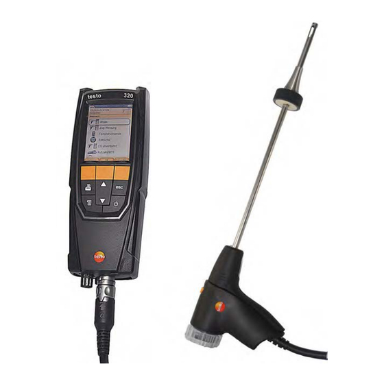
4 Product description Product description 4.1. Measuring instrument 4.1.1. Front view 1 Display 2 Function keys 3 Keypad... -
Page 18: Keypad
Scroll up, increase value, navigate [▼] Scroll down, reduce value, navigate [esc] Back, cancel function Open main menu Transmit data to the Testo protocol printer. 4.1.3. Display 1 Status bar (dark grey background): • Warning symbol (only if there is an instrument error, display of error in instrument diagnosis menu), otherwise: Instrument designation. -
Page 19: Instrument Connections
4 Product description ® • Indication of Bluetooth status, power supply and remaining rechargeable battery capacity: Icon Feature ® blue symbol = Bluetooth ® grey symbol = Bluetooth Battery operation Display of remaining rechargeable battery capacity by colour and fill level of the battery icon (green = 5-100%, red = <... -
Page 20: Condensate Outlet And Interfaces
4 Product description 4.1.5. Condensate outlet and interfaces 1 Infrared interface (IrDA) 2 Bluetooth interface (option) 3 Condensate outlet... -
Page 21: Rear View
4 Product description 4.1.6. Rear view 1 Attachment for carrying strap 2 Condensate trap 3 Magnetic holder CAUTION > Keep a safe distance from products which could be damaged by magnets (e.g. monitors, computers, pacemakers, credit cards). 4 Service lid... -
Page 22: Components
4 Product description 4.1.7. Components 1 Rechargeable battery 2 Measured gas pump 3 Slot for O2 sensor 4 Slot for CO sensor, COlow sensor or CO, H2-compensated sensor... -
Page 23: Compact Flue Gas Probe
4 Product description 4.2. Compact flue gas probe 1 Removable filter chamber with window and particle filter 2 Probe handle 3 Connector plug for measuring instrument 4 Connecting cable 4.3. Modular flue gas probe 1 Removable filter chamber with window and particle filter 2 Lock release 3 Probe module 4 Connector plug for measuring instrument... -
Page 24: First Steps
5 First steps First steps 5.1. Commissioning The measuring instrument is supplied with a rechargeable battery already fitted. > Charge the rechargeable battery fully before using the measuring instrument, see Charging the battery, page 59. 5.2. Getting to know the product 5.2.1. -
Page 25: Connecting Probes
5 First steps 5.2.2. Connecting probes Probe detection at the flue gas socket is carried out continuously. New probes are recognised automatically. Connect a probe to the probe socket before switching on the measuring instrument or start sensor detection → manually after changing the probe: [Options] Sensor... -
Page 26: Switching On
5 First steps 5.2.3. Switching on > Press The start screen is displayed (duration: approx 15 s). During commissioning, when the instrument is switched on, the Country version menu is displayed. Set the country version: → [OK]. 1. Select the country version: [▲], [▼] →... -
Page 27: Printing/Saving Data
5 First steps 3. Set value: [▲], [▼], [◄], [►] (depending on the selected function). 4. Confirm the entry: [OK]. 5. Repeat steps 1 and 4 as required. 6. Save the entry: [Finished]. Input editor 1. Select the value (character) to be changed: [▲], [▼], [◄], [►]. -
Page 28: Saving Data To The Clipboard (Temporary Memory)
5 First steps 5.2.7. Saving data to the clipboard (temporary memory) Using the clipboard, measurement results from various measurement types can be combined to produce a common record, which can then be printed out (see above). Data is saved to the clipboard via the Options menu and the... -
Page 29: Folders / Locations
5 First steps 5.3. Folders / Locations All measuring values can be saved under the currently active location. Measuring values that have not been saved are lost when the measuring instrument is switched off! Folders and locations can be created, edited, copied and enabled. Folders and locations (incl. - Page 30 5 First steps Search → [Edit]. Edit search criteria: [►] → [OK]. Select search criteria: [▲], [▼] Possible options: • Contact person • Folder name • Town/city • Postcode • Street The selected criterion is displayed. 3. Call up entry field for search text: [►] or [▼] >...
-
Page 31: Measurement Records
5 First steps Other location options: → > [Options] Edit location: make changes to an existing location. → > [Options] Copy location: make a copy of an existing location in the same folder. → > [Options] Delete location: delete an existing location. Create a new folder: →... -
Page 32: Instrument Diagnosis
5 First steps 5.5. Instrument diagnosis Important operating values and instrument data are displayed. A gas path check can be carried out. The status of the sensors and any instrument errors not yet rectified can be displayed. Call up function: →... -
Page 33: Using The Product
6 Using the product Using the product 6.1. Performing settings 6.1.1. Assigning the right function key The right function key can have a function from the Options menu assigned to it. The menu Options is accessed via the left function key and is available in many different menus. - Page 34 6 Using the product Oxygen Carbon dioxide Flue gas loss with due consideration of the calorific value range η+ Efficiency with due consideration of the calorific value range Carbon monoxide COunv Carbon monoxide undiluted λ Air ratio COumg Ambient carbon monoxide CO2um Ambient carbon dioxide O2ref...
-
Page 35: Alarm Limits
6 Using the product Options: → > [Options] Number of lines: change the number of measured values per display page. → > [Options] Blank line: insert a blank line in front of the selected line. → > [Options] Delete line: delete the selected line. →... -
Page 36: Date / Time
6 Using the product 6.1.2.4. Date / time Date, time mode and time can be set. Calling up the function: → → → → > Instrument Settings [OK] Date/Time [OK] Setting date/time: → [Edit]. 1. Select parameter: [◄], [▲], [▼] 2. -
Page 37: Printer
6 Using the product 6.1.2.7. Printer The headers (lines 1-3) and the footers for the printout can be set. The printer that is used can be activated. Calling up the function: → → → → > Instrument Settings [OK] Printer [OK] Activating the printer: The printer 0554 0543 can only be selected after the... -
Page 38: Language
6 Using the product 6.1.2.9. Language The menu language can be set. The number of available languages depends on the activated country version, see Country version, page 38. Calling up the function: → → → → > Instrument Settings [OK] Language [OK] Activating the language:... -
Page 39: Password Protection
6 Using the product 6.1.2.11. Password protection The password protection is only valid for functions identified by the following symbol: Password protection can be activated / deactivated, the password can be changed. To deactivate the password protection change the password to 0000 (factory setting). -
Page 40: Sensor Protection
Recalibration/adjustment The CO sensor can be recalibrated and adjusted. For recalibration/adjustment, Testo recommends using calibration adapter 0554 1205 or sending the instrument off to Testo Customer Service. If obviously unrealistic measured values are displayed, the sensors should be checked (calibrated) and, if required, adjusted. -
Page 41: Fuels
6 Using the product 1. Connect the calibration adapter to the flue gas socket. 2. Enable CO measurement parameter: [OK]. → Enter the test gas concentration (nominal value). [Edit] 4. Attach the connecting line of the test gas bottle to the calibration adapter. -
Page 42: Measuring
6 Using the product Setting limits: 1. Select limit → [Edit]. 2. Set values → [OK]. 3. Save changes: [Finished]. 6.2. Measuring 6.2.1. Preparing for measurement The First steps chapter (see First steps, page 24) must have been read. 6.2.1.1. Zeroing phases Measuring the combustion air temperature If no combustion air temperature probe is connected, during the... -
Page 43: Using The Modular Flue Gas Probe
6 Using the product 6.2.1.2. Using the modular flue gas probe Checking the thermocouple The thermocouple of the flue gas probe must not lie against the probe cage. > Check before use. Bend the thermocouple back if necessary. Aligning the flue gas probe The flue gas must be able to flow freely past the thermocouple. -
Page 44: Setting The Location And Fuel
6 Using the product 6.2.1.4. Setting the location and fuel Before carrying out measurements, the location and fuel must be correctly selected, see Folders / Locations, page 29 und see Fuels, page 41. 6.2.2. Flue gas Call up function: → →... - Page 45 6 Using the product Showing the flue gas matrix This function is only available if the measurement parameter has been activated in the measured value display. Call up function: ✓ The flue gas function is open. → > [Options] Fluegas matrix.
-
Page 46: Draught Measurement
6 Using the product 6.2.3. Draught measurement Call up function: ✓ A flue gas probe must be connected. → → → → [OK]. Measurement options [OK] Draught Carrying out the measurement: During the zeroing phase, the flue gas probe must be outside the flue gas duct. -
Page 47: External Micro Pressure Probe
6 Using the product 6.2.4. External micro pressure probe The following measurements can be performed using the external micro pressure probe (0638 0330): • Ext-Draught • Ext-Delta-P Single meas. • Ext-Delta Program • Ext 4Pa-Measurement (only available if Germany country version is selected) •... -
Page 48: Bimschv
6 Using the product 3. End measurements: Once the series of measurements has been carried out, the record for averaging is displayed. > If necessary, scroll through the record: [◄], [►] [Next] 5. Enter checks: > Select criterion: [▲], [▼]. →... -
Page 49: Co Undiluted
6 Using the product Options: → Clipboard: data is saved to the clipboard. > [Options] → > [Options] Delete clipboard: any data saved to the clipboard is deleted. → Save: the measured values are saved in a record. > [Options] →... -
Page 50: Differential Pressure
6 Using the product Determine smoke tester no./smoke nos./oil depos. with the smoke tester testo 308 and transmit wirelessly: The testo 308 must be in data transfer mode ( lights up). → t308. > [Options] The values recorded by the smoke tester are transferred to the testo 330. -
Page 51: Differential Temperature
6 Using the product 3. Pressurise the system. The measured value is displayed 4. End measurement: Options: → Clipboard: data is saved to the clipboard. > [Options] → > [Options] Delete clipboard: any data saved to the clipboard is deleted. →... -
Page 52: O2 Air
6 Using the product 6.2.11. O2 air ✓ An O2 dual wall clearance probe (0632 1260) must be connected. Call up function: → → → → [OK]. > Measurement options [OK] O2air Carrying out the measurement: 1. Start measurement: The measured value is displayed. 2. -
Page 53: Oil Flow
6 Using the product 6.2.13. Oil flow The function is only available if the chosen fuel is an oil. Calling up the function: → → → → [OK]. > Measurements [OK] Oil Flow Performing the measurement: 1. Select the parameters Oil Flow (of the oil nozzle) and →... -
Page 54: Co2 Ambient
6 Using the product Carrying out the measurement: 1. Start measurement: The measurement starts and the measured value is displayed graphically (trend display). An audible alarm signal is triggered when the alarm limit is reached. 2. End measurement: 3. Confirm the message: [OK]. Options: →... -
Page 55: Leak Detection
6 Using the product → > [Options] Alarm limit: the alarm limits menu is opened. → Edit: values for adjustable parameters can be > [Options] edited. → > [Options] Measurement view: (This function is not available during a measurement) The measured value display menu is opened. -
Page 56: Transferring Data
Transferring data 6.3.1. Report printer To be able to transmit data via infrared or Bluetooth interface to a Testo report printer, the printer to be used must have been activated, see Printer, page 37. Printing out data takes place via [Print] ]. -
Page 57: Maintaining The Product
7 Maintaining the product Maintaining the product 7.1. Cleaning the measuring instrument > If the housing of the measuring instrument is dirty, clean it with a damp cloth. Do not use any aggressive cleaning agents or solvents! Mild household cleaning agents and soap suds may be used. - Page 58 7 Maintaining the product 4. Unplug the plug-in connection from the slot. 5. Carefully pull the retaining clips (1, 2) outwards and push rechargeable battery up and out of the holder (3). 6. Insert the new rechargeable battery in the holder. Make sure that the plug-in connection cable is routed out of the holder at the side.
-
Page 59: Charging The Battery
±0 to +35°C. If the rechargeable battery has been completely discharged, the charging time at room temperature with the testo mains unit is approx. 6 h. Charging in the measuring instrument 1. Connect the mains unit instrument plug to the instrument's micro USB socket. -
Page 60: Replacing Sensors
7 Maintaining the product 7.4. Replacing sensors ✓ The measuring instrument must be switched off. 1. Place the measuring instrument on its front. 2. Unscrew, lift up and remove the service cover. 3. Disconnect the hose connections from the faulty sensor/bridge. 4. -
Page 61: Cleaning The Modular Flue Gas Probe
7 Maintaining the product 7.6. Cleaning the modular flue gas probe ✓ Disconnect the flue gas probe from the measuring instrument prior to cleaning. 1. Release the probe catch by pressing the key on the probe handle and remove the probe module. 2. -
Page 62: Changing The Thermocouple
7 Maintaining the product 7.8. Changing the thermocouple 7.8.1. Modular flue gas probe 1. Release the probe catch by pressing the key on the probe handle and remove the probe module. 2. Remove the thermocouple plug-in head from the socket using a screwdriver and pull the thermocouple out of the probe shaft. -
Page 63: Condensate Container
7 Maintaining the product 7.9. Condensate container The fill level of the condensate container can be monitored via the markings on the condensate trap. Draining the condensate container The condensate consists of a weak mix of acids. Avoid skin contact. Make sure that the condensate does not run over the housing. -
Page 64: Checking/Replacing The Particle Filter
7 Maintaining the product 2. Let the condensate run out into a sink. 3. Wipe off any drops still on the condensate outlet with a cloth and close the condensate outlet. The condensate outlet must be completely closed (marking), otherwise measuring errors could be caused by infiltrated air. -
Page 65: Tips And Assistance
> Switch on printer. > Move printer into wireless transmission range. If we could not answer your question, please contact your dealer or Testo Customer Service. For contact details, see back of this document or the website www.testo.com/service-contact. 8.2. Accessories and spare parts... - Page 66 8 Tips and assistance Description Article no. Spare thermal paper for printer (6 rolls) 0554 0568 Modular flue gas probes Description Article no. Modular flue gas probe 180mm, 500 °C, 0600 9760 thermocouple 0.5 mm, probe shaft diameter: 8 mm Modular flue gas probe 300 mm, 500 °C, 0600 9761 thermocouple 0.5 mm, probe shaft diameter: 8 mm...
- Page 67 8 Tips and assistance Description Article no. Probe shaft module 180mm, 500°C, thermocouple 0554 9762 0.5mm, probe shaft diameter: 6 mm Probe shaft module 300mm, 500°C, thermocouple 0554 9763 0.5mm, probe shaft diameter: 6 mm Probe shaft module 300 mm, 1000°C, thermocouple 0554 8764 1.0 mm, probe shaft diameter: 6 mm Probe shaft module 700mm, 1000°C, thermocouple...
- Page 68 8 Tips and assistance Temperature probe Description Article no. Combustion air temperature probe, 300mm 0600 9791 Combustion air temperature probe, 190mm 0600 9787 Combustion air temperature probe, 60mm 0600 9797 Surface probe (angled) 0604 0994 Fast reaction surface sensor 0604 0194 Miniature ambient air sensor 0600 3692 Other probes...
- Page 69 Instrument cleaner (100 ml) 0554 1207 Straight Pitot tube 0635 2050 ISO Calibration Certificate Flue Gas 0520 0003 For a complete list of all accessories and spare parts, please refer to the product catalogues and brochures or look up our website www.testo.com...
-
Page 70: Updating The Instrument Software
Under www.testo.com/download-center you can download the current instrument software (Firmware) for testo 320 (registration required). > Unplug the mains unit and switch off the testo 320. 1. Hold down [▲]. 2. Plug in the mains unit, continue holding down [▲].
Need help?
Do you have a question about the 320 and is the answer not in the manual?
Questions and answers