Kramer 691 User Manual
Hdbt 2.0 optical transmitter
Hide thumbs
Also See for 691:
- Quick start manual (4 pages) ,
- Quick start manual (4 pages) ,
- Quick start manual (4 pages)

Related Manuals for Kramer 691


Summary of Contents for Kramer 691
- Page 1 USER MANUAL MODEL: HDBT 2.0 Optical Transmitter P/N: 2900-300523 Rev 1 www.KramerAV.com...
-
Page 5: Table Of Contents
Achieving the Best Performance Safety Instructions Recycling Kramer Products Overview Defining the 691 HDBT 2.0 Optical Transmitter Connecting the 691 HDBT 2.0 Optical Transmitter Using the OSP SFP+ Module Connecting to 691 via RS-232 Connecting 691 via the Ethernet Port... - Page 6 Figure 12: Controlling a Blu-ray Disk Player via the 692 Receiver Figure 13: Controlling a Projector via the 691 Transmitter Figure 14: 691 DIP-Switch Figure 15: Entering Logon Credentials Figure 16: Video & Audio Settings Page Figure 17: The Device Settings Page...
-
Page 7: Introduction
Sierra Video Products; GROUP 12: Digital Signage; GROUP 13: Audio; and GROUP 14: Collaboration. Congratulations on purchasing your Kramer 691 HDBT 2.0 Optical Transmitter which is part of the Kramer Video and Audio Distribution System and is ideal for: Ultra-long signals extension for: ... -
Page 8: Getting Started
Avoid interference from neighboring electrical appliances that may adversely influence signal quality. Position your 691 HDBT 2.0 Optical Transmitter away from moisture, excessive sunlight and dust. This equipment is to be used only inside a building. It may only be connected to other equipment that is installed inside a building. -
Page 9: Recycling Kramer Products
Kramer Electronics has made arrangements with the European Advanced Recycling Network (EARN) and will cover any costs of treatment, recycling and recovery of waste Kramer Electronics branded equipment on arrival at the EARN facility. For details of Kramer’s recycling arrangements in your particular country go to our recycling pages at www.kramerav.com/support/recycling/. -
Page 10: Overview
Kramer 692, converts the HDBaseT 2.0 signal back to 4K60Hz (4:2:0) HDMI, USB 2.0, Ethernet, RS-232, IR and stereo audio output signals. 691 extends video signals to up to 33km (20.5 miles) over single-mode fiber at up to 4K@60Hz (4:2:0) resolution. The 691 transmitter features: ... - Page 11 HDBT output link facilitate easy local troubleshooting. Remote device management via built-in web UI and RS-232 connection enable simple device maintenance. Kramer Network support provides remote device and network management. Local and remote firmware upgrade via mini-USB, RS-232 or Ethernet connection and the K-Upload tool ensure lasting, field-proven deployment.
-
Page 12: Defining The 691 Hdbt 2.0 Optical Transmitter
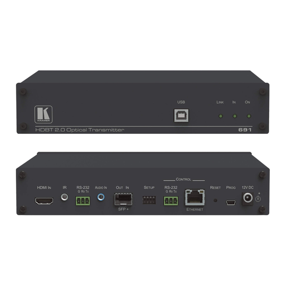
LINK LED Lights green when the HDBT link is valid. IN LED Lights green when an HDMI active signal device is connected. ON LED Lights green when the device receives power. 691 - Defining the 691 HDBT 2.0 Optical Transmitter... -
Page 13: Figure 2: 691 Rear Panel
Figure 2 defines the rear panel of the 691. Figure 2: 691 Rear Panel Feature Function HDMI IN Connector Connect to an HDMI source. IR 3.5mm Mini Jack Connect to an external infrared transmitter or sensor Connector for traffic extension. -
Page 14: Connecting The 691 Hdbt 2.0 Optical Transmitter
3. Connect a stereo analog audio source (for example, the audio output of a PC) to the AUDIO IN 3.5mm mini jack for traffic extension. 4. Connect the USB port on a PC to the USB port on the front panel of the 691 for traffic extension. -
Page 15: Figure 3: Connecting The Fiber Optic Cable
10. Connect the RS-232 3-pin terminal block to the device to be controlled (for example, the projector that is controlled by a serial controller which is connected to 691). 11. Connect the AUDIO OUT 3.5mm mini jack to an audio acceptor, (for example, amplified speakers). Connecting the 691 HDBT 2.0 Optical Transmitter... - Page 16 15. Remove the protective cap and keep for future use. 16. Connect the OUT IN SFP+ LC(UPC) connector to the IN/OUT LC(UPC) connector of the fiber optic cable extension towards the 691 transmitter. Always cross-connect the fiber connections, Rx OUT to Tx IN and Rx IN...
-
Page 17: Figure 4: Connecting The 691 And 692
Figure 4: Connecting the 691 and 692 Connecting the 691 HDBT 2.0 Optical Transmitter... -
Page 18: Using The Osp Sfp+ Module
Using the OSP SFP+ Module Before connecting the 691 to an optical receiver, you need to insert the same type of SFP+ transceiver both into the SFP+ opening on the 691 and the compatible receiver. Two types of Kramer SFP+ optical transceiver modules are available: ... -
Page 19: Figure 5: System Layout Example For Optical Reach Evaluation
In the optical system layout example, illustrated in Figure 691 and 692 are connected to a patch panel via 100m patch cords. There are 6 connectors and no splices. Figure 5: System Layout Example for Optical Reach Evaluation... -
Page 20: Figure 6: Inserting The Transceiver Module
1. Make sure the bail is pushed up, in the closed position. 2. Insert the OSP-MM1/OSP-SM10 into the IN OUT SFP+ slot and push it in until it clicks. Figure 6: Inserting the Transceiver Module 691 - Connecting the 691 HDBT 2.0 Optical Transmitter... -
Page 21: Connecting To 691 Via Rs-232
RS-232 to pass data to and from the machines that are connected to the receiver. RS-232 CONTROL to control the 691. Connect the RS-232 terminal block on the rear panel of the 691 to a PC/controller, as follows (see Figure ... -
Page 22: Connecting 691 Via The Ethernet Port
5.3.1 Connecting the Ethernet Port Directly to a PC You can connect the Ethernet port of the 691 directly to the Ethernet port on your PC using a crossover cable with RJ-45 connectors. This type of connection is recommended for identifying the 691 with the factory configured default IP address. -
Page 23: Figure 8: Local Area Connection Properties Window
4. Highlight either Internet Protocol Version 6 (TCP/IPv6) or Internet Protocol Version 4 (TCP/IPv4) depending on the requirements of your IT system. 5. Click Properties. The Internet Protocol Properties window relevant to your IT system appears as shown in Figure 9 Figure Connecting the 691 HDBT 2.0 Optical Transmitter... -
Page 24: Figure 9: Internet Protocol Version 4 Properties Window
6. Select Use the following IP Address for static IP addressing and fill in the details as shown in Figure For TCP/IPv4 you can use any IP address in the range 192.168.1.1 to 192.168.1.255 (excluding 192.168.1.39) that is provided by your IT department. 691 - Connecting the 691 HDBT 2.0 Optical Transmitter... -
Page 25: Figure 11: Internet Protocol Properties Window
5.3.1.1 Connecting the ETHERNET Port via a Network Hub or Switch You can connect the Ethernet port of the 691 to the Ethernet port on a network hub or network router, via a straight-through cable with RJ-45 connectors. Connecting the 691 HDBT 2.0 Optical Transmitter... -
Page 26: Principles Of Operation
The device can automatically turn off the video signal output and audio source switching after definable intervals following the loss of the input signals or unplugging of the input cables. These delays can be set using the 691 embedded web-pages settings (see Section 8.2) or Protocol 3000 commands (see... -
Page 27: Figure 12: Controlling A Blu-Ray Disk Player Via The 692 Receiver
692 receiver. The IR sensor cable is connected to the 692 and an IR emitter cable is connected between the 691 and the Blu-ray disk player. The Blu-ray disk player remote control sends an IR command while pointed at the external IR sensor. -
Page 28: Figure 13: Controlling A Projector Via The 691 Transmitter
692 using an IR remote control, via the 691. The IR sensor cable is connected to the 691 and the IR emitter cable is connected between the 692 and the projector. -
Page 29: Configuring The 691 Hdbt 2.0 Optical Transmitter
Configuring the 691 HDBT 2.0 Optical Transmitter The 4-way SETUP DIP-switch on the rear panel is used to configure the 691 according to the table below. Figure 14: 691 DIP-Switch Note that all the DIP-switches are set to off (up) by default. -
Page 30: Using The Embedded Web Pages
Using the Embedded Web Pages The 691 can be managed remotely using its embedded Web pages. The Web pages are accessed using a web browser and an Ethernet connection. Before attempting to connect: Connect the 691 via the Ethernet port. -
Page 31: Figure 15: Entering Logon Credentials
You can also use the host name (Unit Name in Device Settings page): 691-xxxx, where xxxx are the last four digits of the serial number of the device. 3. Enter the user name (Admin, Admin, by default). -
Page 32: Setting The Sleep Mode, Hdcp Mode And Audio Switching Delay Time
HDCP mode and the audio switching delay time. To set the sleep mode: 1. In the Navigation pane, click Video & Audio Settings. The Video & Audio Settings page appears (see Figure 16). 691 - Using the Embedded Web Pages... - Page 33 2. Set the video delay time in seconds. 3. Click Set. The delay time is detected by the receiver. For example, the receiver only senses that the clock was lost and acts according to the input signal loss timeout. To set the HDCP mode: 1.
-
Page 34: Setting Device Parameters
Performing a factory reset. To set the device name: 1. In the Navigation pane, click Device Settings. The Device Settings page appears: 2. Type the name in the Name text box and click Set. 691 - Using the Embedded Web Pages... -
Page 35: Figure 17: The Device Settings Page
To change the Ethernet settings manually: 1. In the Navigation pane, click Device Settings. The Device Settings page appears: Figure 17: The Device Settings Page 2. Set DHCP to OFF The DHCP OFF dialog box is displayed. Figure 18: Turning DHCP Off Dialog Box 3. -
Page 36: Figure 19: Turning Dhcp On Warning
Figure 19: Turning DHCP On Warning 4. Click OK. DHCP is turned on. The next time 691 is booted you must reload the Web pages using the IP address issued to the 691 by the DHCP server. To turn DHCP off: 1. - Page 37 To set the UDP/TCP ports: 1. In the Navigation pane, click Device Settings. The Device Settings page appears (see Figure 17). 2. Set the port number. 3. Click Set. To save the current configuration to your PC: 1. In the Navigation pane, click Device Settings. The Device Settings page appears (see Figure 17).
-
Page 38: Managing The Edid
Unit Name. UDP port settings TCP port settings To reset 691 to its factory default values: 1. In the Navigation pane, click Device Settings. The Device Settings page appears (see Figure 17). 2. Click Factory reset. The confirmation message is displayed. -
Page 39: Figure 20: The Edid Management Page
1. In the Navigation pane, click EDID Management. The EDID Management page appears: Figure 20: The EDID Management Page 2. Select one of the following EDID sources: the output, the 691 default, or click Choose a file. 3. Click Copy and wait for the device to complete the process. -
Page 40: Authentication Page
Change. If the Authentication page is left open for more than five minutes additional windows may open. After entering your logon credentials, close the other windows. 691 - Using the Embedded Web Pages... -
Page 41: Viewing The About Page
Viewing the About Page About page lets you view the Web page version and Kramer Electronics Ltd details. Figure 23: The About Page Using the Embedded Web Pages... -
Page 42: Firmware Upgrade
Firmware Upgrade You can upgrade the 691 via the Kramer K-UPLOAD tool. The latest firmware version and the latest version of K-UPLOAD and installation instructions can be downloaded from Kramer Web site at www.kramerav.com/downloads/691. 691 - Firmware Upgrade... -
Page 43: Technical Specifications
Technical Specifications Inputs 1 HDMI On a female HDMI connector 2Vrms / 10kΩ on a 3.5mm mini 1 Stereo Analog Unbalanced Audio jack Outputs 1 Fiber Optic On 2 LC connectors Ports 1 IR On a 3.5mm mini jack for IR link extension 1 USB On a female USB-B connector for... - Page 44 1.45 kg (3.2lbs) approx. Accessories Included Power supply Optional For optimum range and performance use the recommended USB, Ethernet, serial and IR Kramer cables available at www.kramerav.com/product/691 Specifications are subject to change without notice at www.kramerav.com 691 - Technical Specifications...
-
Page 45: Default Communication Parameters
HDCP Follow output Web Logon credentials Name: Admin; Password: Admin 10.3 Default EDID Monitor Model name....691 Manufacturer..... KMR Plug and Play ID..KMR1200 Serial number.... n/a Manufacture date..2015, ISO week 255 Filter driver.... None ------------------------- EDID revision.... 1.3 Input signal type.. - Page 46 2-channel, 16/20/24 bit depths at 32/44/48 kHz CE video identifiers (VICs) - timing/formats supported 1920 x 1080p at 60Hz - HDTV (16:9, 1:1) 1920 x 1080i at 60Hz - HDTV (16:9, 1:1) 1280 x 720p at 60Hz - HDTV (16:9, 1:1) [Native] 691 - Technical Specifications...
- Page 47 720 x 480p at 60Hz - EDTV (16:9, 32:27) 720 x 480p at 60Hz - EDTV (4:3, 8:9) 720 x 480i at 60Hz - Doublescan (16:9, 32:27) 720 x 576i at 50Hz - Doublescan (16:9, 64:45) 640 x 480p at 60Hz - Default (4:3, 1:1) NB: NTSC refresh rate = (Hz*1000)/1001 CE vendor specific data (VSDB) IEEE registration number.
-
Page 48: Protocol 3000
The 691 HDBT 2.0 Optical Transmitter can be operated using the Kramer Protocol 3000 serial commands. The command framing varies according to how you interface with the 691. For example, a basic video input switching command that routes a layer 1 video signal to HDMI out 1 from HDMI input 2 (ROUTE 1,1,2), is entered as follows: ... -
Page 49: Understanding Protocol 3000
You can enter commands directly using terminal communication software (e.g., Hercules) by connecting a PC to the serial or Ethernet port on the 691. To enter CR press the Enter key (LF is also sent but is ignored by the command parser). - Page 50 Spaces between parameters or command terms are ignored. Commands in the string do not execute until the closing character is entered. A separate response is sent for every command in the chain. 691 - Protocol 3000...
-
Page 51: Kramer Protocol 3000 Syntax
11.2 Kramer Protocol 3000 Syntax The Kramer Protocol 3000 syntax uses the following delimiters: CR = Carriage return (ASCII 13 = 0x0D) LF = Line feed (ASCII 10 = 0x0A) SP = Space (ASCII 32 = 0x20) Some commands have short name syntax in addition to long name syntax to enable faster typing. -
Page 52: Protocol 3000 Commands
Get HDCP signal status (system) NAME Set/get machine (DNS) name (system – Ethernet) NAME-RST Reset machine (DNS) name to factory default (system – Ethernet) PRIORITY Get priority for all channels (system) SIGNAL Get input signal lock status (system) 691 - Protocol 3000... - Page 53 11.3.1.1 Functions Permission Transparency Set: End User Public Get: Description Syntax Set: Protocol handshaking Get: Response ~nn@ CR LF Notes Validates the Protocol 3000 connection and gets the machine number Step-in master products use this command to identify the availability of a device K-Config Example “#”,0x0D 11.3.1.2...
- Page 54 1. Multi-line: ~nn@Device available protocol 3000 commands:CR LFcommand,SP command...CR LF 2. Multi-line: ~nn@HELPSPcommand:CR LFdescriptionCR LFUSAGE:usageCR LF Parameters COMMAND_NAME – name of a specific command Notes To get help for a specific command use: HELPSPCOMMAND_NAMECR LF K-Config Example “#HELP”,0x0D 691 - Protocol 3000...
- Page 55 11.3.1.5 MODEL Functions Permission Transparency Set: MODEL? Get: End User Public Description Syntax Set: #MODEL?CR Get: Get device model Response ~nn@MODELSPmodel_nameCR LF Parameters model_name – String of up to 19 printable ASCII chars Notes This command identifies equipment connected to Step-in master products and notifies of identity changes to the connected equipment.
- Page 56 #SN?CR Get: Get device serial number Response ~nn@SNSPserial_numberCR LF Parameters serial_number – 11 decimal digits, factory assigned Notes This device has a 14 digit serial number, only the last 11 digits are displayed K-Config Example “#SN?”,0x0D 691 - Protocol 3000...
- Page 57 11.3.1.9 VERSION Functions Permission Transparency Set: VERSION? Get: End User Public Description Syntax Set: #VERSION?CR Get: Get firmware version number Response ~nn@VERSIONSPfirmware_versionCR LF Parameters firmware_version – XX.XX.XXXX where the digit groups are: major.minor.build version K-Config Example “#VERSION?”,0x0D 11.3.1.10 AV-SW-MODE Functions Permission Transparency Set:...
- Page 58 After every change in output HPD status from Off to On (1) After every change in output HPD status form Off to On and all parameters (new EDID, etc.) are stable and valid (2) K-Config Example Get the output HPD status of HDMI Out: “#DISPLAY? 1”,0x0D 691 - Protocol 3000...
- Page 59 11.3.1.13 HDCP-MOD Functions Permission Transparency HDCP-MOD Set: Administrator Public HDCP-MOD? Get: End User Public Description Syntax #HDCP-MODSPinp_id,modeCR Set: Set HDCP mode #HDCP-MOD?SPinp_idCR Get: Get HDCP mode Response Set / Get: ~ nn @HDCP-MODSPinp_id,modeCR LF Parameters inp_id – input number: 1 (HDMI In) mode –...
- Page 60 The machine name is not the same as the model name. The machine name is used to identify a specific machine or a network in use (with DNS feature on). K-Config Example Set the DNS name of the device to “room-442”: “#NAME room-442”,0x0D 691 - Protocol 3000...
- Page 61 11.3.1.16 NAME-RST Functions Permission Transparency NAME-RST Set: Administrator Public Get: Description Syntax Reset machine (DNS) name to #NAME-RSTCR Set: factory default Get: Response ~nn@NAME-RSTSPOKCR LF Notes Factory default of machine (DNS) name is “KRAMER_” K-Config Example Reset the DNS name of the device to the factory default: “#NAME-RST”,0x0D 11.3.1.17 PRIORITY Functions...
- Page 62 After execution, a response is sent to the com port from which the Get was received A response is sent after every change in input signal status from On to Off or from Off to On K-Config Example Get the input signal lock status of HDMI In: “#SIGNAL? 1”,0x0D 691 - Protocol 3000...
- Page 63 11.3.2 Authentication Commands Command Description LOGIN Set/get protocol permission LOGOUT Cancel current permission level PASS Set/get password for login level SECUR Set/get current security state 11.3.2.1 LOGIN Functions Permission Transparency LOGIN Set: Not Secure Public LOGIN? Get: Not Secure Public Description Syntax #LOGINSPlogin_level,passwordCR...
- Page 64 – level of login to set: User, Admin password – password for the login_level. Up to 15 printable ASCII chars. Notes The default password is an empty string K-Config Example Set the password for the Admin protocol permission level to 33333: “#PASS Admin,33333”,0x0D 691 - Protocol 3000...
- Page 65 11.3.2.4 SECUR Functions Permission Transparency SECUR Set: Administrator Public SECUR? Get: Not Secure Public Description Syntax #SECURSPsecurity_modeCR Set: Start/stop security #SECUR?CR Get: Get current security state Response ~nn@SECURSPsecurity_modeCR LF Parameters security_mode – 1 (On / enable security), 0 (Off / disable security) Notes The permission system works only if security is enabled with the SECUR command K-Config Example...
- Page 66 After execution, a response is sent to the com port from which the get command was received A response is sent to all com ports if the audio status was changed on any input K-Config Example “#AUD-SIGNAL? 1”,0x0D 691 - Protocol 3000...
-
Page 67: Communication Commands
11.3.4 Communication Commands Command Description ETH-PORT Set/get Ethernet port protocol NET-DHCP Set/get DHCP mode NET-GATE Set/get gateway IP NET-IP Set/get IP address NET-MAC Get MAC address NET-MASK Set/get subnet mask 11.3.4.1 ETH-PORT Functions Permission Transparency ETH-PORT Set: Administrator Public ETH-PORT? Get: End User Public... - Page 68 A network gateway connects the device via another network, possibly over the Internet. Be careful of security problems. Consult your network administrator for correct settings. K-Config Example Set the gateway IP address to 192.168.0.1: “#NET-GATE 192.168.000.001”,0x0D 691 - Protocol 3000...
- Page 69 11.3.4.4 NET-IP Functions Permission Transparency NET-IP Set: Administrator Public NET-IP? Get: End User Public Description Syntax #NET-IPSPip_addressCR Set: Set IP address #NET-IP?CR Get: Get IP address Response ~nn@NET-IPSPip_addressCR LF Parameters ip_address – IP address, in the following format: xxx.xxx.xxx.xxx Notes Consult your network administrator for correct settings K-Config Example Set the IP address to 192.168.1.39:...
- Page 70 ~nn@NET-MASKSPnet_maskCR LF Parameters net_mask – format: xxx.xxx.xxx.xxx Response Triggers The subnet mask limits the Ethernet connection within the local network Consult your network administrator for correct settings K-Config Example Set the subnet mask to 255.255.0.0: “#NET-MASK 255.255.000.000”,0x0D 691 - Protocol 3000...
- Page 71 11.3.5 EDID Handling Commands Additional EDID data functions can be performed via the 691 web pages or a compatible EDID management application, such as Kramer EDID Designer (see www.kramerav.com/product/EDID%20Designer). Command Description CPEDID Copy EDID data from the output to the input EEPROM...
- Page 72 – file size in bytes. A file can take more space on device memory file_id – internal ID for file in file system free_size – free space in bytes in device file system K-Config Example “#DIR”,0x0D 691 - Protocol 3000...
- Page 73 11.3.6.2 FS-FREE Functions Permission Transparency Set: FS-free? Get: Administrator Public Description Syntax Set: #FS-FREE?CR Get: Get file system free space Response Multi Line: ~nn@FS_FREESPfree_sizeCR LF Parameters free_size – free size in device file system in bytes K-Config Example “#FS-FREE?”,0x0D 11.3.6.3 Functions Permission Transparency...
- Page 75 SAFETY WARNING Disconnect the unit from the power supply before opening and servicing For the latest information on our products and a list of Kramer distributors, visit our Web site where updates to this user manual may be found. We welcome your questions, comments, and feedback.
Need help?
Do you have a question about the 691 and is the answer not in the manual?
Questions and answers