
Related Manuals for Kramer 610R


Summary of Contents for Kramer 610R
- Page 1 Kramer Electronics, Ltd. USER MANUAL Models: 610T, Detachable Optical DVI Transmitter 610R, Detachable Optical DVI Receiver...
-
Page 2: Table Of Contents
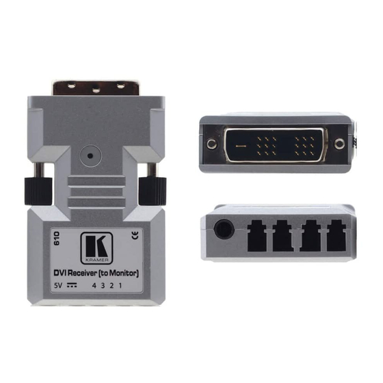
Figure 1: 610 Detachable Optical DVI Transmitter and Receiver Figure 2: The Auto EDID Button on the 610T Figure 3: Connecting the Fiber Optic Cables Figure 4: Connecting the 610T/610R Detachable Optical DVI Transmitter/Receiver Tables Table 1: Technical Specifications of the 610T/610R... -
Page 3: Introduction
Scan Converters and Scalers; GROUP 8: Cables and Connectors; GROUP 9: Room Connectivity; GROUP 10: Accessories and Rack Adapters; GROUP 11: Sierra Products 2 Download up-to-date Kramer user manuals from the Internet at http://www.kramerelectronics.com 3 The complete list of Kramer cables is on our Web site at http://www.kramerelectronics.com... -
Page 4: Overview
1640 ft. (500 meters) of single link high-resolution digital graphic data over four fiber optic cables with LC connectors. The 610T converts electrical signals to optical signals and the 610R decodes the optical signals back to electrical signals. The transmitter can read the display device’s EDID , and... -
Page 5: Powering The 610T And The 610R
3.1 Powering the 610T and the 610R The Kramer 610T can be powered either by an external power adapter or internally by the 5V pin on the DVI card of the computer. The 610T automatically detects if it is being powered via the external power adapter, and if so, the internal power supply will be cut off. -
Page 6: Your Detachable Optical Dvi Transmitter/ Receiver
• Connect the detachable optical DVI transmitter and receiver T he Display Device EDID The 610T and 610R are connected via four channels that transmit R, G, B and clock signals. The EDID of the display device is captured onto the transmitter for the computer to read. -
Page 7: Defining Edid
Using the Detachable Optical DVI System 5.1.1 Defining EDID The Extended Display Identification Data (EDID ) is a data-structure, provided by a display, to describe its capabilities to the DVI graphics source (for example, the graphics card of the computer). The EDID enables the computer to “know”... -
Page 8: Connecting The Detachable Optical Dvi Transmitter/Receiver
2. Plug the 610T DVI connector directly to the DVI connector of the computer. 3. Connect the 610R to the 5V DC power adapter and connect the adapter to the mains electricity. The Indication LED is on. 4. Connect the 610R DVI connector directly to the DVI connector of the display device. -
Page 9: Avoiding Pitfalls Using The 610T And 610R
Display Host Computer Figure 4: Connecting the 610T/610R Detachable Optical DVI Transmitter/Receiver 5.3 Avoiding Pitfalls using the 610T and 610R In the event that any of these problems occur, we recommend the following: If the display device shows only a black screen: •... -
Page 10: Technical Specifications
Technical Specifications Table 1 includes the technical specifications: Table 1: Technical Specifications of the 610T/610R INPUTS: DVI IN (610T), 4 LC optical connectors (610R) OUTPUTS: 4 LC optical connectors (610T), DVI OUT (610R) RESOLUTION: Up to WUXGA @60Hz (1.65Gbps) POWER SOURCE: 5V DC, <500mA... - Page 11 EXCLUSION OF DAMAGES The liability of Kramer for any effective products is limited to the repair or replacement of the product at our option. Kramer shall not be liable for: 1. Damage to other property caused by defects in this product, damages based upon inconvenience, loss of use of the product, loss of time, commercial loss;...
- Page 12 For the latest information on our products and a list of Kramer distributors, visit our Web site: www.kramerelectronics.com, where updates to this user manual may be found. We welcome your questions, comments and feedback. Safety Warning: Disconnect the unit from the power supply before opening/servicing.
Need help?
Do you have a question about the 610R and is the answer not in the manual?
Questions and answers