
Related Manuals for Kramer 692


Summary of Contents for Kramer 692
- Page 1 USER MANUAL MODEL: HDBT 2.0 Optical Receiver P/N: 2900-300524 Rev 5 www.KramerAV.com...
-
Page 2: Table Of Contents
Achieving the Best Performance Safety Instructions Recycling Kramer Products Overview Defining the 692 HDBT 2.0 Optical Receiver Connecting the 692 HDBT 2.0 Optical Receiver Using the OSP SFP+ Module Connecting to 692 via RS-232 Connecting 692 via the Ethernet Port... - Page 3 Figure 9: Internet Protocol Version 4 Properties Window Figure 10: Internet Protocol Version 6 Properties Window Figure 11: Internet Protocol Properties Window Figure 12: Controlling a Blu-ray Disk Player via the 692 Receiver Figure 13: Controlling a Projector via the 691 Transmitter Figure 14: 692 DIP-switch...
-
Page 4: Introduction
In recent years, we have redesigned and upgraded most of our line, making the best even better! Congratulations on purchasing your Kramer 692 HDBT 2.0 Optical Receiver which is part of the Kramer Audio Distribution System and is ideal for: • Ultra-long signals extension for: ▪... -
Page 5: Getting Started
Achieving the Best Performance To achieve the best performance: • Use only good quality connection cables (we recommend Kramer high- performance, high-resolution cables) to avoid interference, deterioration in signal quality due to poor matching, and elevated noise levels (often associated with low quality cables). -
Page 6: Recycling Kramer Products
Kramer Electronics has made arrangements with the European Advanced Recycling Network (EARN) and will cover any costs of treatment, recycling and recovery of waste Kramer Electronics branded equipment on arrival at the EARN facility. For details of Kramer’s recycling arrangements in your particular country go to our recycling pages at www.kramerav.com/support/recycling/. -
Page 7: Overview
HDBaseT 2.0 fiber optics signal received from an extended line transmitter, such as Kramer 691, back into 4K60Hz (4:2:0) HDMI, USB 2.0, Ethernet, RS-232, IR and stereo audio output signals. extends video signals to up to 33km (20.5 miles) over single-mode fiber at up to 4K@60Hz (4:2:0) resolution. - Page 8 DTS-HD, 2K, 4K, and 3D as specified in HDMI 2.0. EDID and CEC signals are passed through from the source to the display. • I-EDIDPro™ Kramer Intelligent EDID Processing™ – Intelligent EDID handling, processing and pass-through algorithm that ensures Plug and Play operation for HDMI source and display systems.
- Page 9 HDBT output link facilitate easy local troubleshooting. Remote device management via built-in web UI and RS-232 connection enable simple device maintenance. Kramer Network support provides remote device and network management. Local and remote firmware upgrade via mini-USB, RS-232 or Ethernet connection and the K-Upload tool ensure lasting, field- proven deployment.
-
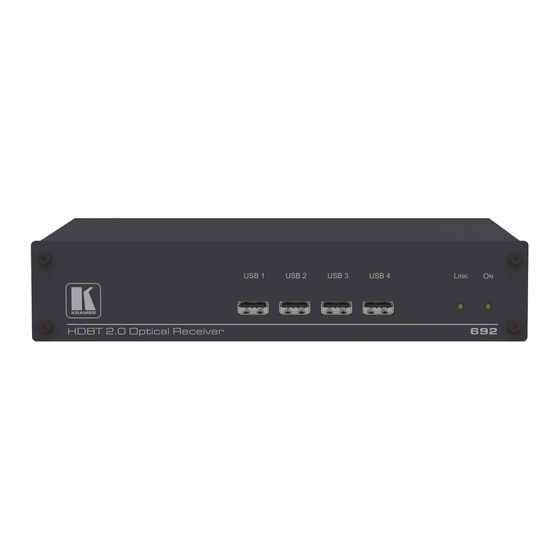
Page 10: Defining The 692 Hdbt 2.0 Optical Receiver
LINK LED Lights green when the HDBT link is valid. IN LED Lights green when an HDMI active signal device is connected. ON LED Lights green when the device receives power. 692 – Defining the 692 HDBT 2.0 Optical Receiver... -
Page 11: Figure 2: 692 Rear Panel
Press and hold for 5 seconds to reset the device to factory default settings. Press and immediately release to power-cycle the device (Reset). PROG Mini USB Connector Use for firmware upgrade. 12V DC Power Connector Connect to the supplied power adapter. 692 - Defining the 692 HDBT 2.0 Optical Receiver... -
Page 12: Connecting The 692 Hdbt 2.0 Optical Receiver
5 Connecting the 692 HDBT 2.0 Optical Receiver Always switch off the power to each device before connecting it to your 692. After connecting your 692, connect the power to and switch on each device. You can use the HDBT 2.0 Optical Receiver and a compatible receiver, for example, the Kramer HDBT 2.0 Optical Transmitter to configure a paired... -
Page 13: Figure 4: Connecting The Fiber Optic Cable
Always cross-connect the fiber connections, Rx OUT to Tx IN and Rx IN to Tx OUT, as transmission is carried on simplex fiber strands. Figure 4: Connecting the Fiber Optic Cable 692 - Connecting the 692 HDBT 2.0 Optical Receiver... - Page 14 7. Connect the supplied power adapter to the power socket and plug the adapter into the mains electricity (not shown in Figure To connect the 692 HDBT 2.0 Optical Receiver: 1. Connect the HDMI OUT connector to an HDMI acceptor, (for example, a projector).
-
Page 15: Using The Osp Sfp+ Module
Figure Using the OSP SFP+ Module By default, OSP-MM1 is inserted in 692. If required, replace the optical transceiver, you need to insert the same type of SFP+ transceiver both into the SFP+ opening on the and the compatible transmitter. - Page 16 • Avoid placing optical devices in the emitted beam that could cause the concentration of the laser radiation to be increased. Connecting the 692 HDBT 2.0 Optical Receiver...
-
Page 17: Figure 5: System Layout Example For Optical Reach Evaluation
Typical loss for each patch cord (100m) is 0.1dB. • Fiber optic loss is 1 dB/km. Single-mode bulk line loss budget is: 11.9 – (0.3x6 +0.1x2) = 9.9dB. Evaluated bulk line length is: 9.9/1=~9.9km. 692 - Connecting the 692 HDBT 2.0 Optical Receiver... -
Page 18: Figure 6: Inserting The Transceiver Module
IN OUT SFP+ slot and push it in until it clicks. Figure 6: Inserting the Transceiver Module 4. Remove the protective cap and keep for future use. For more information, see the OSP-MM1/OSP-SM10 documentation available at www.kramerav.com/product/osp-mm1. Connecting the 692 HDBT 2.0 Optical Receiver... -
Page 19: Connecting To 692 Via Rs-232
Via a network hub, switch, or router, using a straight-through cable (see Section 5.3.1.1). If you want to connect via a router and your IT system is based on IPv6, speak to your IT department for specific installation instructions. 692 - Connecting the 692 HDBT 2.0 Optical Receiver... -
Page 20: Figure 8: Local Area Connection Properties Window
3. Highlight the network adapter you want to use to connect to the device and click Change settings of this connection. The Local Area Connection Properties window for the selected network adapter appears as shown in Figure Figure 8: Local Area Connection Properties Window Connecting the 692 HDBT 2.0 Optical Receiver... -
Page 21: Figure 9: Internet Protocol Version 4 Properties Window
The Internet Protocol Properties window relevant to your IT system appears as shown in Figure 9 Figure Figure 9: Internet Protocol Version 4 Properties Window Figure 10: Internet Protocol Version 6 Properties Window 692 - Connecting the 692 HDBT 2.0 Optical Receiver... -
Page 22: Figure 11: Internet Protocol Properties Window
Connecting the ETHERNET Port via a Network Hub or Switch You can connect the Ethernet port of the to the Ethernet port on a network hub or network router, via a straight-through cable with RJ-45 connectors. Connecting the 692 HDBT 2.0 Optical Receiver... -
Page 23: Principles Of Operation
Since the IR connection between the transmitter and receiver is bidirectional, you can use a remote control transmitter (that is used for controlling a peripheral device, for example, a Blu-ray disk player) to send commands from 692 - Principles of Operation... -
Page 24: Figure 12: Controlling A Blu-Ray Disk Player Via The 692 Receiver
To use a remote control transmitter, connect the Kramer IR sensor cable at one end and the Kramer IR emitter cable at the other end. Two sample cases are presented below. The example in... -
Page 25: Figure 13: Controlling A Projector Via The 691 Transmitter
IR sensor. The IR signal is passed over the fiber optic link and the IR emitter cable to the projector which responds to the command sent. Figure 13: Controlling a Projector via the 691 Transmitter 692 - Principles of Operation... -
Page 26: Configuring The 692 Hdbt 2.0 Optical Receiver
7 Configuring the 692 HDBT 2.0 Optical Receiver Figure 14: 692 DIP-switch Note that all the DIP-switches are set to off (up) by default. Function Status For future use. For future use. Off (up) – Automatic EDID acquisition (factory EDID lock default). -
Page 27: Using The Embedded Web Pages
• Authentication (see Section 8.5). • Viewing the Web version and other Kramer details (see Section 8.6). Browsing the 692 Web Pages In the event that a Web page does not update correctly, clear your web browser’s cache by pressing CTRL+F5. -
Page 28: Figure 15: Entering Logon Credentials
You can also use the host name (Unit Name in Device Settings page): 692-xxxx, where xxxx are the last four digits of the serial number of the device. 3. Enter the user name (Admin, Admin, by default). -
Page 29: Setting The Sleep Mode And Hdcp Mode
2. Set the video delay time in seconds. 3. Click Set. The delay time is detected by the receiver. For example, the receiver only senses that the clock was lost and acts according to the input signal loss timeout. 692 - Using the Embedded Web Pages... -
Page 30: Setting Device Parameters
To set the HDCP mode: 1. In the Navigation pane, click Video Settings. The Video Settings page appears (see Figure 16). 2. View the HDCP input status. 3. Enable or disable the HDCP mode. You must set the HDCP preferences in at least the transmitter or receiver. -
Page 31: Figure 17: The Device Settings Page
1. In the Navigation pane, click Device Settings. The Device Settings page appears: Figure 17: The Device Settings Page 2. Set DHCP to OFF The DHCP OFF dialog box is displayed. Figure 18: Turning DHCP Off Dialog Box 692 - Using the Embedded Web Pages... -
Page 32: Figure 19: Turning Dhcp On Warning
3. Change any of the parameters (IP Address, Mask and/or Gateway address). 4. Click Set. To automatically set Ethernet settings: 1. In the Navigation pane, click Device Settings. The Device Settings page appears (see Figure 17): 2. Set DHCP to ON. 3. - Page 33 2. Open the embedded Web pages (see Section 8.1). 3. In the Navigation pane, click Device Settings. The Device Settings page appears (see Figure 17). 4. Click Load. The explorer window opens. 5. Browse to the required file. 692 - Using the Embedded Web Pages...
-
Page 34: Managing The Edid
▪ Unit Name. ▪ UDP port settings ▪ TCP port settings To reset 692 to its factory default values: 1. In the Navigation pane, click Device Settings. The Device Settings page appears (see Figure 17). 2. Click Factory reset. The confirmation message is displayed. -
Page 35: Figure 20: The Edid Management Page
3. Click Copy and wait for the device to complete the process. The “EDID was copied successfully” message is displayed and the EDID data is copied to the input. Figure 21: The EDID Message 4. Click OK. 692 - Using the Embedded Web Pages... -
Page 36: Authentication Page
The Input EDID Summary Information area displays the current selection of EDID source, video resolution, audio availability, and so on. 5. Set DIP-switch 3 to ON (down). The new EDID is saved and locked. Authentication Page The Authentication page lets you assign or change logon authentication details. By-default User and Password are both Admin. -
Page 37: Viewing The About Page
Viewing the About Page About page lets you view the Web page version and Kramer Electronics Ltd details. Figure 23: The About Page 692 - Using the Embedded Web Pages... -
Page 38: Technical Specifications
9 Technical Specifications Inputs 1 Fiber Optic On 2 LC connectors Outputs 1 HDMI On a female HDMI connector 2Vrms / 10kΩ on a 3.5mm mini 1 Stereo Analog Unbalanced Audio jack Ports 1 IR On a 3.5mm mini jack for IR link extension 4 USB On female USB-A connectors... - Page 39 21.46cm x 16.3 cm x 4.36cm (8.45" x 6.42" x 1.7") Shipping Dimensions (W, D, H) 35.1cm x 21.2cm x 7.2cm (13.82" x 8.35" x 2.8") Net Weight 0.95 kg (2.1lbs) Shipping Weight 1.45 kg (3.2lbs) approx. 692 - Technical Specifications...
-
Page 40: Default Communication Parameters
Power adapter (12V, 5A), OSP-MM1 optical transceiver For optimum range and Optional performance use the recommended USB, Ethernet, serial and IR Kramer cables available at www.kramerav.com/product /692 www.kramerav.com Specifications are subject to change without notice at Default Communication Parameters RS-232... -
Page 41: Default Edid
800 x 600p at 85Hz - VESA STD 640 x 480p at 85Hz - VESA STD 1152 x 864p at 70Hz - VESA STD 1280 x 960p at 60Hz - VESA STD EIA/CEA-861 Information Revision number..3 IT underscan..... Supported Basic audio....Supported 692 - Technical Specifications... - Page 42 YCbCr 4:4:4....Supported YCbCr 4:2:2....Supported Native formats... 1 Detailed timing #1..1920x1080p at 60Hz (16:10) Modeline...."1920x1080" 148.500 1920 2008 2052 2200 1080 1084 1089 1125 +hsync +vsync Detailed timing #2..1920x1080i at 60Hz (16:10) Modeline...."1920x1080" 74.250 1920 2008 2052 2200 1080 1084 1094 1124 interlace +hsync +vsync Detailed timing #3..
-
Page 43: Protocol 3000
HDBT 2.0 Optical Receiver can be operated using the Kramer Protocol 3000 serial commands. The command framing varies according to how you interface with the 692. For example, a basic video input switching command that routes a layer 1 video signal to HDMI out 1 from HDMI input 2 (ROUTE 1,1,2), is entered as follows: •... -
Page 44: Understanding Protocol 3000
You can enter commands directly using terminal communication software (e.g., Hercules) by connecting a PC to the serial or Ethernet port on the 692. To enter CR press the Enter key (LF is also sent but is ignored by the command parser). -
Page 45: Kramer Protocol 3000 Syntax
Commands in the string do not execute until the closing character is entered. A separate response is sent for every command in the chain. 10.2 Kramer Protocol 3000 Syntax The Kramer Protocol 3000 syntax uses the following delimiters: • CR = Carriage return (ASCII 13 = 0x0D) •... - Page 46 The Protocol 3000 syntax is in the following format: • Host Message Format: Start Address (optional) Body Delimiter Device_id@ Message • Simple Command – Command string with only one command without addressing: Start Body Delimiter Command SP Parameter_1,Parameter_2,… • Command String – Formal syntax with command concatenation and addressing: Start Address...
-
Page 47: Protocol 3000 Commands
Set/get HDCP mode (system) HDCP-STAT Get HDCP signal status (system) NAME Set/get machine (DNS) name (system – Ethernet) NAME-RST Reset machine (DNS) name to factory default (system – Ethernet) SIGNAL Get input signal lock status (system) 692 - Protocol 3000... - Page 48 10.3.1.1 Functions Permission Transparency Set: End User Public Get: Description Syntax Set: Protocol handshaking Get: Response ~nn@ CR LF Notes Validates the Protocol 3000 connection and gets the machine number Step-in master products use this command to identify the availability of a device K-Config Example “#”,0x0D 10.3.1.2...
- Page 49 1. Multi-line: ~nn@Device available protocol 3000 commands:CR LFcommand,SP command...CR LF 2. Multi-line: ~nn@HELPSPcommand:CR LFdescriptionCR LFUSAGE:usageCR LF Parameters COMMAND_NAME – name of a specific command Notes To get help for a specific command use: HELPSPCOMMAND_NAMECR LF K-Config Example “#HELP”,0x0D 692 - Protocol 3000...
- Page 50 10.3.1.5 MODEL Functions Permission Transparency Set: MODEL? Get: End User Public Description Syntax Set: #MODEL?CR Get: Get device model Response ~nn@MODELSPmodel_nameCR LF Parameters model_name – String of up to 19 printable ASCII chars Notes This command identifies equipment connected to Step-in master products and notifies of identity changes to the connected equipment.
- Page 51 #SN?CR Get: Get device serial number Response ~nn@SNSPserial_numberCR LF Parameters serial_number – 11 decimal digits, factory assigned Notes This device has a 14 digit serial number, only the last 11 digits are displayed K-Config Example “#SN?”,0x0D 692 - Protocol 3000...
- Page 52 10.3.1.9 VERSION Functions Permission Transparency Set: VERSION? Get: End User Public Description Syntax Set: #VERSION?CR Get: Get firmware version number Response ~nn@VERSIONSPfirmware_versionCR LF Parameters firmware_version – XX.XX.XXXX where the digit groups are: major.minor.build version K-Config Example “#VERSION?”,0x0D 10.3.1.10 AV-SW-TIMEOUT Functions Permission Transparency AV-SW-TIMEOUT...
- Page 53 After every change in output HPD status from Off to On (1) After every change in output HPD status form Off to On and all parameters (new EDID, etc.) are stable and valid (2) K-Config Example Get the output HPD status of HDMI Out: “#DISPLAY? 1”,0x0D 692 - Protocol 3000...
- Page 54 10.3.1.12 HDCP-MOD Functions Permission Transparency HDCP-MOD Set: Administrator Public HDCP-MOD? Get: End User Public Description Syntax #HDCP-MODSPinp_id,modeCR Set: Set HDCP mode #HDCP-MOD?SPinp_idCR Get: Get HDCP mode Response Set / Get: ~nn@HDCP-MODSPinp_id,modeCR LF Parameters inp_id – input number: 1 (HDMI In) mode –...
- Page 55 The machine name is not the same as the model name. The machine name is used to identify a specific machine or a network in use (with DNS feature on). K-Config Example Set the DNS name of the device to “room-442”: “#NAME room-442”,0x0D 692 - Protocol 3000...
- Page 56 10.3.1.15 NAME-RST Functions Permission Transparency NAME-RST Set: Administrator Public Get: Description Syntax Reset machine (DNS) name to #NAME-RSTCR Set: factory default Get: Response ~nn@NAME-RSTSPOKCR LF Notes Factory default of machine (DNS) name is “KRAMER_” K-Config Example Reset the DNS name of the device to the factory default: “#NAME-RST”,0x0D 10.3.1.16 SIGNAL Functions...
- Page 57 The permission system works only if security is enabled with the SECUR command. It is not mandatory to enable the permission system in order to use the device K-Config Example Set the protocol permission level to Admin (when the password defined in the PASS command is 33333): “#LOGIN Admin,33333”,0x0D 692 - Protocol 3000...
- Page 58 10.3.2.2 LOGOUT Functions Permission Transparency LOGOUT Set: Not Secure Public Get: Description Syntax #LOGOUTCR Set: Cancel current permission level Get: Response ~nn@LOGOUTSPOKCR LF Notes Logs out from User or Administrator permission levels K-Config Example “#LOGOUT”,0x0D 10.3.2.3 PASS Functions Permission Transparency PASS Set: Administrator...
- Page 59 ~nn@SECURSPsecurity_mode CR LF Parameters security_mode – 1 (On / enable security), 0 (Off / disable security) Notes The permission system works only if security is enabled with the SECUR command K-Config Example Enable the permission system: “#SECUR 1”,0x0D 692 - Protocol 3000...
- Page 60 10.3.3 Communication Commands Command Description ETH-PORT Set/get Ethernet port protocol NET-DHCP Set/get DHCP mode NET-GATE Set/get gateway IP NET-IP Set/get IP address NET-MAC Get MAC address NET-MASK Set/get subnet mask 10.3.3.1 ETH-PORT Functions Permission Transparency ETH-PORT Set: Administrator Public ETH-PORT? Get: End User Public...
- Page 61 A network gateway connects the device via another network, possibly over the Internet. Be careful of security problems. Consult your network administrator for correct settings. K-Config Example Set the gateway IP address to 192.168.0.1: “#NET-GATE 192.168.000.001”,0x0D 692 - Protocol 3000...
- Page 62 10.3.3.4 NET-IP Functions Permission Transparency NET-IP Set: Administrator Public NET-IP? Get: End User Public Description Syntax #NET-IPSPip_addressCR Set: Set IP address #NET-IP?CR Get: Get IP address Response ~nn@NET-IPSPip_addressCR LF Parameters ip_address – IP address, in the following format: xxx.xxx.xxx.xxx Notes Consult your network administrator for correct settings K-Config Example Set the IP address to 192.168.1.39:...
- Page 63 ~nn@NET-MASKSPnet_maskCR LF Parameters net_mask – format: xxx.xxx.xxx.xxx Response Triggers The subnet mask limits the Ethernet connection within the local network Consult your network administrator for correct settings K-Config Example Set the subnet mask to 255.255.0.0: “#NET-MASK 255.255.000.000”,0x0D 692 - Protocol 3000...
- Page 64 10.3.4 EDID Handling Commands Additional EDID data functions can be performed via the web pages or a compatible EDID management application, such as Kramer EDID Designer (see www.kramerav.com/product/EDID%20Designer). Command Description CPEDID Copy EDID data from the output to the input EEPROM...
- Page 65 – file size in bytes. A file can take more space on device memory file_id – internal ID for file in file system free_size – free space in bytes in device file system K-Config Example “#DIR”,0x0D 692 - Protocol 3000...
- Page 66 10.3.5.2 FS-FREE? Functions Permission Transparency Set: FS-FREE? Get: Administrator Public Description Syntax Set: #FS-FREE?CR Get: Get file system free space Response Multi Line: ~nn@FS_FREESPfree_sizeCR LF Parameters free_size – free size in device file system in bytes K-Config Example “#FS-FREE?”,0x0D 10.3.5.3 Functions Permission Transparency...
- Page 67 This limited warranty gives you specific legal rights, and you may have other rights which vary from country to country or state to sta te. This limited warranty is void if (i) the label bearing the serial number of this product has been removed or defaced, (ii) the product is not distributed by Kramer Electronics or (iii) this product is not purchased from an authorized Kramer Electronics reseller.
- Page 68 SAFETYWARNING Disconnect the unit from the power supply before opening and servicing For the latest information on our products and a list of Kramer distributors, visit our Web site where updates to this user manual may be found. We welcome your questions, comments, and feedback.
Need help?
Do you have a question about the 692 and is the answer not in the manual?
Questions and answers