Table of Contents
Advertisement
Advertisement
Table of Contents

Summary of Contents for FINE mechatronics FS-8000
- Page 1 FS-8000 Digital Weighing Indicator INSTRUCTION MANUAL...
-
Page 2: Table Of Contents
SERIAL INTERFACE .........37 5-3-1 RS-232C SERIAL INTERFACE....5-3-2 OP-02 CURRENT LOOP......ADDITIONAL SET UP FUNCTION.... 42 5-4-1 OP-03 BCD OUT........5-4-2 OP-04 RS-422/485 SERIAL ....5-4-3 OP-05/06 ANALOG OUT......5-4-4 OP-07 PRINTER........5-4-5 OP-10 BCD INPUT........ --------------------------------------------------------------------------------- FINE MECHATRONICS FS8000... -
Page 3: Chapter 1. Preface
FS-8000 is designed to withstand harsh environmental conditions and is designed for flawless Performance in your demanding application. Also,FS-8000 have several options that is both versatile and easily connectable to other devices. ※ APPLICATION 1. PACKING EQUIPMENTS FOR MANUAL WEIGHING 2. -
Page 4: Features
- Various option Functions for customer`s satisfaction such as RS-422/485, Current Loop, Analog out, BCD Input/Output and so on. - RS-232C Serial Interface & Printer was installed basically Avilable to print by either Serial Interface or Centronics Parallel Interface --------------------------------------------------------------------------------- FINE MECHATRONICS FS8000... -
Page 5: Front Panel Description
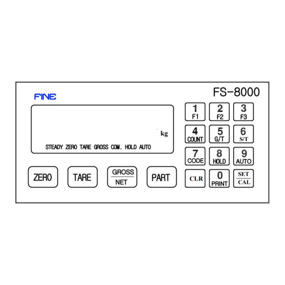
1-4. FRONT PANEL DESCRIPTION FS-8000 COUNT STEADY ZERO TARE GROSS COM. HOLD AUTO CODE HOLD AUTO GROSS ZERO TARE PART PRINT 1-4-1. LAMP ▼ STEADY : This Lamp will be turned on the stable weight The condition of STEADY Lamp can set up by F04,F08. -
Page 6: How To Use Key
: Usable to confirm or change the product part * Can set up the data of each product from 1 No to 20 No. - Checking PART : PART Key → CLR Key - Changing PART : PART Key → Numeral Key →SET key --------------------------------------------------------------------------------- FINE MECHATRONICS FS8000... - Page 7 - Available to work the HOLD function by AUTO setting Only And to remove the HOLD function when it empty. - Auto-totallization when the weight is safty * Possible to choose AUTO/MANUAL by SET UP F19 when the power is ON. --------------------------------------------------------------------------------- FINE MECHATRONICS FS8000...
- Page 8 CLR Key,If no a addtional data,it will be deleted automatically. * After ☞ SET/CAL Key : key have 2way to use as follows 1) When recording each setted data 2) When using SETUP or CALIBRATION( 3Chapter, 4Chapter REFERENCE) --------------------------------------------------------------------------------- FINE MECHATRONICS FS8000...
-
Page 9: Rear-Side Panel
POWER S/W) ON/OFF It will be safe to use it after 10minuate for a precise measurements 5. DATA OUT (OPTION BOARD) : Serial Communication.RS422, BCD OUTPUT, Analog Voltage, Electric Currnet(Analog Out) 0-10V or 4-20mA, Print Out --------------------------------------------------------------------------------- FINE MECHATRONICS FS8000... - Page 10 SIG+ SIG- SHIELD 10. ADJUST : DIP Switch for ZERO and SPAN Control ( 1-6No : ZERO , 7-8No : SPAN , 10No : Calibration Lock Functions of each input terminal is to choose SETUP F16. --------------------------------------------------------------------------------- FINE MECHATRONICS FS8000...
-
Page 11: Specification
: BCD Out OP-04 Serial I/F : RS422, RS485 OP-05 Analog Output : Vout (0-10V / 10V-0V) OP-06 Analog Output : Iout (4-20mA / 20-4mA) OP-07 Print I/F : CENTRONICS Parallel OP-10 Parallel I/F : BCD In PART --------------------------------------------------------------------------------- FINE MECHATRONICS FS8000... -
Page 12: The Example For The Connecting To External Devices
To external devices EXTERAL DISPLAY Centronics PARALLEL Summing PRINTER BCD OUT P.L.C ANALOG OUT 0∼10V Loadcell 4∼20mA Loadcell ANALOG Loadcell RECODER Loadcell ※Printer : FS-7000D,FS-7000P FS-7024, FS-7040P ※External DISPLAY : FS-4200, FS-4400 Serial interface (RS232C,RS422) COMPUTER --------------------------------------------------------------------------------- FINE MECHATRONICS FS8000... -
Page 13: Chapter 2. Installation
: 2EA (PIPE TYPE 250V 0.3A SMALL TYPE) - LOAD CELL CONNECTOR : 1EA (N16-05) - OPERATING MANUAL : 1EA - A Stable Connector for Option installation. LIVE NEUTRAL Chassis Ground ※ The connection of power cable --------------------------------------------------------------------------------- FINE MECHATRONICS FS8000... -
Page 14: Out-Dimmension & Cutting Size
2-1.Out-Dimmension & CUTTING SIZE --------------------------------------------------------------------------------- FINE MECHATRONICS FS8000... -
Page 15: Assemble Drawing
2-2. ASSEMBLE DRAWING --------------------------------------------------------------------------------- FINE MECHATRONICS FS8000... -
Page 16: How To Connect Loadcell
HUNTLEIGH GREEN BLACK WHITE SHIELD ※ Load cell Connector Standard : N16-05 ※ Because Wire color may be different according to a manufacturer and load cell models. Please refer for the data sheet of load cell. --------------------------------------------------------------------------------- FINE MECHATRONICS FS8000... -
Page 17: Error & A/S
Load cell connector Appear "UL" Indicator. (UNDER LOAD) Zero adjustment. ZERO adjustment. ( 5000-15000 ) Load cell demage Load cell demage Connection Error Load cell connector Appear "OL" (OVER LOAD) Excess Max weight Remove excess weight --------------------------------------------------------------------------------- FINE MECHATRONICS FS8000... -
Page 18: Chapter 3.Calibration
Adjust the dip-switch that The number appearing on the display should be closed to 5000. (Example) While pushing key + Power turn on -> tESt While displaying tESt + key,puse key again. Then this value will be zero value. --------------------------------------------------------------------------------- FINE MECHATRONICS FS8000... - Page 19 The changing range of Each dip-switch is as follows Dip-switch Changed range 1960 3920 7840 15680 31360 If 1,2,3,5 dip-switch was OFF,the changed range is 980+1960+3920+15680=22540. As the resulf of,it will come to 27300-22540=4760 and will result in about 5000. --------------------------------------------------------------------------------- FINE MECHATRONICS FS8000...
- Page 20 ---------- Display is "St. CAL" 3. Pushing SET/CAL key ---------- Display is "d 02" ☞ The second way If pushing SET/CAL key for 3sec,it will be displayed "St. CAL" "St. CAL" means SETUP & CALIBRATION mode --------------------------------------------------------------------------------- FINE MECHATRONICS FS8000...
- Page 21 After appearing ,the discretion number(Max.5figure) will appear. SET/CAL key. If the present number is closed by 5,000,please push If a discretion number don`t appear and is over 20000, Please do it as the zero adjustment instruction. --------------------------------------------------------------------------------- FINE MECHATRONICS FS8000...
- Page 22 ☞ 7Step The "END" message is displayed in 6 step, all span adjustment is end. Press SET key after put down of span standard weight on the platform. The indicator will enter into user's weighing mode. --------------------------------------------------------------------------------- FINE MECHATRONICS FS8000...
- Page 23 The weight will be safty SET/CAL Key Pushing SET/CAL key "FInE" Push after checking inside After unloading a balance ZERO & 7 Segment display 7 STEP 0.00 If it display In the weight display It will be normal --------------------------------------------------------------------------------- FINE MECHATRONICS FS8000...
-
Page 24: Error Messages & Adjust
NO 1 ~6 of Dip-Switch is to adjust ZERO. NO 7 ~8 of Dip-Switch is to adjust SPAN Also because ZERO was changed according to NO 7 ~8 of Dip-Switch, 3-1 ZERO Adjustment Please adjust ZERO again as --------------------------------------------------------------------------------- FINE MECHATRONICS FS8000... - Page 25 2times 3times Very Big 4times ※ If it continue to display ERR--06 in spite of adjusting the Dip-Switch as the above, Please check it if the cable wire of a Load cell was normal or nor. --------------------------------------------------------------------------------- FINE MECHATRONICS FS8000...
- Page 26 ①Cause : In case the connection of a Load cell was not normal or a Load cell was broken. ②Adjust : Pleare refer to the part related with a Load cell or Remove a excess weight. --------------------------------------------------------------------------------- FINE MECHATRONICS FS8000...
-
Page 27: Chapter 4. Set-Up
② If you proceed to next function,press CLR key or, If you want to see your desirous any function number, Press "CLR" key after input any function number by numeric key. Indicator will display function number directly from present function number. --------------------------------------------------------------------------------- FINE MECHATRONICS FS8000... -
Page 28: F-Function Summary List
Please press key " 0 " + " CLR " consecutively. ERR--07 ※ ①Cause : In case it was deviated from a range of value which can be set by SET UP, ②Adjust : Please input the contents of SET UP again. --------------------------------------------------------------------------------- FINE MECHATRONICS FS8000... - Page 29 Weight choice for output Display,Gross,Net weight F 51 BCD OUT Parity Positive / Negative OUT F-60 GROUP-SETTING Analog Out Specification F 60 Weight choice for output Display,Gross,Net weight Standard weight choice of Analog Out Max,display weight,Standard weight F 61 --------------------------------------------------------------------------------- FINE MECHATRONICS FS8000...
-
Page 30: Chapter 5. Set-Up Illustration
When the weight change`s difference was in the range set for a time, This function will make it safty. If the factory environment have much vibration,pleae enlarge the motion band. Also,if it was lower,please make it smaller. --------------------------------------------------------------------------------- FINE MECHATRONICS FS8000... - Page 31 * First Setting : 10 ( 1 sec) * 0.1sec Delay/per 1count AVAILABLE ZERO RANGE SETTING Zero value of 1000 ~ 20,000 while working. F09- No availabel to Zero value while working Unavailable to set by F02-01( BACK-UP) --------------------------------------------------------------------------------- FINE MECHATRONICS FS8000...
-
Page 32: Basic Function For Devices
It will be AUTO TARE REMOVING. ( It is comfortable in case that the filling works after loadiing TARE on the weighing part. * In case selecting NO 2,3,The TRAE Key will be worked to NO 1 --------------------------------------------------------------------------------- FINE MECHATRONICS FS8000... - Page 33 * Input in connecting COM terminal and Input Terminal. The time to input is over 0.05 sec * Convert in inputting N/W. Delete Totalization Information CLR + SUB TOTAL , Deleting in inputting F18- CLR + TOTAL Auto deleting in printing Sub-Total,TOTAL --------------------------------------------------------------------------------- FINE MECHATRONICS FS8000...
- Page 34 P.N WORK FINISH TIME. F2 KEY FUNCTION SETTING BY USER. The above F1 FUNCTION SETTING is the same F22- No available F3 KEY FUNCTION SETTING BY USER The above F1 FUNCTION SETTING is the same F23- No available --------------------------------------------------------------------------------- FINE MECHATRONICS FS8000...
- Page 35 When maxium weight was displayed(1 time) Holding a weight when Maxium weight was displayed when Maxium weight was renew. NOMINATION CODE NUMBER FIXING 1 Increase after weighing 1time F26- 1 Decrease after weighing 1time ( "0" is No Decrease) --------------------------------------------------------------------------------- FINE MECHATRONICS FS8000...
- Page 36 → key → key → SET/CAL key → * DATA & TIME was subjected to the OPTION setting. CHECK A/S COUNT OF BASIC ZERO F98- * This key was used to check a load cell Error. --------------------------------------------------------------------------------- FINE MECHATRONICS FS8000...
-
Page 37: Serial Interface
* No availabel in case fo F33 - 02 NSERT TRANSMIT DATA(STX NO STX F34- Transmition of STX(ASCII=02) CONTROL INTERFACE WIRE/ RS422 (485) NO USE for CS, RS / in case of RS422,485 F35- USE FOR CS, RS --------------------------------------------------------------------------------- FINE MECHATRONICS FS8000... -
Page 38: Rs-232C Serial Interface
Start bit Parity bit or MSB 7 STREAM MODE ▩ It is doing Data Output in Stream Mode whenever A/D Converts Refer) A/D Conversion : Appr.25times/sec in lower weight. A/D Conversion : Appr.15times/sec in Heavy Duty weight. --------------------------------------------------------------------------------- FINE MECHATRONICS FS8000... - Page 39 - 2D(H) “ - ” : MINUS - 2O(H) “ ” : SPACE - 2E(H) “ . ” : Decimal Point ▶ Unit - kg : Unit of Kilrogram t : Unit of TON - l b : Unit of Pound --------------------------------------------------------------------------------- FINE MECHATRONICS FS8000...
- Page 40 In case of setting of F30-00, F31-00, F32-00, F33-00, F34-00 Basic Program 10 OPEN "COM1: 300, E, 7, 1, DS, CS" AS # 1 20 INPUT #1, A$, B$, C$ 30 PRINT A$, B$, C$ 40 GOTO 20 --------------------------------------------------------------------------------- FINE MECHATRONICS FS8000...
-
Page 41: Current Loop
* Please use the connector like RS-232C Interface * Transmittion terminal was NO Polarity. * Reception terminal was supplied with 12V for a current supply 1 1 1 1 9 CURRENT 7 GND 11 CURREN 18 CURREN 25 CURREN --------------------------------------------------------------------------------- FINE MECHATRONICS FS8000... - Page 42 If you try to set F90 then A equipement ID NO(“ID(2”) must be added to the head of All command also the head of RESPONSE will be transmitted with ID NO(2Digit) and “ , “ * F34- 01 : The Start of ALL Interface must be done by STX(ASCII=02). --------------------------------------------------------------------------------- FINE MECHATRONICS FS8000...
-
Page 43: Additional Set Up Function
2×10 4×10 8×10 1×10 2×10 4×10 EX. Vcc 8×10 EX. Vcc 1×10 2×10 4×10 Hi : Positive Polarity 8×10 Decimal Point 1×10 " 2×10 " 4×10 8×10 OVER LOAD 1×10 BUSY 2×10 HOLD (INPUT) 4×10 8×10 --------------------------------------------------------------------------------- FINE MECHATRONICS FS8000... - Page 44 ► When inserting a fullup resistance ,please change 5v ∼ 30V in 37,39 NO Resistance and Voltage . 5V = 1 kΩ , 10V = 2 kΩ , 15V = 2.7kΩ , 24V = 5 kΩ --------------------------------------------------------------------------------- FINE MECHATRONICS FS8000...
-
Page 45: Rs-422/485 Serial
↙ ↑ Start 1 bit Parity bit (2) Data Format It`s the Same with RS - 232C (3) RS-422 / 485 Circuit (9P D-Type Female Connector) 1 FG 2 RXD(+) 3 RXD(-) 6 TXD(+) 7 TXD(-) --------------------------------------------------------------------------------- FINE MECHATRONICS FS8000... -
Page 46: Analog Out
Positive out : 4mA, 0V while weight is 0 F62- Negative out : 20mA, 5V, 10V while weight is 0 Analog Out Standard Weight Selecting. Analog max out value when weight setup. F63- * first Setting 000000 --------------------------------------------------------------------------------- FINE MECHATRONICS FS8000... - Page 47 * The voltage out is to 10V when the weight is displayed max.capacity in indicator. * If analog output is not correct, You can make a fine adjustment with VR1(Zero adjustment) and VR2(Span adjustment) on analog pc board by multi meter.( Recommended accuracy : 1/3,000 ) --------------------------------------------------------------------------------- FINE MECHATRONICS FS8000...
- Page 48 The current out is to 20 mA when the weight is displayed max.capacity in indicator. If analog output is not correct, You can make a fine adjustment with VR1(zero adjustment) and VR2(span adjustment) On analog pc board by multi meter. --------------------------------------------------------------------------------- FINE MECHATRONICS FS8000...
-
Page 49: Printer
START : 1998-12-30 8:12 SUB-TOTAL END : 1999-01-01 14:26 START : 1998-12-30 8:12 PART : END : 1999-01-01 14:26 CODE 123456 PART : COUNT = CODE 123456 WEIGHT = 5.200 kg COUNT = WEIGHT = 2.000 kg --------------------------------------------------------------------------------- FINE MECHATRONICS FS8000... - Page 50 PART : END : 2000-03-29 9:50 CODE : 123456 PART : COUNT : CODE : 123456 MIN : 9.998 kg COUNT : MAX : 10.002 kg WEIGHT : 100.000 kg AVG : 10.000 kg ============ ============ --------------------------------------------------------------------------------- FINE MECHATRONICS FS8000...
- Page 51 ▩ 25P D-Type Female Connector PIN NO. Contents PIN NO. Contents STROBE BUSY --------------------------------------------------------------------------------- FINE MECHATRONICS FS8000...
-
Page 52: Bcd Input
This addtional input will be used except of the external 4EA. ▩ BCD INPUT CIRCUIT PIN NO SIGNAL PIN NO SIGNAL 1×10 EARTH (GND) 2×10 4×10 AID INPUT 1 8×10 AID INPUT 2 AID INPUT 3 1×10 AID INPUT 4 2×10 4×10 EARTH (GND) 8×10 --------------------------------------------------------------------------------- FINE MECHATRONICS FS8000...
Need help?
Do you have a question about the FS-8000 and is the answer not in the manual?
Questions and answers