Advertisement
INSTALLATION AND OPERATION MANUAL
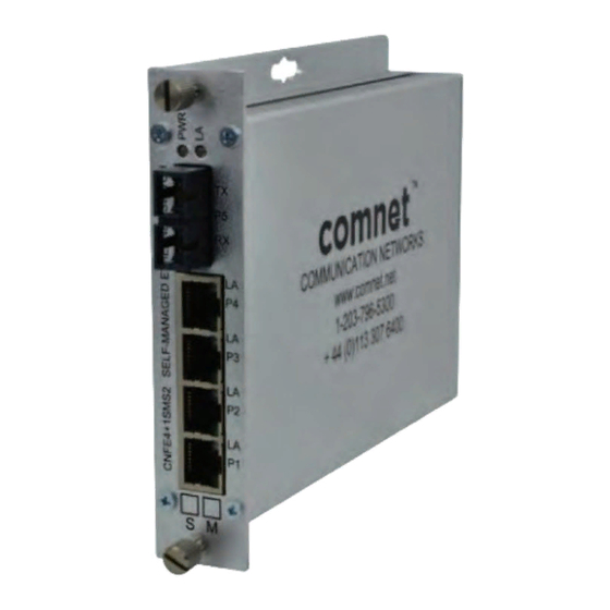
CNFE4+1SMS(M,S)2
FOUR PORT 10/100T(X) + ONE PORT 100FX
EThERNET SElF-MANAGEd SwITCh
The ComNet
CNFE4+1SMS(M,S)2 is a five-port self-managed Ethernet switch with
™
uplink management functionality. It provides four ports operating at 10/100Mbps
and is designed to combine Ethernet data from the four electrical ports into a single
optical port and forward that data to the next network device, using two-fiber ST or
SC optical connectors. There is no programming required to use this switch. The
ComNet CNFE4+1SMS comes pre-programmed, preventing network video flooding
with dIP switch selection of the fiber port as uplink or as an unmanaged switch It is
"Plug-and-Play" easy to use.
Led Indicators confirm the operating status of this device. See Figure 4 on Page 3
for an explanation of the indicators.
The ComNet CNFE4+1SMS may be either wall mounted, rack mounted ("ComFit"
packaging) or dIN-rail mounted with the use of the ComNet dINBKT1 adapter. See
Figure A on Page 4 for mounting instructions.
See Figures 1 – 5 for complete installation details.
INS_CNFE4+1SMS(M,S)2_REVA 07/08/11 PAGE 1
Advertisement
Table of Contents

Related Manuals for Comnet CNFE4+1SMSM2


Summary of Contents for Comnet CNFE4+1SMSM2
- Page 1 The ComNet CNFE4+1SMS may be either wall mounted, rack mounted (“ComFit” packaging) or dIN-rail mounted with the use of the ComNet dINBKT1 adapter. See Figure A on Page 4 for mounting instructions. See Figures 1 – 5 for complete installation details.
- Page 2 INSTALLATION AND OPERATION MANUAL CNFE4+1SMS(MS)2 FIGURE 1 – CNFE4+1SMS OPTICAL FIBER RJ-45 RJ-45 RJ-45 RJ-45 BLACK BLACK WITH WHITE STRIPE Power Supply: Surface Mount: 9–24VDC@1A Rack Mount: From Rack NOTE: Remove Electrical Connector for Rack Mount Units FIGURE 2 – CNFE4+1SMS FIGURE 3 –...
- Page 3 INSTALLATION AND OPERATION MANUAL CNFE4+1SMS(MS)2 FIGURE 4 – LED INDICATORS LINK (P5) LINK (P1 – P4) SOLID link Up link Up Power Applied BLINKING data Activity data Activity – No data link No data link Power Not Applied FIGURE 5 – APPLICATION DIAGRAM WITH MULTICAST TRAFFIC IGMP Enabled on CNGE2FE24MODMS, Uplink enabled on the units CNGE2FE24MODMS CNFE4SMS...
- Page 4 8 TURNBERRy PARK ROAD | GILDERSOME | MORLEy | LEEDS, UK LS27 7LE T: +44 (0)113 307 6400 | F: +44 (0)113 253 7462 | INFO-EUROPE@COMNET.NET © 2012 Communications Networks Corporation. All Rights Reserved. “ComNet” and the “ComNet logo” are registered trademarks of Communication Networks, llC. INS_CNFE4+1SMS(M,S)2_REVA 07/08/11 PAGE 4...
Need help?
Do you have a question about the CNFE4+1SMSM2 and is the answer not in the manual?
Questions and answers