Sign In
Upload
Download
Table of Contents
Contents
Add to my manuals
Delete from my manuals
Share
URL of this page:
HTML Link:
Bookmark this page
Add
Manual will be automatically added to "My Manuals"
Print this page
×
Bookmark added
×
Added to my manuals
Manuals
Brands
Allen-Bradley Manuals
Controller
MicroLogix 1100
Instruction set reference manual
Allen-Bradley MicroLogix 1100 Instruction Set Reference Manual
Hide thumbs
Also See for MicroLogix 1100
:
User manuals
(30 pages)
,
User manual
(256 pages)
1
2
3
4
Table Of Contents
5
6
7
8
9
10
11
12
13
14
15
16
17
18
19
20
21
22
23
24
25
26
27
28
29
30
31
32
33
34
35
36
37
38
39
40
41
42
43
44
45
46
47
48
49
50
51
52
53
54
55
56
57
58
59
60
61
62
63
64
65
66
67
68
69
70
71
72
73
74
75
76
77
78
79
80
81
82
83
84
85
86
87
88
89
90
91
92
93
94
95
96
97
98
99
100
101
102
103
104
105
106
107
108
109
110
111
112
113
114
115
116
117
118
119
120
121
122
123
124
125
126
127
128
129
130
131
132
133
134
135
136
137
138
139
140
141
142
143
144
145
146
147
148
149
150
151
152
153
154
155
156
157
158
159
160
161
162
163
164
165
166
167
168
169
170
171
172
173
174
175
176
177
178
179
180
181
182
183
184
185
186
187
188
189
190
191
192
193
194
195
196
197
198
199
200
201
202
203
204
205
206
207
208
209
210
211
212
213
214
215
216
217
218
219
220
221
222
223
224
225
226
227
228
229
230
231
232
233
234
235
236
237
238
239
240
241
242
243
244
245
246
247
248
249
250
251
252
253
254
255
256
257
258
259
260
261
262
263
264
265
266
267
268
269
270
271
272
273
274
275
276
277
278
279
280
281
282
283
284
285
286
287
288
289
290
291
292
293
294
295
296
297
298
299
300
301
302
303
304
305
306
307
308
309
310
311
312
313
314
315
316
317
318
319
320
321
322
323
324
325
326
327
328
329
330
331
332
333
334
335
336
337
338
339
340
341
342
343
344
345
346
347
348
349
350
351
352
353
354
355
356
357
358
359
360
361
362
363
364
365
366
367
368
369
370
371
372
373
374
375
376
377
378
379
380
381
382
383
384
385
386
387
388
389
390
391
392
393
394
395
396
397
398
399
400
401
402
403
404
405
406
407
408
409
410
411
412
413
414
415
416
417
418
419
420
421
422
423
424
425
426
427
428
429
430
431
432
433
434
435
436
437
438
439
440
441
442
443
444
445
446
447
448
449
450
451
452
453
454
455
456
457
458
459
460
461
462
463
464
465
466
467
468
469
470
471
472
473
474
475
476
477
478
479
480
481
482
483
484
485
486
487
488
489
490
491
492
493
494
495
496
497
498
499
500
501
502
503
504
505
506
507
508
509
510
511
512
513
514
515
516
517
518
519
520
521
522
523
524
525
526
527
528
529
530
531
532
533
534
535
536
537
538
539
540
541
542
543
544
545
546
547
548
549
550
551
552
553
554
555
556
557
558
559
560
561
562
563
564
565
566
567
568
569
570
571
572
573
574
575
576
577
578
579
580
581
582
583
584
585
586
587
588
589
590
591
592
593
594
595
596
597
598
599
600
601
602
603
604
605
606
607
608
609
610
611
612
613
614
615
616
page
of
616
Go
/
616
Contents
Table of Contents
Bookmarks
Table of Contents
Firmware Revision History
Firmware Upgrades
Summary of Changes
Table of Contents
Embedded I/O
Micrologix 1100 Expansion I/O
Micrologix 1100 Expansion I/O Memory Mapping
I/O Addressing
I/O Forcing
Input Filtering
Analog Inputs
Latching Inputs
Configuring Expansion
I/O Using Rslogix 500
Common Techniques Used in this Manual
Preface
Purpose of this Manual
Who Should Use this Manual
Related Documentation
Rockwell Automation Support
Chapter 1 Controller Memory
Data Files
Types Data Files
Protecting Data Files During Download
Static File Protection
Password Protection
Clearing the Controller Memory
Allow Future Access Setting (OEM Lock)
Web View Disable (os Series B FRN 4 or Later)
Chapter 2 Overview
Chapter 2 Function Files Overview
Real-Time Clock Function File
RTA - Real Time Clock Adjust Instruction
Memory Module Information Function File
Base Hardware Information Function File
Communications Status File
Ethernet Communications Status File
Input/Output Status File
Publication 1763-RM001C-EN-P - October
Instruction Set
Using the Instruction Descriptions
Chapter 4 High-Speed Counter Overview
Programmable Limit Switch Overview
High-Speed Counter (HSC) Function File
High-Speed Counter Function File Sub-Elements Summary
HSC Function File Sub-Elements
HSL - High-Speed Counter Load
RAC - Reset Accumulated Value
Programmable Limit Switch (PLS) File
PTO - Pulse Train Output
Chapter 5
Pulse Train Output Function
Pulse Train Outputs (PTO) Function File
Pulse Train Output Function File Sub-Elements Summary
PWM - Pulse Width Modulation
PWM Function
Pulse Width Modulation (PWM) Function File
Pulse Width Modulated Function File Elements Summary
XIC - Examine if Closed XIO - Examine if Open
Chapter 6
OTE - Output Energize
OTL - Output Latch OTU - Output Unlatch
ONS - One Shot
OSR - One Shot Rising OSF - One Shot Falling
Chapter 7
Timer Instructions Overview
TON - Timer, On-Delay
TOF - Timer, Off-Delay
RTO - Retentive Timer, On-Delay
How Counters Work
CTU - Count up CTD - Count down
RES - Reset
Chapter 8
Using the Compare Instructions
EQU - Equal NEQ - Not Equal
GRT - Greater than LES - Less than
GEQ - Greater than or Equal to LEQ - Less than or Equal to
MEQ - Mask Compare for Equal
LIM - Limit Test
Math Instructions
Chapter 9 Using the Math Instructions
Updates to Math Status Bits
Using the Floating Point (F) Data File
ADD - Add SUB - Subtract
MUL - Multiply
DIV - Divide
NEG - Negate
CLR - Clear
ABS - Absolute Value
SCL - Scale
SCP - Scale with Parameters
SQR - Square Root
Chapter 10 Using Decode and Encode Instructions
DCD - Decode 4 to 1-Of-16
ENC - Encode 1-Of-16 to 4
FRD - Convert from Binary Coded Decimal (BCD)
TOD - Convert to Binary Coded Decimal (BCD)
GCD - Gray Code
Conversion Instructions
Chapter 11 Using Logical Instructions
Updates to Math Status Bits
AND - Bit-Wise and
OR - Logical or
XOR - Exclusive or
NOT - Logical NOT
Logical Instructions
Chapter 12 MOV - Move
MVM - Masked Move
Publication 1763-RM001C-EN-P - October
Move Instructions
File Instructions
Chapter 13 CPW - Copy Word
COP - Copy File
FLL - Fill File
BSL - Bit Shift Left
BSR - Bit Shift Right
FFL - First In, First out (FIFO) Load
FFU - First In, First out (FIFO) Unload
LFL - Last In, First out (LIFO) Load
LFU - Last In, First out (LIFO) Unload
SWP - Swap
Chapter 14 SQC- Sequencer Compare
Chapter 14 Sequencer Instructions SQC- Sequencer Compare
SQO- Sequencer Output
SQL - Sequencer Load
Chapter 15 JMP - Jump to Label
LBL - Label
JSR - Jump to Subroutine
SBR - Subroutine Label
RET - Return from Subroutine
SUS - Suspend
TND - Temporary End
END - Program End
MCR - Master Control Reset
Input and Output Instructions IIM - Immediate Input with Mask
Chapter 16
IOM - Immediate Output with Mask
REF- I/O Refresh
Chapter 17 Information about Using Interrupts
User Interrupt Instructions
INT - Interrupt Subroutine
STS - Selectable Timed Start
UID - User Interrupt Disable
UIE - User Interrupt Enable
UIF - User Interrupt Flush
Using the Selectable Timed Interrupt (STI) Function File
Using the Event Input Interrupt (EII) Function File
Publication 1763-RM001C-EN-P - October
Chapter 18 The PID Concept
The PID Equation
PD Data File
PID - Proportional Integral Derivative
Input Parameters
Output Parameters
Tuning Parameters
Runtime Errors
Analog I/O Scaling
Application Notes
Application Examples
Process Control Instruction
Chapter 19 General Information
Instruction Types and Operation
Protocol Overview
String (ST) Data File
Control Data File
ACL - ASCII Clear Buffers
AIC - ASCII Integer to String
AWA - ASCII Write with Append
AWT - ASCII Write
ABL - Test Buffer for Line
ACB - Number of Characters in Buffer
ACI - String to Integer
ACN - String Concatenate
AEX - String Extract
AHL - ASCII Handshake Lines
ARD - ASCII Read Characters
ARL - ASCII Read Line
ASC - String Search
ASR - ASCII String Compare
Timing Diagram for ARD, ARL, AWA, and AWT Instructions
Using In-Line Indirection
ASCII Instruction Error Codes
ASCII Character Set
ASCII Instructions
Communications Instructions Messaging Overview
Chapter 20
SVC - Service Communications
MSG - Message
The Message Element
Timing Diagram for the MSG Instruction
Communication Servicing Selection and Message Servicing Selection
MSG Instruction Ladder Logic
Local Messages
Configuring a Local Message
Local Messaging Examples
Remote Messages
Configuring a Remote Message
Configuring a Multi-Hop Remote Message on Ethernet/Ip Communication Channel
Configuring a Micrologix 1100 CIP Generic Message Via Ethernet (os Series B FRN 4 or Later)
MSG Instruction Error Codes
Special Function with MSG Instruction (os Series B FRN 4 or Later)
Configure MSG Setup Screen to Send SMTP Message
Chapter 21 RCP - Recipe
Data Logging
Queues and Records
Configuring Data Log Queues
DLG - Data Log Instruction
Data Log Status File
Retrieving (Reading) Records
Accessing the Retrieval File
Conditions that will Erase the Data Retrieval File
Chapter 22 LCD Overview
LCD Function File
LCD Function File Sub-Elements Summary
LCD Function File Sub-Elements
LCD - LCD Instruction
Programming Instructions Memory Usage and Execution Time
Appendix A Scan Time Worksheet
Appendix B Status File Overview
Status File Details
Publication 1763-RM001C-EN-P - October
Fault Messages and Error Codes
Identifying Controller Faults
Contacting Rockwell Automation for Assistance
Appendix D Communication Protocol
DF1 Full-Duplex Protocol
DF1 Half-Duplex Protocol
DF1 Radio Modem Protocol
Modbus RTU Protocol
ASCII Driver
Ethernet Driver
Knowledgebase Quick Starts # 17444 "Quick Start" Pulse Train Output (PTO)
17446 "Quick Start" Pulse Width Modulation (PWM)
17447 "Quick Start" High Speed Counter (HSC)
17465 "Quick Start" Message (MSG)
17501 "Quick Start" Selectable Timed Interrupt (STI)
17503 "Quick Start" Real Time Clock (RTC)
17558 "Quick Start" User Interrupt Disable (UID)
Appendix E 18465 "Quick Start" RTC Synchronization between Controllers
18498 "Quick Start" Data Logging (DLG)
Basic Requirements to Use 40Khz PTO and PWM in Micrologix Controller
Appendix F
PTO and PWM Function File Changes in Series B Controller
Rslogix500 Display Issues
Instruction Issues
Appendix 23 Binary Numbers
Hexadecimal Numbers
Hex Mask
Appendix H System Related
Serial Communications Related
Ethernet Communications Related
Application Layer Related
Embedded IO Configuration Related
Web-Server Related
Rslogix500 Compatibility
Publication 1763-RM001C-EN-P - October
Advertisement
Quick Links
1
Embedded I/O
2
Micrologix 1100 Expansion I/O
3
I/O Addressing
4
Analog Inputs
Download this manual
See also:
User Manual
efesotomasyon.com - Allen Bradley,Rockwell,plc,servo,drive
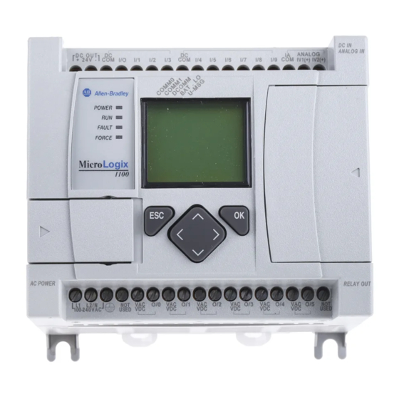
MicroLogix™ 1100
Programmable
Controllers
Bulletin 1763 Controllers and 1762
Expansion I/O
Instruction Set Reference
Manual
Table of
Contents
Previous
Page
Next
Page
1
2
3
4
5
Advertisement
Table of Contents
Need help?
Do you have a question about the MicroLogix 1100 and is the answer not in the manual?
Ask a question
Questions and answers
Related Manuals for Allen-Bradley MicroLogix 1100
Controller Allen-Bradley MicroLogix 1100 User Manual
(256 pages)
Server Allen-Bradley MicroLogix 1100 User Manuals
Embedded web server (30 pages)
Controller Allen-Bradley PLC-5 User Manual
Enhanced and ethernet plc-5 programmable controllers (388 pages)
Controller Allen-Bradley Ethernet PLC-5 Quick Start Manual
Ethernet plc-5 programmable controller (29 pages)
Controller Allen-Bradley 1336 PLUS Selection Manual
Digital ac drives in centerline motor control centers (26 pages)
Controller Allen-Bradley 1769 User Manual
Compactlogix (148 pages)
Controller Allen-Bradley 1756 ControlLogix Instruction Manual
Logix 5000 controllers (676 pages)
Controller Allen-Bradley LOGIX 5000 Reference Manual
Controllers advanced process control and drives and equipment phase and sequence instructions (561 pages)
Controller Allen-Bradley Logix 5000 Series Programming Manual
Nonvolatile memory card (35 pages)
Controller Allen-Bradley Logix 5000 Series Programming Manual
Controllers produced and consumed tags (48 pages)
Controller Allen-Bradley 1769-L16ER-BB1B User Manual
Compactlogix 5370 series (327 pages)
Controller Allen-Bradley MicroLogix 1400 User Manual
(404 pages)
Controller Allen-Bradley MicroLogix 1400 Instruction Manual
Programmable controllers (694 pages)
Controller Allen-Bradley MicroLogix 1200 User Manual
(162 pages)
Controller Allen-Bradley 1756-HYD02 User Manual
Motion coordinate system (236 pages)
Controller Allen-Bradley 1305 Series User Manual
Adjustable frequency ac drive 0.37 - 4 kw (0.5 - 5 hp) frn 6.01 and up (171 pages)
This manual is also suitable for:
1763-l16bbb
1763-l16awa
1763-l16bwa
1763-l16dwd
Table of Contents
Save PDF
Print
Rename the bookmark
Delete bookmark?
Delete from my manuals?
Login
Sign In
OR
Sign in with Facebook
Sign in with Google
Upload manual
Upload from disk
Upload from URL


Need help?
Do you have a question about the MicroLogix 1100 and is the answer not in the manual?
Questions and answers