Allen-Bradley MicroLogix 1100 User Manual
Hide thumbs
Also See for MicroLogix 1100:
- User manuals (30 pages) ,
- Instruction set reference manual (616 pages)
Table of Contents
Advertisement
Quick Links
See also:
User Manual
Advertisement
Table of Contents

Related Manuals for Allen-Bradley MicroLogix 1100


Summary of Contents for Allen-Bradley MicroLogix 1100
- Page 1 MicroLogix 1100 Programmable Controllers Bulletin 1763 Controllers and 1762 Expansion I/O User Manual...
- Page 2 BURN HAZARD alert people that surfaces may reach dangerous temperatures. Rockwell Automation, DeviceNet, ModBus, Allen-Bradley, SLC 5/02, SLC 5/03, PLC-5, MicroLogix, SLC 500, RSLogix, RSLinx, and RSLogix 500 are trademarks of Rockwell Automation, Inc. Trademarks not belonging to Rockwell Automation are property of their respective companies.
-
Page 3: Firmware Revision History
Summary of Changes To help you find new and updated information in this release of the manual, we have included change bars as shown to the right of this paragraph. The table below lists the sections that document new features and additional or updated information on existing features. - Page 4 Summary of Changes Publication 1763-UM001E-EN-P - June 2015...
-
Page 5: Table Of Contents
Component Descriptions........12 MicroLogix 1100 Memory Module and Built-in Real-Time Clock 12 1762 Expansion I/O . - Page 6 Table of Contents DIN Rail Mounting ........35 Panel Mounting .
- Page 7 Table of Contents Connecting the Communication Cable to the DH-485 Connector . Grounding and Terminating the DH-485 Network ... 87 Connecting the AIC+ ........89 Cable Selection Guide .
- Page 8 Analog Modules ........171 Appendix B MicroLogix 1100 Replacement Kits ......179 Replacement Parts Lithium Battery (1763-BA) .
- Page 9 Table of Contents Transportation ........181 Disposal .
- Page 10 MicroLogix 1100 Controllers and Ethernet Communication ..213 Connecting to Networks via MicroLogix 1100 Performance Considerations ....214 Ethernet Interface MicroLogix 1100 and PC Connections to the Ethernet Network .
-
Page 11: Preface
If you do not, obtain the proper training before using this product. This manual is a reference guide for MicroLogix 1100 controllers and Purpose of this Manual expansion I/O. It describes the procedures you use to install, wire, and troubleshoot your controller. -
Page 12: Related Documentation
Information on the MicroLogix 1100 Controllers instruction set. Set Reference Manual, publication 1763-RM001 MicroLogix 1100 Programmable Controllers Installation Information on mounting and wiring the MicroLogix 1100 Controllers, including Instructions, publication 1763-IN001 a mounting template for easy installation. Advanced Interface Converter (AIC+) User Manual, A description on how to install and connect an AIC+. -
Page 13: Hardware Overview
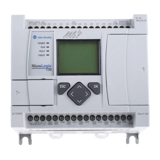
Chapter Hardware Overview The Bulletin 1763, MicroLogix 1100 programmable controller contains a Hardware Features power supply, input and output circuits, a processor, an isolated combination RS-232/485 communication port, and an Ethernet port. Each controller supports 18 I/O points (10 digital inputs, 2 analog inputs, and 6 discrete outputs). -
Page 14: Component Descriptions
The 4 high-speed inputs (inputs 0 through 3) can be used individually for pulse catch/latching inputs or combined as a high speed counter. Refer to Digital Input Specifications on page 155 and the MicroLogix 1100 Instruction Set Reference Manual, publication 1763-RM001, for more information. -
Page 15: 1762 Expansion I/O
Hardware Overview 1763-MM1 Memory Module 1762 Expansion I/O 1762 expansion I/O can be connected to the MicroLogix 1100 controller, as shown below. A maximum of four I/O modules, in any combination, can be connected to a controller. See Appendix G to determine how much heat a certain combination generates. -
Page 16: Communication Cables
1762-IR4 4-Channel RTD/Resistance Input Module 1762-IT4 4-Channel Thermocouple/mV Input Module Use only the following communication cables with the MicroLogix 1100 Communication Cables controllers. These cables are required for Class I Div. 2 applications. • 1761-CBL-AM00 Series C or later • 1761-CBL-AP00 Series C or later •... - Page 17 Hardware Overview UNSUPPORTED CONNECTION ATTENTION Do not connect a MicroLogix 1100 controller to another MicroLogix family controller such as MicroLogix 1000, MicroLogix 1200, MicroLogix 1500, or the network port of a 1747-DPS1 Port Splitter using a 1761- CBL-AM00 (8-pin mini-DIN to 8-pin mini-DIN) cable or equivalent.
-
Page 18: Programming
Communication Options isolated combination RS-232/485 communication port (Channel 0) and an Ethernet port (Channel 1). The isolated Channel 0 port on the MicroLogix 1100 can be connected to the following: • operator interfaces, personal computers, etc. using DF1 Full Duplex point-to-point •... - Page 19 Hardware Overview The controller cannot be used for CIP implicit messaging (real-time I/O messaging). The controller also includes an embedded web server which allows viewing of not only module information, TCP/IP configuration, and diagnostic information, but also includes the data table memory map and data table monitor screen using a standard web browser.
- Page 20 Hardware Overview Notes: Publication 1763-UM001E-EN-P - June 2015...
-
Page 21: Installing Your Controller
Chapter Installing Your Controller This chapter shows you how to install your controller. The only tools you require are a flat or Phillips head screwdriver and drill. Topics include: • agency certifications • compliance to European Union Directives • installation considerations •... -
Page 22: Emc Directive
Part 2 - Equipment Requirements and Tests. For specific information required by EN 61131-2, see the appropriate sections in this publication, as well as the following Allen-Bradley publications: • Industrial Automation Wiring and Grounding Guidelines for Noise Immunity, publication 1770-4.1 •... -
Page 23: Safety Considerations
Installing Your Controller Electrostatic discharge can damage semiconductor devices ATTENTION inside the controller. Do not touch the connector pins or other sensitive areas. Vertical mounting of the controller is not supported due to ATTENTION heat build-up considerations. Be careful of metal chips when drilling mounting holes for ATTENTION your controller or other equipment within the enclosure or panel. - Page 24 Installing Your Controller EXPLOSION HAZARD WARNING • Substitution of components may impair suitability for Class I, Division 2. • Do not replace components or disconnect equipment unless power has been switched off. • Do not connect or disconnect components unless power has been switched off.
-
Page 25: Disconnecting Main Power
Installing Your Controller Disconnecting Main Power Explosion Hazard WARNING Do not replace components, connect equipment, or disconnect equipment unless power has been switched off. The main power disconnect switch should be located where operators and maintenance personnel have quick and easy access to it. In addition to disconnecting electrical power, all other sources of power (pneumatic and hydraulic) should be de-energized before working on a machine or process controlled by a controller. -
Page 26: Periodic Tests Of Master Control Relay Circuit
(VA). Power Supply Inrush During power-up, the MicroLogix 1100 power supply allows a brief inrush current to charge internal capacitors. Many power lines and control transformers can supply inrush current for a brief time. If the power source cannot supply this inrush current, the source voltage may sag momentarily. -
Page 27: Loss Of Power Source
Installing Your Controller Loss of Power Source The power supply is designed to withstand brief power losses without affecting the operation of the system. The time the system is operational during power loss is called program scan hold-up time after loss of power. The duration of the power supply hold-up time depends on the type and state of the I/O, but is typically between 10 milliseconds and 3 seconds. -
Page 28: Master Control Relay
Installing Your Controller Do not bring in unfiltered outside air. Place the controller in an enclosure to protect it from a corrosive atmosphere. Harmful contaminants or dirt could cause improper operation or damage to components. In extreme cases, you may need to use air conditioning to protect against heat build-up within the enclosure. -
Page 29: Using Emergency-Stop Switches
Installing Your Controller The master control relay is not a substitute for a disconnect to the controller. It is intended for any situation where the operator must quickly de-energize I/O devices only. When inspecting or installing terminal connections, replacing output fuses, or working on equipment within the enclosure, use the disconnect to shut off power to the rest of the system. -
Page 30: Schematic (Using Iec Symbols)
Installing Your Controller Schematic (Using IEC Symbols) 230V AC Disconnect Fuse 230V AC Circuits Isolation Operation of either of these contacts will Transformer remove power from the external I/O Master Control Relay (MCR) circuits, stopping machine motion. 115V AC Cat. No. 700-PK400A1 or 230V AC Emergency-Stop Suppressor... -
Page 31: Schematic (Using Ansi/Csa Symbols)
Installing Your Controller Schematic (Using ANSI/CSA Symbols) 230V AC Disconnect Fuse 230V AC Output Circuits Isolation Operation of either of these contacts will Transformer remove power from the external I/O Master Control Relay (MCR) circuits, stopping machine motion. 115V AC or Cat. -
Page 32: Installing A Memory Module
Installing Your Controller 1. Remove the memory module port cover. Installing a Memory Module 2. Align the connector on the memory module with the connector pins on the controller. 3. Firmly seat the memory module into the controller. Publication 1763-UM001E-EN-P - June 2015... -
Page 33: Using The Battery
Installing Your Controller The MicroLogix 1100 controller is equipped with a replaceable battery. The Using the Battery Battery Low indicator on the LCD display of the controller shows the status of the replaceable battery. When the battery is low, the indicator is set (displayed as a solid rectangle). -
Page 34: Connecting The Battery Wire Connector
Installing Your Controller Connecting the Battery Wire Connector Follow the procedure below to connect the battery wire connector to the battery connector. 1. Insert the replaceable battery wire connector into the battery connector. 2. Secure the battery connector wires along the wire guide as shown below. Replaceable Battery Pocket Replaceable Battery Wire Guide... -
Page 35: Controller Mounting Dimensions
Installing Your Controller Controller Mounting Dimensions 1763-L16AWA, 1763-L16BWA, 1763-L16BBB Controller Dimensions Dimension 1763-L16AWA 1763-L16BWA 1763-L16BBB 1763-L16DWD 90 mm (3.5 in.) 110 mm (4.33 in.) 87 mm (3.43 in.) The controller mounts horizontally, with the expansion I/O extending to the Controller and Expansion right of the controller. -
Page 36: Mounting The Controller
Installing Your Controller MicroLogix 1100 controllers are suitable for use in an industrial environment Mounting the Controller when installed in accordance with these instructions. Specifically, this equipment is intended for use in clean, dry environments (Pollution degree ) and to circuits not exceeding Over Voltage Category II (IEC 60664-1). -
Page 37: Din Rail Mounting
Installing Your Controller DIN Rail Mounting The maximum extension of the latch is 14 mm (0.55 in.) in the open position. A flat-blade screwdriver is required for removal of the controller. The controller can be mounted to EN50022-35x7.5 or EN50022-35x15 DIN rails. DIN rail mounting dimensions are shown below. -
Page 38: Panel Mounting
Mount to panel using #8 or M4 screws. To install your controller using mounting screws: 1. Remove the mounting template from inside the back cover of the MicroLogix 1100 Programmable Controllers Installation Instructions, publication 1763-IN001. 2. Secure the template to the mounting surface. (Make sure your controller is spaced properly. -
Page 39: 1762 Expansion I/O Dimensions
Installing Your Controller 1762 Expansion I/O Dimensions Dimension Expansion I/O Module 90 mm (3.5 in.) 40 mm (1.57 in.) 87 mm (3.43 in.) Mounting 1762 Expansion During panel or DIN rail mounting of all devices, be sure ATTENTION that all debris (metal chips, wire stands, etc.) is kept from falling into the module. -
Page 40: Panel Mounting
Installing Your Controller Use DIN rail end anchors (Allen-Bradley part number 1492-EA35 or 1492-EAH35) for vibration or shock environments. The following illustration shows the location of the end anchors. End Anchor End Anchor 1762 expansion I/O must be mounted horizontally as illustrated. -
Page 41: Connecting Expansion I/O
Installing Your Controller The expansion I/O module is attached to the controller or another I/O Connecting Expansion I/O module by means of a flat ribbon cable after mounting, as shown below. Use the pull loop on the connector to disconnect modules. Do not pull on the ribbon cable. - Page 42 Installing Your Controller Notes: Publication 1763-UM001E-EN-P - June 2015...
-
Page 43: Wiring Your Controller
Chapter Wiring Your Controller This chapter describes how to wire your controller and expansion I/O. Topics include: • wire requirements • using surge suppressors • grounding the controller • wiring diagrams • sinking and sourcing wiring diagrams • controller I/O wiring •... -
Page 44: Wiring The Terminal Block
Wiring torque = 0.56 Nm (5.0 in-lb) rated Wiring the Terminal Block The MicroLogix 1100 controllers have screw-cage clamps on the input and output terminal blocks. With screw-cage clamp terminal blocks, there is no need to attach additional hardware such as a spade lug to the wire, or use a finger-safe cover. -
Page 45: Using Surge Suppressors
Wiring Your Controller Screw-cage clamp terminal block Because of the potentially high current surges that occur when switching Using Surge Suppressors inductive load devices, such as motor starters and solenoids, the use of some type of surge suppression to protect and extend the operating life of the controllers output contacts is required. - Page 46 Suitable surge suppression methods for inductive AC load devices include a varistor, an RC network, or an Allen-Bradley surge suppressor, all shown below. These components must be appropriately rated to suppress the switching transient characteristic of the particular inductive device. See the table on 45 for recommended suppressors.
-
Page 47: Recommended Surge Suppressors
Wiring Your Controller Recommended Surge Suppressors Use the Allen-Bradley surge suppressors shown in the following table for use with relays, contactors, and starters. Recommended Surge Suppressors Device Coil Voltage Suppressor Catalog Number Bulletin 509 Motor Starter 120V AC 599-K04 Bulletin 509 Motor Starter... -
Page 48: Grounding The Controller
Wiring Your Controller In solid-state control systems, grounding and wire routing helps limit the Grounding the Controller effects of noise due to electromagnetic interference (EMI). Run the ground connection from the ground screw of the controller to the ground bus prior to connecting any devices. -
Page 49: Wiring Diagrams
Wiring Your Controller The following illustrations show the wiring diagrams for the MicroLogix 1100 Wiring Diagrams controllers. Controllers with DC inputs can be wired as either sinking or sourcing inputs. (Sinking and sourcing does not apply to AC inputs.) Refer to Sinking and Sourcing Wiring Diagrams on page 3-50. - Page 50 Wiring Your Controller 1763-L16BWA Group 0 Group 1 Group 2 DC OUT IV1(+) IV2(+) Input Terminal Block Output Terminal Block L2/N 100-240 VAC USED USED The 24V DC sensor supply of the 1763-L16BWA should ATTENTION not be used to power output circuits. It should only be used to power input devices (e.g.
-
Page 51: Terminal Groupings
Wiring Your Controller Terminal Groupings Input Terminal Grouping Controller Inputs Input Group Common Terminal Input Terminal Group 0 AC COM 0 I/0 through I/3 1763-L16AWA Group 1 AC COM 1 I/4 through I/9 Group 2 IA COM IV1(+) and IV2(+) Group 0 DC COM 0 I/0 through I/3... -
Page 52: Sinking And Sourcing Wiring Diagrams
Wiring Your Controller Any of the MicroLogix 1100 DC embedded input groups can be configured as Sinking and Sourcing sinking or sourcing depending on how the DC COM is wired on the group. Wiring Diagrams Refer to pages 51 through 51 for sinking and sourcing wiring diagrams. - Page 53 Wiring Your Controller 1763-L16BWA Sinking Input Wiring Diagram +DCa +DCb 24V DC Sensor Power -DCa -DCb DC OUT + 24V IV1(+) IV2(+) 1763-L16BWA Sourcing Input Wiring Diagram -DCa -DCb 24V DC Sensor Power +DCa +DCb DC OUT + 24V IV1(+) IV2(+) 1763-L16BBB and 1763-L16DWD Sinking Input Wiring Diagram +DCa...
- Page 54 Wiring Your Controller 1763-L16AWA and 1763-L16BWA Output Wiring Diagram +DCa -DCa L2/N 100-240 VAC USED USED 1763-L16BBB Output Wiring Diagram -DCc +DCa -DCa +DCb -DCb +DCc + 24V - DC IN USED USED USED 24V+ 24V- USED 1763-L16DWD Output Wiring Diagram +DCa -DCa 12/24V...
-
Page 55: Controller I/O Wiring
To help reduce the effects of environmental noise, install the MicroLogix 1100 system in a properly rated (for example, NEMA) enclosure. Make sure that the MicroLogix 1100 system is properly grounded. -
Page 56: Minimizing Electrical Noise On Analog Channels
Several specific steps can be taken to help reduce the effects of environmental noise on analog signals: • install the MicroLogix 1100 system in a properly rated (i.e., NEMA) enclosure. Make sure that the MicroLogix 1100 system is properly grounded. -
Page 57: Grounding Your Analog Cable
Wiring Your Controller Grounding Your Analog Cable Use shielded communication cable (Belden #8761). The Belden cable has two signal wires (black and clear), one drain wire, and a foil shield. The drain wire and foil shield must be grounded at one end of the cable. Foil shield Black wire Insulation... -
Page 58: Expansion I/O Wiring
Wiring Your Controller Expansion I/O Wiring Digital Wiring Diagrams The following illustrations show the digital expansion I/O wiring diagrams. 1762-IA8 Wiring Diagram IN 0 IN 1 IN 2 IN 3 100/120V ac IN 4 IN 5 IN 6 IN 7 Common connected internally. - Page 59 Wiring Your Controller 1762-IQ16 Wiring Diagram +DC (Sinking) -DC (Sourcing) IN 0 IN 1 IN 2 IN 3 24V dc IN 4 IN 5 IN 6 IN 7 -DC (Sinking) COM 0 +DC (Sourcing) +DC (Sinking) -DC (Sourcing) IN 8 IN 9 IN 10 IN 11...
- Page 60 Wiring Your Controller 1762-IQ32T Wiring Diagram 44920 1762-OA8 Wiring Diagram OUT 0 OUT 1 OUT 2 OUT 3 OUT 4 OUT 5 OUT 6 OUT 7 Publication 1763-UM001E-EN-P - June 2015...
- Page 61 Wiring Your Controller 1762-OB8 Wiring Diagram +VDC OUT 0 OUT 1 OUT 2 OUT 3 OUT 4 OUT 5 24V dc (source) OUT 6 OUT 7 DC COM 1762-OB16 Wiring Diagram VDC+ OUT 0 OUT 1 OUT 2 OUT 3 OUT 4 OUT 5 OUT 6...
- Page 62 Wiring Your Controller 1762-OB32T Wiring Diagram 44925 1762-OV32T Wiring Diagram 44915 Publication 1763-UM001E-EN-P - June 2015...
- Page 63 Wiring Your Controller 1762-OW8 Wiring Diagram L1 VAC1 + VAC-VDC 1 OUT 0 L2 DC1 COM OUT 1 OUT 2 OUT3 L1 VAC2 + VAC-VDC2 OUT 4 L2 DC2 COM OUT 5 OUT 6 OUT 7 1762-OW16 Wiring Diagram VAC-VDC OUT 0 OUT 1 OUT 2...
- Page 64 Wiring Your Controller 1762-OX6I Wiring Diagram L1-0 L1 OR +DC OUT0 N.C. L2 OR -DC OUT0 N.O. L1 OR +DC L1-1 OUT1 N.C. OUT1 N.O. L2 OR -DC L1-2 L1 OR +DC OUT2 N.C. L2 OR -DC OUT2 N.O. L1-3 L1 OR +DC OUT3 N.C.
-
Page 65: Analog Wiring
Wiring Your Controller 1762-IQ8OW6 Wiring Diagram +DC (Sinking) -DC (Sourcing) IN 0 IN 1 IN 2 IN 3 -DC (Sinking) +DC (Sourcing) COM 0 +DC (Sinking) IN 4 -DC (Sourcing) IN 5 IN 6 IN 7 -DC (Sinking) COM 1 +DC (Sourcing) Connected Internally L1 or +DC... - Page 66 Select the input type, current or voltage, using the switches located on the module’s circuit board and the input type/range selection bits in the Configuration Data File. Refer to MicroLogix 1100 Programmable Controllers Instruction Set Reference Manual, publication 1763-RM001. You can access the switches through the ventilation slots on the top of the module.
- Page 67 Wiring Your Controller 1762-IF2OF2 Wiring The following illustration shows the 1762-IF2OF2 analog expansion I/O terminal block. 1762-IF2OF2 Terminal Block Layout IN 0 (+) IN 0 (-) IN 1 (+) IN 1 (-) V Out 0 I Out 0 V Out 1 I Out 1 Common connected internally.
- Page 68 Select the input type, current or voltage, using the switches located on the module’s circuit board and the input type/range selection bits in the Configuration Data File. Refer to MicroLogix 1100 Programmable Controllers Instruction Set Reference Manual, publication 1763-RM001. You can access the switches through the ventilation slots on the top of the module.
- Page 69 Wiring Your Controller 1762-IF4 Terminal Block Layout IN 0 (+) IN 0 (-) IN 1 (+) IN 1 (-) IN 2 (+) IN 2 (-) IN 3 (+) IN 3 (-) Commons internally connected. Differential Sensor Transmitter Types IN 0 (+) Analog Sensor IN 0 (-) IN 1 (+)
- Page 70 Wiring Your Controller Sensor/Transmitter Types 2-Wire Transmitter Transmitter Module Power IN + Supply IN - Transmitter 3-Wire Transmitter Module Supply Signal IN + Power IN - Supply Transmitter 4-Wire Transmitter Module Supply Signal IN + Power IN - Supply (1) All power supplies rated N.E.C. Class 2. 1762-OF4 Output Type Selection The output type selection, current or voltage, is made by wiring to the appropriate terminals, Iout or Vout, and by the type/range selection bits in the...
- Page 71 Wiring Your Controller 1762-OF4 Wiring I out 0 Current Load I out 1 I out 2 I out 3 V out 0 Voltage Load V out 1 V out 2 V out 3 Publication 1763-UM001E-EN-P - June 2015...
- Page 72 Wiring Your Controller Notes: Publication 1763-UM001E-EN-P - June 2015...
-
Page 73: Communication Connections
(message exchange). MicroLogix 1100 controllers do not support Ethernet I/O master capability through CIP implicit messaging (real-time I/O messaging). For more information on MicroLogix 1100 communications, refer to the MicroLogix 1100 Programmable Controllers Instruction Set Reference Manual, publication 1763-RM001. -
Page 74: Default Communication Configuration
Communication Connections The MicroLogix 1100 communication Channel 0 has the following default Default Communication communication configuration. Configuration For Channel 0, the default configuration is present when: • The controller is powered-up for the first time. • The communications toggle functionality specifies default communications (specified using the LCD Display. -
Page 75: Changing Communication Configuration
Communication Connections indicator on the LCD display operates to show when the controller is in the default communications mode (settings shown on 72). The Communication Toggle Functionality only affects the communication configuration of Channel 0. Changing Communication Configuration Follow the procedure below to change from the user-defined communication configuration to the default communications mode and back. - Page 76 Communication Connections 2. Then, press the OK key on the LCD keypad. The Advanced Settings Menu screen is displayed, as shown below. 3. Select DCOMM Cfg using the Up and Down keys, as shown below, and then press the OK key. 4.
- Page 77 Communication Connections If the communication configuration is set to the default communication mode, the DCOMM Configuration screen is displayed as shown below. The DCOMM status indicator is displayed in solid rectangle. 5. Use the up arrow to change the indicator position so that it is pointing to Enable.Press the OK key to change to the default communication mode.
-
Page 78: Connecting To The Rs-232 Port
Communication Connections 6. Press the ESC key to return to the Advanced Settings Menu screen, as shown in step There are two ways to connect the MicroLogix™ 1100 programmable Connecting to the RS-232 controller to your personal computer using the DF1 protocol: using a Port point-to-point connection, or using a modem. -
Page 79: Making A Df1 Point-To-Point Connection
Channel 0. The recommended protocol for this configuration is DF1 Full-Duplex. You can connect a MicroLogix 1100 controller to your personal computer directly without using an external optical isolator, such as Advanced Interface Converter (AIC+), catalog number 1761-NET-AIC, as shown in the illustration below, because Channel 0 is isolated within the controller. -
Page 80: Using A Modem
(straight-through) (1) Series C or later cables are required for Class I Div 2 applications. You can connect a MicroLogix 1100 controller to your modem directly without using an external optical isolator, such as AIC+, catalog number 1761-NET-AIC, as shown in the illustration below, because Channel 0 is isolated within the controller. - Page 81 Communication Connections MicroLogix 1100 Channel 0 to Modem Cable Pinout When connecting MicroLogix 1100 Channel 0 to a modem using an RS-232 cable, the maximum that the cable length may be extended is 15.24 m (50 ft). DTE Device DCE Device...
-
Page 82: Connecting To A Df1 Half-Duplex Network
Communication Connections Connecting to a DF1 Half-Duplex Network When a communication port is configured for DF1 Half-Duplex Slave, available parameters include the following: DF1 Half-Duplex Configuration Parameters Parameter Options Baud Rate 300, 600, 1200, 2400, 4800, 9600, 19.2 KBps, 38.4 KBps Parity none, even Node Address... - Page 83 Communication Connections DF1 Half-Duplex Master-Slave Network Use the following diagram for DF1 Half-Duplex Master-Slave protocol without hardware handshaking. SLC 5/03 MicroLogix 1100 processor Master 1761-CBL-AM00 or 1761-CBL-HM02 1761-CBL-AP00 or 1761-CBL-PM02 DF1 Slave radio modem or lease line AIC+ AIC+ straight 9-25 pin cable...
- Page 84 Rockwell Software RSLinx 2.0 (or higher), SLC 5/03, SLC 5/04, DF1 Half-Duplex Protocol SLC 5/05, PLC-5, or MicroLogix Modem 1000, 1200, and 1500 processors configured for DF1Half-Duplex Master. Rockwell Software RSLinx 2.5 required for MicroLogix 1100. TERM TERM TERM SHLD SHLD SHLD CHS GND...
-
Page 85: Connecting To A Dh-485 Network
Connecting to a DH-485 MicroLogix 1100 controllers to the DH-485 network. Network You can connect a MicroLogix 1100 controller to your DH-485 network directly without using an external optical isolator, such as Advanced Interface Converter (AIC+), catalog number 1761-NET-AIC, as shown in the illustrations below, because Channel 0 is isolated within the controller. - Page 86 Communication Connections DH-485 Network with a MicroLogix 1100 Controller AIC+ AIC+ TERM TERM PanelView SHLD SHLD CHS GND CHS GND DC SOURCE DC SOURCE CABLE CABLE EXTERNAL EXTERNAL SLC 5/04 PanelView 550 DH-485 Network AIC+ AIC+ AIC+ AIC+ TERM TERM...
-
Page 87: Recommended Tools
Communication Connections Typical 3-Node Network (Channel 0 Connection) PanelView 550 PanelView RJ45 port 1761-CBL-AS09 or 1761-CBL-AS03 MicroLogix 1100 TERM SHLD CHS GND 1761-CBL-AM00 or 1761-CBL-HM02 DC SOURCE CABLE EXTERNAL 1747-CP3 or 1761-CBL-AC00 Recommended Tools To connect a DH-485 network to additional devices, you need tools to strip the shielded cable and to attach the cable to the AIC+ Advanced Interface Converter. -
Page 88: Connecting The Communication Cable To The Dh-485 Connector
Use these instructions for wiring the Belden #3106A or #9842 cable. (See Cable Selection Guide on page 90 if you are using standard Allen-Bradley cables.) Connecting the Communication Cable to the DH-485 Connector A daisy-chained network is recommended. Do not... -
Page 89: Grounding And Terminating The Dh-485 Network
Communication Connections Multiple Cable Connection When connecting multiple cables to the DH-485 connector, use the following diagram. to Previous Device to Next Device Connections using Belden #3106A Cable For this Wire/Pair Connect this Wire To this Terminal Shield/Drain Non-jacketed Terminal 2 - Shield Blue Blue Terminal 3 - (Common) - Page 90 Belden #3106A or #9842 Cable 1219 m (4000ft) Maximum Jumper MicroLogix 1100 Channel 0 to DH-485 Communication Cable Pinout When connecting MicroLogix 1100 Channel 0 to DH-485 communication cable pinout using an RS-232 cable, the maximum that the cable length may be extended is 15.24 m (50 ft).
-
Page 91: Connecting The Aic
Communication Connections You can connect a MicroLogix 1100 controller to a DH-485 network via Connecting the AIC+ Channel 0 directly without using an optical isolator, such as AIC+, catalog number 1761-NET-AIC, because Channel 0 is isolated. However, you need to use an AIC+ to connect your PC or other MicroLogix Family products, such as MicroLogix 1200, to a DH-485 network. -
Page 92: Cable Selection Guide
Communication Connections Cable Selection Guide 1761-CBL-PM02 1761-CBL-AP00 1761-CBL-PH02 Cable Length Connections from to AIC+ External Power Power Supply Selection Switch Required Setting 1761-CBL-AP00 45 cm (17.7 in.) SLC 5/03 or SLC 5/04 processors, ch 0 port 2 external 1761-CBL-PM02 2 m (6.5 ft) MicroLogix™... - Page 93 Communication Connections 1747-CP3 1761-CBL-AC00 Cable Length Connections from to AIC+ External Power Power Supply Selection Switch Required Setting 1747-CP3 3 m (9.8 ft) SLC 5/03 or SLC 5/04 processor, channel port 1 external 45 cm (17.7 in.) 1761-CBL-AC00 PC COM port port 1 external PanelView 550 through NULL modem...
- Page 94 Communication Connections 1761-CBL-PM02 Series C (or equivalent) Cable Wiring Diagram 6 8 7 Programming Controller Device 9-Pin D-Shell 8-Pin Mini Din Publication 1763-UM001E-EN-P - June 2015...
-
Page 95: Recommended User-Supplied Components
If you are making a cable to connect to port 2, you must configure your cable to connect to the Allen-Bradley cable shown above. In the 1761-CBL-PM02 cable, pins 4 and 6 are jumpered together within the DB-9 connector. -
Page 96: Safety Considerations
Communication Connections Safety Considerations This equipment is suitable for use in Class I, Division 2, Groups A, B, C, D or non-hazardous locations only. EXPLOSION HAZARD WARNING AIC+ must be operated from an external power source. This product must be installed in an enclosure. All cables connected to the product must remain in the enclosure or be protected by conduit or other means. -
Page 97: Powering The Aic
1761-NET-AIC, 1761-NET-ENI, and the 1761-NET-ENIW, these controllers provide the power for the interface converter modules. The MicroLogix 1100 does not provide 24V DC communication power. Instead these pins are used to provide RS-485 communications directly. Any AIC+, ENI, or ENIW not connected to a MicroLogix 1000, 1200, or 1500 controller requires a 24V DC power supply. - Page 98 Communication Connections Power Options Below are two options for powering the AIC+: • Use the 24V DC user power supply built into the MicroLogix™ 1000, 1200, or 1500 controller. The AIC+ is powered through a hard-wired connection using a communication cable (1761-CBL-HM02, or equivalent) connected to port 2.
-
Page 99: Connecting To Ethernet
Ethernet port (Channel 1). You do not need to use an Ethernet interface card, such as the Ethernet Interface (ENI) and (ENIW), catalog number 1761-NET-ENI and 1761-NET-ENIW, to connect your MicroLogix 1100 controller to an Ethernet network. For additional information on connecting... - Page 100 Communication Connections When to use straight-through and cross-over cable: • MicroLogix 1100 Ethernet port to 10/100Base-T Ethernet switch cables utilize a straight-through pin-out (1-1, 2-2, 3-3, 6-6). • Direct point-to-point 10/100 Base-T cables connecting the MicroLogix 1100 Ethernet port directly to another Ethernet port (or a computer 10/100Base-T port) require a cross-over pin-out (1-3, 2-6, 3-1, 6-2).
-
Page 101: Using The Lcd
Chapter Using the LCD This chapter describes how to use the LCD and keypad on the MicroLogix 1100 controller. Topics include: • operating principles • I/O status display • monitoring bit file • monitoring integer file • using the mode switch •... -
Page 102: Operating Principles
Using the LCD Operating Principles MicroLogix 1100 LCD Menu Structure Tree Startup Screen User Defined? Main Menu I/O Status Monitoring Integer Mode Switch User Displ KeyIn Mode Advance Set DCOMM Cfg ENET Cfg TrimPot Set System Info Fault Code User Defined Menu LCD Instruction Interface The ESC key is hold down more than 3 sec. -
Page 103: Startup Screen
The screen shown below is an example of a customized Startup screen. For more information on how to create and use a customized Startup screen, refer to the LCD Function File described in the MicroLogix 1100 Programmable Controllers Instruction Set Reference Manual, publication 1763-RM001. -
Page 104: Main Menu And Default Screen
Using the LCD Main Menu and Default Screen The Main menu consists of five menu items: I/O Status, Monitoring, Mode Switch, User Displ, and Advance Set. LCD Main Menu Publication 1763-UM001E-EN-P - June 2015... - Page 105 Using the LCD Main Menu Items Menu Item Description For details, refer to I/O Status Displays the I/O Status screen, which shows the I/O status I/O Status on page 5-107 of the embedded digital I/O. Monitoring Allows you to view and change the data value of a bit and an Monitoring Bit File on page 5-109 integer file.
-
Page 106: Operating Buttons
Using the LCD Operating Buttons Button Function Cursor Move cursor Buttons Select menu item Choose file numbers, values, etc. Next menu level, store your entry, apply the changes Previous menu level, cancel your entry Using Menus to Choose Values Press •... -
Page 107: Selecting Between Menu Items
Using the LCD Selecting Between Menu Items Cursor up or down Apply or Enter The symbol " " is used as the cursor. Cursor Display There are two different cursor types: Selection cursor (the symbol “ ”) is displayed left to the selected item. -
Page 108: Setting Values
Using the LCD Setting Values Change value = up/down arrows Move cursor between digits = left/right arrows Stores Entries Retain previous value Left/right arrow moves the cursor between the digits of the value (+02714). Up/down arrow changes the value. Up arrow = increment Down arrow = decrement Publication 1763-UM001E-EN-P - June 2015... -
Page 109: I/O Status
Using the LCD The MicroLogix 1100 provides I/O status indicators on the LCD screen. You I/O Status can view the status of inputs and outputs on the I/O Status screen on the LCD, as shown below. The I/O status indicators on this screen are updated every 100 ms to reflect the current I/O status in real time, regardless of controller scan time. -
Page 110: Viewing I/O Status
TO element in the LCD Function File. For more information, refer to the LCD Function File described in the MicroLogix 1100 Programmable Controllers Instruction Set Reference Manual, publication 1763-RM001. • If time out is disabled, i.e., the time out period is... -
Page 111: Monitoring Bit File
The only bit file that the LCD interfaces with is the file specified in the TBF element. Use your programming software to ensure that the IMPORTANT bit file you specify in the TBF element, as well as the appropriate number of elements, exist in the MicroLogix 1100 user program. Publication 1763-UM001E-EN-P - June 2015... - Page 112 Using the LCD The example table below shows how the LCD uses the configuration information with bit file number 3 (LCD:0.TBF=3). Bit Number Data Address Protection Bit Bit Number Data Address Protection Bit Bit Number Data Address Protection Bit B3:0/0 B3:3/0 B3:1/0 B3:4/0...
-
Page 113: Monitoring A Bit File
Using the LCD Monitoring a Bit File For explanations in this section, we assume the followings in the application program: • A bit file B3, which is 7 elements long (7 words = 112 bits), is defined with the preset data, as shown in the screen capture below. data bits (first 48 bits), which are monitored on the LCD and maskable by protection bits... - Page 114 Using the LCD Follow these steps to view and change the data values of the bit file B3. 1. On the Main Menu screen, select Monitoring by using the Up and Down keys on the LCD keypad. 2. Then, press the OK key on the LCD keypad. The Bit/Integer File Select screen is displayed, as shown below.
- Page 115 Using the LCD 5. We will change the data value of the B3:0/0 bit to OFF (0). First, press OK to select the displayed address and move the cursor to the data value position. Then, “ON” will be flashing, which means the cursor is at the data value position.
- Page 116 Using the LCD When the cursor is at the data value position, press the Down key to change the data value of a bit from ON (1) to OFF (0). Press the Up key to change from OFF (0) to ON (1). After changing the data value of a target bit, press the OK key to apply the changes or press the ESC key to discard the changes.
-
Page 117: Monitoring Integer File
The only integer file that the LCD interfaces with is the file specified in the TIF element. Use your programming software to ensure that the IMPORTANT integer file you specify in the TIF element, as well as the appropriate number of elements, exist in the MicroLogix 1100 user program. Publication 1763-UM001E-EN-P - June 2015... - Page 118 Using the LCD The example table below shows how the LCD uses the configuration information with integer file number 7 (LCD:0.TIF=7). Element Data Address Protection Bit Element Data Address Protection Bit Element Data Address Protection Bit Number Number Number N7:0 N7:48/0 N7:16 N7:49/0...
-
Page 119: Monitoring An Integer File
Using the LCD Monitoring an Integer File For explanations in this section, we assume the followings in the application program: • An integer file N7, which is 53 elements long (53 words), is defined with the preset data, as shown in the screen capture below. data words (first 48 words), which protection bits (second 48 bits = 3 words) data words (after the first 51 words), which... - Page 120 Using the LCD Follow these steps to view and change the data values of the integer file N7. 1. On the Main Menu screen, select Monitoring by using the Up and Down keys on the LCD keypad. 2. Then, press the OK key on the LCD keypad. The Bit/Integer File Select screen is displayed, as shown below.
- Page 121 Using the LCD 5. We will change the data value of the N7:0 word to the negative decimal value -1300. First, press OK to move the cursor to the data value position. Then, the last digit of “+00000” will be flashing, which means the cursor is at the data value position.
- Page 122 Using the LCD 9. Press OK to apply the changes. Then, the new value -1300 is applied. Note that the target word “0”, which is right to “N7:”, is flashing. The cursor is moved automatically to the target word position. You can identify this change of data value is reflected to your RSLogix 500 programming software, as shown below.
- Page 123 Using the LCD 13. Hold down the Up key until the target word becomes “47”, as shown below. Press the Up key again, and you will find the target word does not change to “48”. It is because the maximum range of words you can monitor with the LCD is the first 48 words of the specified target integer file.
-
Page 124: Using The Mode Switch
Using the LCD The MicroLogix 1100 provides the controller mode switch on the LCD. The Using the Mode Switch possible positions of the mode switch are PROGRAM, REMOTE, and RUN. You can change mode switch position using the Mode Switch screen on the LCD, as shown below. -
Page 125: Changing Mode Switch Position
Using the LCD Possible Controller Modes by Mode Switch Position When the Mode Switch Possible Controller Modes are Positions at PROGRAM download in progress program mode suspend mode (operation halted by execution of the SUS instruction) REMOTE remote download in progress remote program mode remote suspend mode (operation halted by execution of the SUS instruction) - Page 126 Using the LCD • How to forcibly set Mode Switch to PROG when the controller is powered up Press ESC key for 5 seconds when the controller is powered up. The following LCD screen appears if it’s successfully done. Note that I/O output status may be changed for some programs. Publication 1763-UM001E-EN-P - June 2015...
- Page 127 Using the LCD While the controller is powered on, follow these steps to change the position of the Mode Switch. 1. On the Main Menu screen, select Mode Switch by using the Up and Down keys on the LCD keypad. 2.
-
Page 128: Using A User Defined Lcd Screen
Using the LCD The MicroLogix 1100 controller allows you to use user defined LCD screens Using a User Defined LCD instead of the default built-in screens. Screen To use a user defined screen, you need to create a group of appropriate instructions using the LCD instruction in your application program. - Page 129 Using the LCD If no user defined screen is used in your application program, the screen is displayed, as shown below. Note that the U-MSG indicator on the top of the LCD is displayed in solid rectangle. It means the LCD is in User Defined LCD mode. If a user defined screen is used in your application program, the LCD screen is displayed, as shown below, according to the specific instructions used in your program.
-
Page 130: Configuring Advanced Settings
Using the LCD With the Advanced Settings menu, which is a sub-menu under the main menu Configuring Advanced of the LCD, you can use the following features: Settings • changing Key In mode • using communications toggle functionality • viewing Ethernet port configuration •... -
Page 131: Changing Key In Mode
Using the LCD By using the Key In Mode screen, as shown below, you can change the Key In mode to use. Changing Key In Mode Follow these steps to change the current Key In mode. 1. On the Main Menu screen, select Advance Set by using the Up and Down keys on the LCD keypad, as shown below. - Page 132 Using the LCD 3. Select KeyIn Mode using the Up and Down keys, and then press the OK key. 4. The Key In Mode screen is displayed, as shown below. The current mode, Continuous in this example, is selected marked up with the symbol “...
-
Page 133: Using Communications Toggle Functionality
Using the LCD The MicroLogix 1100 provides the Communications Toggle Functionality, Using Communications which allows you to change from the user-defined communication Toggle Functionality configuration to the default communications mode and back to the user defined communication configuration on Channel 0. - Page 134 Using the LCD When an IP address is not yet assigned to your controller, only the MAC address assigned to your controller, which is represented as XXXXXXXXXXXX below, is displayed. A MAC address is a 12-digit hexadecimal number. Your controller ships with a unique MAC address assigned in factory.
-
Page 135: Using Trim Pots
Using Trim Pots Trim Pot Operation The MicroLogix 1100 controller provides two trimming potentiometers (trim pots, POT0 and POT1) which allow modification of integer data within the controller. The data value of each trim pot can be used throughout the control program for timers, counters, analog presets, etc. - Page 136 For more information on how to change Trim Pot configuration including TMIN and TMAX, refer to the LCD Function File described in the MicroLogix 1100 Programmable Controllers Instruction Set Reference Manual, publication 1763-RM001. Publication 1763-UM001E-EN-P - June 2015...
-
Page 137: Trim Pot Configuration In Lcd Function File
Trim Pot Configuration in LCD Function File The configuration for Trim Pots in the LCD Function File, including trim pot low and high values for data value range, is described in the MicroLogix 1100 Programmable Controllers Instruction Set Reference Manual, publication 1763-RM001. -
Page 138: Viewing System Information
Using the LCD The System Information screen of the LCD allows you to identify the system Viewing System information for your controller. Information Follow these steps to view the system information for your controller. 1. On the Main Menu screen, select Advance Set by using the Up and Down keys on the LCD keypad, as shown below. -
Page 139: Viewing Fault Code
Using the LCD 4. The System Information screen is displayed. You can identify the catalog number, operating system firmware revision number, and boot firmware revision number of your controller. 5. Press the ESC key to return to the Advanced Settings Menu screen, as shown in step The Fault Code screen of the LCD displays the fault code when a fault occurs. - Page 140 Using the LCD 2. Then, press the OK key on the LCD keypad. The Advanced Settings Menu screen is displayed, as shown below. 3. If Fault Code is selected, press the OK key. If not, select Fault Code using the Up and Down keys, and then press the OK key.
-
Page 141: Real-Time Clock Operation
For more information on “Real-Time Clock Function File” and “Memory Module Information File”, refer to the MicroLogix 1100 Programmable Controllers Instruction Set Reference Manual, publication 1763-RM001. One type of memory module is available for use with the MicroLogix 1100 controller. Catalog Number Function Memory Size... -
Page 142: Writing Data To The Real-Time Clock
Using Real-Time Clock and Memory Modules Writing Data to the Real-Time Clock When valid data is sent to the real-time clock from the programming device or another controller, the new values take effect immediately. The real-time clock does not allow you to load or store invalid date or time data. -
Page 143: Memory Module Operation
(run or test) mode. To enable this feature, set the S:2/9 bit in the system status file. See “Status System File” in the MicroLogix 1100 Programmable Controllers Instruction Set Reference Manual, Publication 1763-RM001 for more information. -
Page 144: Data File Download Protection
MMI file. If a memory module is not attached, zeros are written to the MMI file. Refer to the MicroLogix 1100 Instruction Set Reference Manual, publication 1763-RM001, for more information. -
Page 145: Program /Data Download
Using Real-Time Clock and Memory Modules Program /Data Download To download the program and data from a memory module to the controller’s memory, on the “Comms” menu in your RSLogix 500 programming software, point “EEPROM” and then click “Load from EEPROM”. For more information on program/data download, refere to your RSLogix 500 programming software documentation. - Page 146 Using Real-Time Clock and Memory Modules Notes: Publication 1763-UM001E-EN-P - June 2015...
-
Page 147: Overview Of Online Editing
Chapter Online Editing The online editing function lets you monitor and modify your ladder program when your programming terminal is connected to a MicroLogix 1100 proces- sor. Online editing of ladder programs is available when using MicroLogix 1100 Overview of Online Editing processors. -
Page 148: Online Editing Terms
Online Editing The following table summarizes the differences between offline and online editing. Offline Online Data table file resizing is not permitted. Program file creation and deletion are not permitted. No restrictions exist. Alteration of file protection is not permitted. Full editing capabilities are Alteration of static and constant data file values is not permitted. -
Page 149: Effects Of Online Editing On Your System
Online Editing • modify rung — when an existing rung is modified two edit zones are created. The original rung is indicated by replace zone markers on the power rail. A copy of the original rung is made so you can insert, delete, or modify instructions. -
Page 150: Data Table File Size
Edit User Change the RSLinx "Configure CIP Option" to prevent ownership fault when MicroLogix 1100 is connected using RSLinx classic Ethernet/IP driver. Several RSLogix 500 Online operations require obtaining the processor Edit Resource/Processor Ownership in order to ensure that one programming terminal has exclusive capability of performing any of these operations at a time. -
Page 151: A Download Before Starting Online Edit
A Download Before Starting Online Edit At least one download is required before starting online edit. If you are using a MicroLogix 1100 from out-of-box state or after clear processor memory or firmware upgrade, at least one download is required before starting online edits. - Page 152 Online Editing This problem happens only in out-of-box state or after clear processor memory. PTO and PWM instructions may not be deleted ATTENTION during runtime online edit. This is because if the PTO or PWM instructions were deleted during runtime online edit, outputs could stop in an unpredictable state, causing unexpected equipment operation.
-
Page 153: Types Of Online Editing
LCD screen in the RUN mode. This prevents the use of the online editing feature. The type of online editing is dependent on the MicroLogix 1100 processor’s Types of Online Editing mode switch position in LCD display and the processor’s mode. There are two types of online editing: •... -
Page 154: Edit Functions In Runtime Online Editing
Online Editing Online editing is not available when the mode switch IMPORTANT in LCD screen is in the RUN position. Use the online editing function while in the RUN ATTENTION mode to make minor changes to the ladder program. We recommend developing your program offline since ladder rung logic changes take effect immediately after testing your edits. - Page 155 240V AC: 40 A for 4 ms Maximum power 46 VA 52 VA 35 W consumption See MicroLogix 1100 DC Input Power Requirements for 1763-L16BBB Unit on page 155. 24V DC sensor power None 250 mA at 24V DC None AC Ripple <...
- Page 156 Specifications General Specifications Description 1763- L16AWA L16BWA L16BBB L16DWD Agency certification UL Listed Industrial Control Equipment for use in Class 1, Division 2, Hazardous Locations, Groups A, B, C, D C-UL Listed Industrial Control Equipment for use in Canada CE marked for all applicable directives RCM marked for all applicable acts EAC certified for: Russian Customs Union TR CU 020/2011 EMC Technical Regulation, Russian Customs Union TR CU 004/2011 LV Technical Regulation...
- Page 157 Specifications MicroLogix 1100 DC Input Power Requirements for 1763-L16BBB Unit 1763-L16BBB and 1763-L16DWD Typical Power Requirements Calculated Load power (Watts) Digital Input Specifications Description 1763-L16AWA 1763-L16BWA, -L16BBB Inputs 0 through 3 Inputs 4 and higher (4 high-speed DC inputs) (6 standard DC inputs) On-state voltage range 79…132V AC...
- Page 158 Specifications Digital Input Specifications for 1763-L16DWD Description 1763-L16DWD Inputs 0 through 3 Inputs 4 and higher (4 high-speed DC inputs) (6 standard DC inputs) On-state voltage range 10…24V DC at 65 °C/149 °F) (10…30V DC at 30 °C/86 °F) Off-state voltage range 0…5V DC Operating frequency 0 Hz…1 kHz...
- Page 159 Specifications Output Specifications For Hazardous Locations Applications (Class I, Division 2, Groups A, B, C, D) - General Description 1763- -L16AWA, -L16BWA, -L16DWD -L16BBB Relay and FET Outputs Maximum controlled load 1080V A 360V A Maximum continuous current Current per group common Current per controller at 150V max 18 A or total of per-point loads, whichever is less...
- Page 160 Specifications Output Specifications For Ordinary (Non-Hazardous) Locations only - General Description 1763- L16AWA, L16BWA, L16DWD L16BBB Relay and FET Outputs Maximum controlled load 1440 VA 720 VA Maximum continuous current Current per group common Current per controller at 150V max 30 A or total of per-point loads, whichever is less at 240V max 20 A or total of per-point loads, whichever is less...
- Page 161 Specifications Relay Life Chart 1000 250 VAC resistive load 250 VAC induction load (cosφ=0.4) 30 VDC resistive load Switching capacity(A) BBB FET Output Specifications Description General Operation High Speed Operation (Output 2 and 3 Only) Power supply voltage 24V DC ( -15%, +10%) On-state voltage drop: •at maximum load current •1V DC...
- Page 162 Specifications BBB FET Output Specifications Description General Operation High Speed Operation (Output 2 and 3 Only) Surge current per point: •peak current •4.0 A •Not applicable •maximum surge duration •10 ms •Not applicable •maximum rate of repetition at 30 °C (86 °F) •once every second •Not applicable •maximum rate of repetition at 55 °C (131 °F)
- Page 163 Specifications Standard DC Input Filter Settings (Inputs 4 and higher) Nominal Filter Setting (ms) ON Delay (ms) OFF Delay (ms) Maximum Frequency (Hz) 50% Duty Cycle Minimum Maximum Minimum Maximum 0.500 0.090 0.500 0.020 0.500 1.0 kHz 1.000 0.500 1.000 0.400 1.000 0.5 kHz...
- Page 164 Specifications Working Voltage (1763-L16BBB) Description 1762-L16BBB Input group to backplane isolation and Verified by one of the following dielectric tests: 1200V AC for 1 s or 1697V DC for 1 s input group to input group isolation 75V DC Working Voltage (IEC Class 2 reinforced insulation) FET output group to backplane isolation Verified by one of the following dielectric tests: 1200V AC for 1 s or 1697V DC for 1 s 75V DC Working Voltage (IEC Class 2 reinforced insulation)
-
Page 165: Expansion I/O Specifications
Specifications Expansion I/O Digital I/O Modules Specifications General Specifications Specification Value Dimensions 90 mm (height) x 87 mm (depth) x 40.4 mm (width) height including mounting tabs is 110 mm 3.54 in. (height) x 3.43 in. (depth) x 1.59 in. (width) height including mounting tabs is 4.33 in. - Page 166 Specifications General Specifications Specification Value EFT/B immunity For 1762-IQ32T, 1762-OB32T, and 1762-OV32T modules IEC61000-4-4: 2 kV, 5 kHz on signal ports For all other modules IEC1000-4-4: 2 kV, 5 kHz Surge transient immunity For 1762-IQ32T, 1762-OB32T, and 1762-OV32T modules IEC61000-4-5: 2 kV common mode, 1 kV differential mode For all other modules IEC1000-4-5: 2 kV common mode, 1 kV differential mode Conducted RF immunity...
- Page 167 Specifications Input Specifications Specification 1762-IA8 1762-IQ8 1762-IQ16 1762-IQ32T 1762-IQ8OW6 On-state voltage, min. 79V AC (min.) 10V DC 10V DC 10V DC 10V DC 132V AC (max.) On-state current 5.0 mA (min.) at 2.0 mA min. at 2.0 mA min. at 1.6 mA min.
- Page 168 Specifications Output Specifications Specification 1762-OA8 1762-OB8 1762-OB16 1762-OB32T 1762-OV32T Shipping weight, 215 g (0.48 lbs.) 210 g (0.46 lbs.) 235 g (0.52 lbs.) 200 g (0.44 lbs.) 200 g (0.44 lbs.) approx. (with carton) Voltage category 100…240V AC 24V DC 24V DC 24V DC source 24V DC sink...
- Page 169 Specifications Output Specifications Specification 1762-OA8 1762-OB8 1762-OB16 1762-OB32T 1762-OV32T Output group to Verified by one of Verified by one of the following dielectric Verified by one of the following dielectric backplane isolation the following tests: 1200V AC for 1 s or 1697V DC for 1 s. tests: 1200V AC for 2 s or 1697V DC for 2 s.
- Page 170 Specifications Output Specifications Specification 1762-OW8 1762-OW16 1762-OX6I 1762-IQ8OW6 Signal delay, max. – On Delay: 10 ms On Delay: 10 ms On Delay: 10 ms On-delay: 10 ms resistive load (max) 6 ms (typical) (max) Off Delay: 10 ms Off Delay: 10 ms Off-delay: 10 ms Off Delay: 20 ms (max)
- Page 171 Specifications Relay Contact Ratings (1762-OW8, 1762-OW16, and 1762-IQ8OW6) Maximum Amperes Amperes Volt-Amperes Volts Continuous Make Break Make Break 240V AC 7.5 A 0.75 A 1800 VA 180 VA 2.5 A 120V AC 15 A 1.5 A 1800 VA 180 VA 2.5 A 125V DC 1.0 A...
- Page 172 Specifications Module Load Ratings 1762-OX6I Volts (max.) Controlled Load (Current) per Module (max.) 240V AC 120V AC 12 A 125V DC 11.5 A 24V DC 30 A (1) Current per relay limited to 6 A at ambient temperatures above 40 °C (104.°F). (2) 24 A in ambient temperatures above 40 °C (104.°F).
-
Page 173: Analog Modules
Specifications Analog Modules Common Specifications Specification 1762-IF2OF2, 1762-IF4, 1762-IR4, 1762-IT4 and 1762-OF4 Dimensions 90 mm (height) x 87 mm (depth) x 40 mm (width) height including mounting tabs is 110 mm 3.54 in. (height) x 3.43 in. (depth) x 1.58 in. (width) height including mounting tabs is 4.33 in. - Page 174 Specifications General Specifications Specification 1762-IF2OF2 1762-IF4 1762-OF4 1762-IR4 1762-IT4 Shipping weight, 240 g (0.53 lbs.) 235 g (0.517 lbs.) 260 g (0.57 lbs.) 220 g (0.53 lbs.) approx. (with carton) Bus current draw, 40 mA at 5V DC 40 mA at 5V DC 40 mA at 5V DC 40 mA at 5V DC 40 mA at 5V DC...
- Page 175 Specifications Input Specifications Specification 1762-IF2OF2 1762-IF4 1762-IR4 1762-IT4 Number of inputs 2 differential (unipolar) 4 differential (bipolar) 4 input channels plus 1 CJC sensor Update time (typical) 2.5 ms 130, 250, 290, 450, Input filter and 530 ms (selectable) configuration dependent A/D converter type Successive Successive...
- Page 176 Specifications Input Specifications 1762-IR4 Specification 1762-IR4 • 100 Ω Platinum 385 Input types • 200 Ω Platinum 385 • 500 Ω Platinum 385 • 1,000 Ω Platinum 385 • 100 Ω Platinum 3916 • 200 Ω Platinum 3916 • 500 Ω Platinum 3916 •...
- Page 177 Specifications Input Specifications 1762-IR4 Specification 1762-IR4 25 Ω (Operating with >25 Ω will reduce accuracy.) Cable impedance, max. Power supply distance rating 6 (The module may not be more than 6 modules away from the system power supply.) Channel to channel isolation ±10V DC (1) Accuracy is dependent upon the Analog/Digital converter filter rate selection, excitation current selection, data format, and input noise.
- Page 178 Specifications (1) (2) 1762-IT4 Repeatability at 25 °C (77 °F) Input Type Repeatability for 10 Hz Filter Thermocouple J ±0.1 °C [±0.18 °F] Thermocouple N (-110…1300 °C [-166…2372 °F]) ±0.1 °C [±0.18 °F] Thermocouple N (-210…-110 °C [-346…-166 °F]) ±0.25 °C [±0.45 °F] Thermocouple T (-170…400 °C [-274…752 °F]) ±0 .1 °C [±0.18 °F] Thermocouple T (-270…-170 °C [-454…-274 °F])
- Page 179 Specifications 1762-IT4 Accuracy With Autocalibration Enabled Without Autocalibration (2) (3) Maximum Temperature Accuracy for 10 Hz, 50 Hz and 60 Hz Filters (max.) Drift Input Type at 25 °C [77 °F] at 0…60 °C at 0…60 °C [32…140 °F] Ambient [32…140 °F] Ambient Ambient...
- Page 180 Specifications Output Specifications Specification 1762-IF2OF2 1762-OF4 Non-linearity (in percent full scale) < ±0.59% < ±0.59% Open and short-circuit protection Continuous Continuous Output protection ±32 mA ±32 mA (1) Includes offset, gain, non-linearity and repeatability error terms. (2) Only applicable to Series B I/O modules. Valid Input/Output Data Word Formats/Ranges for 1762-IF2OF2 Normal Operating Range Full Scale Range...
-
Page 181: Micrologix 1100 Replacement Kits
Appendix Replacement Parts This chapter contains the following information: • a table of MicroLogix 1100 replacement parts • procedure for replacing the lithium battery The table below provides a list of replacement parts and their catalog number. MicroLogix 1100 Replacement Kits... -
Page 182: Lithium Battery (1763-Ba)
Replacement Parts Lithium Battery (1763-BA) When the controller’s Battery Low indicator is lit, check IMPORTANT whether the battery wire connector is connected correctly or replace the replaceable battery with a new one immediately. When the indicator turns on, it means that either the battery is disconnected, or that the battery requires replacement. -
Page 183: Battery Handling
Replacement Parts Battery Handling Follow the procedure below to ensure proper battery operation and reduce personnel hazards. • Use only for the intended operation. • Do not ship or dispose of cells except according to recommended procedures. • Do not ship on passenger aircraft. •... -
Page 184: Disposal
Replacement Parts Three or More Batteries Procedures for the transportation of three or more batteries shipped together within the United States are specified by the Department of Transportation (DOT) in the Code of Federal Regulations, CFR49, “Transportation.” An exemption to these regulations, DOT - E7052, covers the transport of certain hazardous materials classified as flammable solids. - Page 185 Replacement Parts For disposal, batteries must be packaged and shipped in accordance with transportation regulations, to a proper disposal site. The U.S. Department of Transportation authorizes shipment of “Lithium batteries for disposal” by motor vehicle only in regulation 173.1015 of CFR 49 (effective January 5, 1983).
- Page 186 Replacement Parts Notes: Publication 1763-UM001E-EN-P - June 2015...
-
Page 187: Understanding The Controller Indicator Status
• controller error recovery model • analog expansion I/O diagnostics and troubleshooting • calling Rockwell Automation for assistance The MicroLogix 1100 provides three groups of status indicators: Understanding the Controller Indicator Status • the status LEDs on the top of the controller, •... -
Page 188: Status Indicators On The Lcd
Troubleshooting Your System Controller LED Indicators Color Indicates FAULT No fault detected red flashing Application fault detected Controller hardware faulted FORCE No forces installed amber Forces installed amber flashing Forces installed in force files, but forcing is disabled. Status Indicators on the LCD Status Indicators on the LCD Status Indicators on the LCD Indicator... -
Page 189: I/O Status Indicators On The Lcd
Default display mode (empty rectangle) Customized display mode (solid rectangle) When using a MicroLogix 1100 controller, the DCOMM LED applies only to Channel 0. I/O Status Indicators on the LCD I/O Status Indicators on the LCD I/O LED screen on the LCD... -
Page 190: Normal Operation
Loose Wiring Verify connections to the controller. Power LED on Application fault Hardware/Software For error codes and Status File information, see MicroLogix 1100 and FAULT LED Major Fault Detected Programmable Controllers Instruction Set Reference Manual, flashing Publication 1763-RM001. Operating system Missing or Corrupt See Missing/Corrupt OS LED Pattern on page D-197. -
Page 191: Controller Error Recovery Model
Troubleshooting Your System Use the following error recovery model to help you diagnose software and Controller Error Recovery hardware problems in the micro controller. The model provides common Model questions you might ask to help troubleshoot your system. Refer to the recommended pages within the model for further help. -
Page 192: Analog Expansion I/O Diagnostics And Troubleshooting
Channel over-range or under-range conditions are reported in the module’s input data table. Module hardware errors are reported in the controller’s I/O status file. Refer to the MicroLogix 1100 Programmable Controllers Instruction Set Reference Manual, publication 1763-RM001 for more information. -
Page 193: Critical And Non-Critical Errors
Troubleshooting Your System Critical and Non-Critical Errors Non-critical module errors are recoverable. Channel errors (over-range or under-range errors) are non-critical. Non-critical error conditions are indicated in the module input data table. Non-critical configuration errors are indicated by the extended error code. See Table on page C-193. Critical module errors are conditions that prevent normal or recoverable operation of the system. - Page 194 These types of module errors are typically reported in the controller’s I/O status file. Refer to the MicroLogix 1100 Programmable Controllers Instruction Set Reference Manual, publication 1763-RM001 for more information.
-
Page 195: Error Codes
Troubleshooting Your System Error Codes Extended Error Codes for 1762-IF2OF2 Error Type Module Extended Error Error Description Error Code Information Code Equivalent Binary Binary No Error X000 0 0000 0000 No error General Common X200 0 0000 0000 General hardware error; no additional information Hardware Error X201 0 0000 0001... -
Page 196: Calling Rockwell Automation For Assistance
• controller type, series letter, revision letter, and firmware (FRN) number of the controller • controller indicator status • controller error codes (Refer to MicroLogix 1100 Programmable Controllers Instruction Set Reference Manual, Publication 1763-RM001 for error code information.) Publication 1763-UM001E-EN-P - June 2015... -
Page 197: Appendix D Preparing For Upgrade
Appendix Using Control Flash to Upgrade Your Operating System The operating system (OS) can be upgraded through the communication port on the controller. In order to download a new operating system, you must have the following: • ControlFlash Upgrade Kit containing the new OS Go to http://www.ab.com/micrologix to download the upgrade kit. -
Page 198: Prepare The Controller For Updating
Using Control Flash to Upgrade Your Operating System Prepare the Controller for Updating Connect the computer COM port to channel 0 on the MicroLogix 1100 using a 1761-CBL-PM02 cable. Controller Configuration The controller must be configured for default communications (use the Communications Toggle Functionality which is available on the LCD;... -
Page 199: Missing/Corrupt Os Led Pattern
Using Control Flash to Upgrade Your Operating System 3. During the download, the Run, Force, and Fault LEDs perform a walking bit pattern. The screen as shown below is displayed on the LCD as well. 4. When the download is complete, the integrity of the new OS is checked. If the new OS is corrupt, the controller sends an error message to the download tool and flashes the Missing or Corrupt OS LED pattern. - Page 200 Using Control Flash to Upgrade Your Operating System Notes: Publication 1763-UM001E-EN-P - June 2015...
-
Page 201: Communication Interface
• DF1 Radio Modem • DH-485 • Modbus RTU Master/Slave • ASCII The communications port on the MicroLogix 1100 utilizes a combined RS-232 Communication RS-232/485 interface. RS-232 and RS-485 are Electronics Industries Interface Association (EIA) standards that specify the electrical and mechanical characteristics for serial binary communication. - Page 202 Example DF1 Full-Duplex Connections For information about required network connecting equipment, see Chapter Communication Connections. Personal Computer MicroLogix 1100 Personal Computer Modem cable 1761-CBL-PM02 Modem MicroLogix 1100 Null modem Null modem...
-
Page 203: Df1 Half-Duplex Protocol
(including the master) on the DF1 Half-Duplex link. MicroLogix 1100 can act as the master or as a slave on a Half-Duplex network. When the MicroLogix 1100 is a slave device, a master device is required to “run”... -
Page 204: Considerations When Communicating As A Df1 Slave
Multi-drop Link When communication is between either your programming software and a MicroLogix Programmable Controller or between two MicroLogix 1100 Programmable Controllers via slave-to-slave communication on a larger multi-drop link, the devices depend on a DF1 Half-Duplex Master to give each of them access in a timely manner. -
Page 205: Using Modems With Micrologix™ Programmable Controllers
Radio modems may be implemented in a point-to-point topology supporting either Half-Duplex or Full-Duplex communications, or in a multi-drop topology supporting Half-Duplex communications between three or more modems. MicroLogix 1100 also supports DF1 Radio Modem protocol. • line drivers. Line drivers, also called short-haul modems, do not actually modulate the serial data, but rather condition the electrical signals to operate reliably over long transmission distances (up to several miles). - Page 206 “Half-Duplex Modem”. No other modem handshaking lines (i.e. Data Set Ready and Data Terminal Ready) are supported by MicroLogix 1100 controller. MicroLogix 1100 controller also does not support DCD (Data Carrier Detect). Publication 1763-UM001E-EN-P - June 2015...
-
Page 207: Communication Protocol
Connecting to Networks via RS-232/RS-485 Interface The DH-485 protocol defines the communication between multiple devices DH-485 Communication that coexist on a single pair of wires. DH-485 protocol uses RS-485 Protocol Half-Duplex as its physical interface. (RS-485 is a definition of electrical characteristics;... -
Page 208: Devices That Use The Dh-485 Network
Connecting to Networks via RS-232/RS-485 Interface Devices that use the DH-485 Network In addition to the MicroLogix™ controllers, the devices shown in the following table also support the DH-485 network. Allen-Bradley Devices that Support DH-485 Communication Catalog Description Installation Function... - Page 209 Connecting to Networks via RS-232/RS-485 Interface • type of process being controlled. • network configuration. The major hardware and software issues you need to resolve before installing a network are discussed in the following sections. Hardware Considerations You need to decide the length of the communication cable, where you route it, and how to protect it from the environment where it will be installed.
- Page 210 Connecting to Networks via RS-232/RS-485 Interface Running the communication cable through conduit provides extra protection from physical damage and electrical interference. If you route the cable through conduit, follow these additional recommendations: – Use ferromagnetic conduit near critical sources of electrical interference.
- Page 211 Connecting to Networks via RS-232/RS-485 Interface lowest numbered addresses to minimize the time required to initialize the network. The valid range for the MicroLogix™ controllers is 1...31 (controllers cannot be node 0). The default setting is 1. The node address is stored in the controller Communications Status file (CS0:5/0 to CS0:5/7).
-
Page 212: Example Dh-485 Connections
The following network diagrams provide examples of how to connect MicroLogix™ controllers to the DH-485 network. You can connect a MicroLogix 1100 controller to your DH-485 network directly without using a RS-232 to RS-485 converter and optical isolator, such as the Advanced Interface Converter (AIC+), catalog number 1761-NET-AIC, as shown in the illustrations below, because Channel 0 has isolation and RS-485 built-in. - Page 213 CABLE CABLE CABLE CABLE EXTERNAL EXTERNAL EXTERNAL EXTERNAL MicroLogix 1000 Personal MicroLogix 1200 MicroLogix 1100 MicroLogix 1500 Computer DH-485 Network Belden, shielded, twisted-pair cable (see table below) Belden, shielded, twisted-pair cable (see table below) AIC+ TERM 1763-NC01 SHLD CHS GND...
-
Page 214: Modbus Communication Protocol
Modbus network master reads and writes coils and registers. Modbus protocol Protocol allows a single master to communicate with a maximum of 247 slave devices. MicroLogix 1100 controllers support Modbus RTU Master and Modbus RTU Slave protocol. For more information on configuring your MicroLogix 1100 controller for Modbus protocol, refer to the MicroLogix 1100 Programmable Controllers Instruction Set Reference Manual, publication 1763-RM001. -
Page 215: Micrologix 1100 Controllers And Ethernet Communication
• describes MicroLogix 1100 controllers and Ethernet communication. • describes MicroLogix 1100 performance considerations. • describes Ethernet network connections and media. • explains how the MicroLogix 1100 establishes node connections. • lists Ethernet configuration parameters and procedures. • describes configuration for subnet masks and gateways. -
Page 216: Micrologix 1100 Performance Considerations
Words MSG per Second Words per Second Single Typed Read Single Typed Reads Single Typed Reads 2000 Optimal Performance: MicroLogix 1100 FRN3 to MicroLogix 1100 Series A OS FRN3 controller(2-node Ethernet network) Operation Words MSG per Second Words per Second Single Typed Read... - Page 217 Connecting to Networks via Ethernet Interface Optimal Performance: RSLinx to MicroLogix 1100 Series B OS FRN4 controller Operation Words MSG per Second Words per Second Single Typed Read Single Typed Reads 2,500 Single Typed Reads 5,000 Optimal Performance: MicroLogix 1100 Series A OS FRN3 to MicroLogix 1100...
-
Page 218: Micrologix 1100 And Pc Connections To The Ethernet Network
MicroLogix 1100 and PC 802.3 and utilizes 10/100Base-T media. Connections are made directly from Connections to the the MicroLogix 1100 to an Ethernet hub or switch. The network setup is Ethernet Network simple and cost effective. Typical network topology is pictured below. -
Page 219: Cables
MicroLogix 1100 Ethernet port • If you want to force to a specific speed/duplex mode, you should force the MicroLogix 1100 Ethernet port and leave the switch in auto negotiation mode to match speed/duplex settings of the MicroLogix 1100. Ethernet port. - Page 220 Connecting to Networks via Ethernet Interface The standard Ethernet cable is terminated in accordance with EIA/TIA 568B on both ends. The crossover cable is terminated to EIA/TIA 568B at one end and EIA/TIA 568A at the other, exactly as shown in the two color coded plugs below.
-
Page 221: Ethernet Connections
MicroLogix 1100 to enable the MicroLogix 1100 to receive solicited messages from a client program or another processor. In order to send an outgoing message, the MicroLogix 1100 must first establish a connection with the destination node at a specified IP address on the Ethernet network. -
Page 222: Duplicate Ip Address Detection
IP address assigned to this device does not match the address of any other network device. The MicroLogix 1100 will check every 2 minutes for a duplicate IP address on the network. If the MicroLogix 1100 determines that there is a conflict (another device on the network with a matching IP address), the following message gets posted on the LCD display. -
Page 223: Configuring The Ethernet Channel On The Micrologix 1100
TCP/IP network. Subnet Mask The MicroLogix 1100 subnet mask (in network byte order). The Subnet Mask is used to 0 (undefined) read/write interpret IP addresses when the internet is divided into subnets. A Subnet Mask of all zeros indicates that no subnet mask has been configured. -
Page 224: Configuration Using Rslogix 500 Programming Software
The MSG Connection Timeout has 250 ms resolution and a range Timeout from 250 to 65,500. MSG Reply The amount of time (in ms) that the MicroLogix 1100 will wait for a reply to a command 3,000 ms read/write Timeout that it has initiated via a MSG instruction. - Page 225 The BOOTP request can be disabled by clearing the BOOTP Enable parameter in the channel configuration file. When both BOOTP Enable and DHCP are cleared (disabled), the MicroLogix 1100 uses the existing channel configuration data. If BOOTP is disabled, or no BOOTP server exists on...
-
Page 226: Using The Rockwell Bootp/Dhcp Utility
Connecting to Networks via Ethernet Interface Using the Rockwell BOOTP/DHCP Utility The Rockwell BOOTP/DHCP server utility is a standalone program that incorporates the functionality of standard BOOTP software with a user-friendly graphical interface. It is located in the Utils directory on the RSLogix 500 installation CD. - Page 227 Connecting to Networks via Ethernet Interface 2. In the Request History panel you will see the hardware addresses of devices issuing BOOTP or DHCP requests. 3. Double-click on the hardware address of the device you want to configure. You will see the New Entry pop-up window with the device's Ethernet Address (MAC).
-
Page 228: Using A Dhcp Server To Configure Your Processor
Connecting to Networks via Ethernet Interface The device will be added to the Relation List, displaying the Ethernet Address (MAC) and corresponding IP Address, Subnet Mask, and Gateway (if applicable). A DHCP server automatically assigns IP addresses to client stations logging Using a DHCP Server To onto a TCP/IP network. - Page 229 Connecting to Networks via Ethernet Interface If your network is divided into subnetworks that use gateways or routers, you must indicate the following information when configuring channel 1: • subnet mask • gateway address A subnet mask is a filter that a node applies to IP addresses to determine if an address is on the local subnet or on another subnet.
-
Page 230: Manually Configuring Channel 1 For Controllers On Subnets
Connecting to Networks via Ethernet Interface Manually Configuring Channel 1 for Controllers on Subnets If you are manually configuring channel 1 for a MicroLogix 1100 controller located on a subnet, deselect both of the “BOOTP Enable” and “DHCP Enable” options by clicking on the checked box, as shown in the figure below. -
Page 231: Micrologix 1100 Embedded Web Server Capability
Connecting to Networks via Ethernet Interface MicroLogix 1100 controllers include not only the embedded web server which MicroLogix 1100 Embedded allows viewing of module information, TCP/IP configuration, and diagnostic Web Server Capability information, but the capabilities that also allow viewing of the data file via Ethernet using a standard web browser. - Page 232 Connecting to Networks via Ethernet Interface Notes: Publication 1763-UM001E-EN-P - June 2015...
-
Page 233: System Loading Calculations
MicroLogix 1100 controller. You can use this appendix to determine the power supply load and heat dissipation for your system. The MicroLogix 1100 controller is designed to support up to any four 1762 System Loading expansion I/O modules. -
Page 234: System Loading Example Calculations
System Loading and Heat Dissipation System Loading Example Calculations Current Loading Calculating the Current for Expansion I/O n x A n x B Catalog Number Number of Device Current Requirements Calculated Current Modules (max) at 5V DC (mA) at 24V DC (mA) at 5V DC (mA) at 24V DC (mA) 1762-IA8... - Page 235 System Loading and Heat Dissipation Validating the System The example systems shown in the tables below are verified to be acceptable configurations. The systems are valid because: • Calculated Current Values < Maximum Allowable Current Values • Calculated System Loading < Maximum Allowable System Loading Validating Systems using 1763-L16AWA, 1763-L16BBB, or 1763-L16DWD Maximum Allowable Values Calculated Values...
-
Page 236: System Loading Worksheet
System Loading and Heat Dissipation The tables below are provided for system loading validation. See System System Loading Worksheet Loading Example Calculations on page G-232. Current Loading Calculating the Current for Expansion I/O n x A n x B Catalog Number Number of Device Current Requirements Calculated Current... - Page 237 System Loading and Heat Dissipation Validating Systems using 1763-L16AWA, 1763-L16BBB, or 1763-L16DWD Maximum Allowable Values Calculated Values Current: Current (Subtotal from Table .): 800 mA at 5V DC 700 mA at 24V DC mA at 5V DC mA at 24V DC System Loading: System Loading: = (________ mA x 5V) + (________ mA x 24V)
-
Page 238: Calculating Heat Dissipation
System Loading and Heat Dissipation Use the following table when you need to determine the heat dissipation of Calculating Heat your system for installation in an enclosure. For System Loading, take the value Dissipation from the appropriate system loading worksheets on pages 234 or 235. Heat Dissipation Catalog Number Heat Dissipation... -
Page 239: Glossary
Glossary The following terms are used throughout this manual. Refer to the Allen-Bradley Industrial Automation Glossary, publication AG-7.1, for a complete guide to Allen-Bradley technical terms. address A character string that uniquely identifies a memory location. For example, I:1/0 is the memory address for the data located in the Input file location word1, bit 0. - Page 240 controller A device, such as a programmable controller, used to monitor input devices and control output devices. controller overhead An internal portion of the operating cycle used for housekeeping and set-up purposes. control profile The means by which a controller determines which outputs turn on under what conditions.
- Page 241 Electromagnetic interference. encoder 1) A rotary device that transmits position information. 2) A device that transmits a fixed number of pulses for each revolution. executing mode Any run or test mode. expansion I/O Expansion I/O is I/O that is connected to the controller via a bus or cable. MicroLogix 1200 controllers use Bulletin 1762 expansion I/O.
- Page 242 input device A device, such as a push button or a switch, that supplies signals to the input circuits of the controller. inrush current The temporary surge current produced when a device or circuit is initially energized. instruction A mnemonic and data address defining an operation to be performed by the processor.
- Page 243 low byte Bits 0 to 7 of a word. logic A process of solving complex problems through the repeated use of simple functions that can be either true or false. General term for digital circuits and programmed instructions to perform required decision making and computational functions.
- Page 244 switch is activated. In ladder programming, a symbol that allows logic continuity (flow) if the referenced input is logic “0” when evaluated. normally open Contacts on a relay or switch that are open when the relay is de-energized or the switch is deactivated. (They are closed when the relay is energized or the switch is activated.) In ladder programming, a symbol that allows logic continuity (flow) if the referenced input is logic “1”...
- Page 245 operating voltage For inputs, the voltage range needed for the input to be in the On state. For outputs, the allowable range of user-supplied voltage. output device A device, such as a pilot light or a motor starter coil, that is controlled by the controller.
- Page 246 relay logic A representation of the program or other logic in a form normally used for relays. restore To download (transfer) a program from a personal computer to a controller. reserved bit A status file location that the user should not read or write to. retentive data Information associated with data files (timers, counters, inputs, and outputs) in a program that is preserved through power cycles.
- Page 247 sinking A term used to describe current flow between an I/O device and controller I/O circuit — typically, a sinking device or circuit provides a path to ground, low, or negative side of power supply. sourcing A term used to describe current flow between an I/O device and controller I/O circuit —...
- Page 248 Notes: Publication 1763-UM001E-EN-P - June 2015...
- Page 249 1762-IQ8 wiring diagram 3-58 1762-OA8 wiring diagram 3-59 1762-OB16 wiring diagram cable pinout 3-60 1762-OB32T wiring diagram 4-79, 4-88 MicroLogix 1100 Channel 0 to modem cable 3-59 1762-OB8 wiring diagram cables 3-60 1762-OV32T wiring diagram E-207 planning routes for DH485 connections 3-61...
- Page 250 4-80 G-238 connecting to DF1 Half-Duplex network DTE (Data Terminal Equipment) 3-45 contactors (bulletin 100), surge suppressors for G-238 control profile ControlFlash E-199 Electronics Industries Association (EIA) D-197 missing/corrupt OS LED pattern 2-20 EMC Directive D-196 sequence of operation G-239 D-195 using G-239...
- Page 251 B-181 handling B-180 installing G-239 false B-182 manufacturer G-239 FIFO (First-In-First-Out) B-181 storing G-239 file B-181 transporting 4-77 Full-Duplex G-241 logic G-239 full-duplex G-241 low byte 2-20 general considerations manuals 3-46 grounding the controller P-10 related 2-26 master control relay 2-27 emergency-stop switches 2-29...
- Page 252 6-140 writing data P-10 related documentation G-242 offline P-10 related publications 7-146 Offline Editing G-243 relay G-242 offset G-244 relay logic G-242 off-state leakage current relays G-242 one-shot 3-45 surge suppressors for G-242 online E-209 remote packet support 7-145 Online Editing B-180 replacement battery 7-146...
- Page 253 3-43 3-59 using 1762-OB8 3-60 system configuration 1762-OV32T 3-61 E-200 1762-OW16 DF1 Full-Duplex examples 3-61 E-210 1762-OW8 DH485 connection examples 3-62 1762-OX6I system loading 3-50 G-232 1763-L16AWAE input example calculations 3-52 G-231 1763-L16AWAE output limitations 3-51 G-234 1763-L16BBBE sinking worksheet 3-51 G-231 1763-L16BBBE sourcing...
- Page 254 Notes: Publication 1763-UM001E-EN-P - June 2015...
- Page 256 Rockwell Automation Support Rockwell Automation provides technical information on the Web to assist you in using its products. At http://www.rockwellautomation.com/support/, you can find technical manuals, a knowledge base of FAQs, technical and application notes, sample code and links to software service packs, and a MySupport feature that you can customize to make the best use of these tools.
Need help?
Do you have a question about the MicroLogix 1100 and is the answer not in the manual?
Questions and answers