Allen-Bradley Ethernet PLC-5 Quick Start Manual
Ethernet plc-5 programmable controller
Hide thumbs
Also See for Ethernet PLC-5:
- User manual (388 pages) ,
- Design manual (195 pages) ,
- Installation instructions (4 pages)

Related Manuals for Allen-Bradley Ethernet PLC-5


Summary of Contents for Allen-Bradley Ethernet PLC-5
-
Page 1: Quick Start
Allen-Bradley Quick Start Ethernet PLC-5 Programmable Controller (Cat. No. 1785-L20E, -L40E, -L80E) - Page 2 • avoid the hazard • recognize the consequences Important: Identifies information that is critical for successful application and understanding of the product. PLC, PLC-5/11, -5/20, -5/30, -5/40, -5/40L, -5/60, -5/80, PLC-5, and DH+ are trademarks of Allen-Bradley Company, Inc...
- Page 3 Rockwell Automation representative. Purpose of This Manual This manual is for users of the Ethernet PLC-5® processor. It: • presents you with the basic information you need to get your system up and running •...
-
Page 4: This Manual
The following documents contain additional information concerning the products discussed in this manual. For more information about: See this document: Publication number: Ethernet programmable controllers Enhanced and Ethernet PLC-5 Programmable Controllers User Manual 1785-6.5.12 Universal 1771 I/O chassis Universal I/O Chassis Installation Instructions 1771-2.210 power supply Power Supply Modules (1771-P4S, -P6S, -P4S1, -P6S1) 1771-2.135... - Page 5 • support service agreements Technical Product Assistance If you need to contact Allen-Bradley for technical assistance, call your local Allen-Bradley representative. Your Questions or Comments about This Manual If you discover a problem with this manual, please notify us of it by completing and sending the enclosed Publication Problem Report (at the back of this manual).
-
Page 6: Table Of Contents
Table of Contents Overview Chapter 1 What You Need to Do ........1-1 Identifying the Processor’s Front Panel Components . -
Page 7: What You Need To Do
“jog your memory”. What You Need to Do If you need more information, see the Enhanced and Ethernet PLC-5 Programmable Controllers User Manual, publication number 1785-6.5.12 (see page P-1 for information about how to obtain a copy of this manual). -
Page 8: Identifying The Processor's Front Panel Components
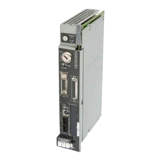
Overview Identifying the Processor’s Front These pictures show the Enhanced PLC-5 processor front panel components. Panel Components PLC-5/20E Processor Front Panel battery indicator (red when the battery is low) processor RUN/FAULT indicator (green when running; red when faulted) force indicator (amber when I/O forces are enabled) keyswitch;... - Page 9 Overview PLC-5/20E Processor Front Panel battery indicator (red when the battery is low) processor RUN/FAULT indicator (green when running; red when faulted) force indicator (amber when I/O forces are enabled) channel 0 communication status indicator (green when the channel is communicating) keyswitch;...
-
Page 10: Components You Need
Voltage, by applying the safety requirements of EN 61131-2 Programmable Controllers, Part 2 – Equipment Requirements and Tests. For specific information required by EN 61131-2, see the appropriate sections in this publication, as well as the following Allen-Bradley publications: • Industrial Automation Wiring and Grounding Guidelines For Noise Immunity, publication 1770-4.1... - Page 11 Chapter Set up the Hardware Install the hardware Install the hardware PC with (page 2-2) (page 2-2) Programming Software Connect the programming terminal Connect the programming terminal and the PLC-5 processor to the and the PLC-5 processor to the communication card communication card (page 2-6) (page 2-6)
-
Page 12: Install The Hardware
Set up the Hardware Install the Hardware Configure the I/O Chassis Set the backplane switches. Pressed in at top ON (closed) Switch Pressed in Last State at bottom OFF (open) Outputs of this I/O chassis remain in their last state when a hardware failure occurs. -
Page 13: Ground The I/O Chassis
Conductor Ground To Grounding Electrode System Ground Lug Nut and Captive Washer Star Washer Ground Lug I/O Chassis Wall 20626-M For more information, see the Allen-Bradley Programmable Controller Wiring and Grounding Guidelines, publication number 1770-4.1. Publication 1785-10.5 - November 1998... -
Page 14: Install The Power Supply
Set up the Hardware Install the Power Supply Set the jumpers on the back side of the power supply like this: Locking Connect the power cord to the 120V ac connector of the power supply module. This side plugs into connector on the module. insert wire insert wire here... -
Page 15: Install The Plc-5 Processor
For detailed information about handling and disposing More right of the Ethernet configuration jumper and shows the of the battery as well as other important guidelines, see hardware Ethernet address assigned by Allen-Bradley. publication AG-5.4. Publication 1785-10.5 - November 1998... -
Page 16: Power Up The System
Connect the Personal For more information, see: Computer to the • Enhanced and Ethernet PLC-5 Programmable Controller User PLC-5 Processor Manual, publication number 1785-6.5.12 • the documentation provided with your communication card •... -
Page 17: Install The Software And Set Up The Programming System
Chapter Set up the Software Install the software Start the programming software Powerup the system The following instructions are general. For specific information, see the documentation set for your particular software package. Install the Software and Set Before you install your programming software, make certain you meet the system requirements for that software –... -
Page 18: Power Up The System
Set up the Software Power Up the System Power up the system if you have not done so already. Check the LED display on the processor. If your system is operating properly, the PROC LED should be steady red and the message “Processor RAM should appear on is faulted. -
Page 19: Use The Plc-5 Processor
Chapter Troubleshoot the Processor System Use the PLC-5 Processor BATT Status Indicators (page 4-1) PROC FORCE COMM Use the PLC-5 Processor Troubleshoot General Problems Status Indicators Indicator Color Description Probable Cause Recommended Action BATT Battery low Battery low Replace battery within 10 days Battery is good Normal operation No action required... -
Page 20: Troubleshoot The Processor Communication Channels
Troubleshoot the Processor System Indicator Color Description Probable Cause Recommended Action FORCE Amber SFC and/or I/O forces Normal operation No action required (steady) enabled Amber SFC and/or I/O forces (blinking) present but not enabled SFC and/or I/O forces not present COMM No transmission on Normal operation if... -
Page 21: Troubleshoot The Ethernet Status Indicators
Processor requires Contact Allen-Bradley internal repair Global Technical Support (GTS) Blinking red Hardware or software fault Fault-code dependent Contact Allen-Bradley GTS (detected and reported via a ENET code) STAT Ethernet interface is functioning Normal operation Attach the processor to an... -
Page 22: General
Appendix Specifications General This table lists general specifications. 3.6A Backplane Current 65.00 BTU/hr Heat Dissipation Operating Temperature..0 to 60° C (32-140° F) Environmental Conditions Storage Temperature ..–40 to 85° C (–40 to 185° F) Relative Humidity . -
Page 23: Processor Specifications
• CSA Class I, Division 2, Groups A, B, C, D Agency Certification • UL listed (when product is marked) • CE marked for all applicable directives Processor Specifications This table lists specifications of each Ethernet PLC-5 family processor. Maximum Maximum Processor/ Maximum I/O... -
Page 24: Battery Specification
Specifications Battery Specification Battery Type Ethernet PLC-5 processors use 1770-XYC batteries which contain 0.65 grams of lithium. Average Battery Lifetime Specifications Worst-case Battery Life Estimates Battery Duration Battery used in this processor: At this temperature: Power off 100%: Power off 50%:... - Page 25 CSA-certified Allen-Bradley industrial control products. produits industriels de contrôle Allen-Bradley certifiés par la CSA. • This equipment is suitable for use in Class I, Division 2, • Cet équipement convient à l’utilisation dans des emplacements de Groups A, B, C, D, or non-hazardous locations only.
- Page 26 What is not in the right order? Other Comments Use back for more comments. Your Name Location/Phone Return to: Marketing Communications, Allen-Bradley Co., 1 Allen-Bradley Drive, Mayfield Hts., OH 44124-6118Phone: (440)646-3166 FAX: (440)646-4320 Publication ICCG-5.21 - August 1995 PN 955107-82...
- Page 27 PLEASE FASTEN HERE (DO NOT STAPLE) Other Comments PLEASE FOLD HERE NO POSTAGE NECESSARY IF MAILED IN THE UNITED STATES BUSINESS REPLY MAIL FIRST-CLASS MAIL PERMIT NO. 18235 CLEVELAND OH POSTAGE WILL BE PAID BY THE ADDRESSEE 1 ALLEN BRADLEY DR MAYFIELD HEIGHTS OH 44124-9705...
- Page 29 Publication 1785-10.5 - November 1998 PN 955133-86 © 1998 Rockwell International Corp. All Rights Reserved. Printed in USA Supersedes Publication 1785-10.5 - December1996...
Need help?
Do you have a question about the Ethernet PLC-5 and is the answer not in the manual?
Questions and answers