YASKAWA U1000 iQpump MATRIX Drive User Manual
Low harmonic regenerative pump controller
Hide thumbs
Also See for U1000 iQpump MATRIX Drive:
- Quick start manual (118 pages) ,
- Technical manual (706 pages) ,
- Quick start quide (26 pages)
Table of Contents
Advertisement
Quick Links
Download this manual
See also:
Technical Manual
Low Harmonic Regenerative Pump Controller
U1000 iQpump MATRIX Drive
User Manual
Type: CIMR-UW
Models: 200 V Class: 10 to 100 HP ND
400 V Class: 7.5 to 350 HP ND
To properly use the product, read this manual thoroughly and retain
for easy reference, inspection, and maintenance. Ensure the end user
receives this manual.
MANUAL NO. TOEPYAIUPW01A
PUBLISHED FEBRUARY 2017
REVISION: <0>
DRIVE SOFTWARE PRG: 0030
1
3
Receiving
4
2
Mechanical Installation
3
Electrical Installation
5
Start-Up Programming &
4
Operation
6
5
Troubleshooting
7
6
Periodic Inspection &
Maintenance
8
7
Peripheral Devices &
Options
A
A
Specifications
B
B
Parameter List
C
C
MEMOBUS/Modbus
D
Communications
D
E
Standards Compliance
Advertisement
Chapters
Table of Contents

Related Manuals for YASKAWA U1000 iQpump MATRIX Drive


Summary of Contents for YASKAWA U1000 iQpump MATRIX Drive
- Page 1 Low Harmonic Regenerative Pump Controller U1000 iQpump MATRIX Drive User Manual Type: CIMR-UW Models: 200 V Class: 10 to 100 HP ND 400 V Class: 7.5 to 350 HP ND To properly use the product, read this manual thoroughly and retain for easy reference, inspection, and maintenance.
- Page 2 Every precaution has been taken in the preparation of this manual. Yaskawa assumes no responsibility for errors or omissions. Neither is any liability assumed for damages resulting from the use of the information contained in this publication.
-
Page 3: Table Of Contents
Instructions on Installation Using the Eye Bolts and Hanging Brackets ........39 HOA Keypad Remote Usage ....................41 Exterior and Mounting Dimensions ..................44 3. ELECTRICAL INSTALLATION ..............49 3.1 Section Safety......................50 YASKAWA TOEPYAIUPW01A YASKAWA AC Drive - U1000 iQpump Matrix Drive User Manual... - Page 4 Changing Parameter Settings or Values ................... 99 4.5 Pump Application Presets ....................101 Modified Parameters Depending on A1-03 Setting ................. 101 Pump Quick Setup Menu Depending on A1-06 Setting ..............103 YASKAWA TOEPYAIUPW01A YASKAWA AC Drive - U1000 iQpump Matrix Drive User Manual...
- Page 5 5.8 HOA Keypad Display Messages ..................221 Fault Reset Methods ........................222 5.9 Auto-Tuning ........................223 Types of Auto-Tuning ........................223 Auto-Tuning Interruption and Fault Codes ..................224 Auto-Tuning Operation Example ..................... 224 YASKAWA TOEPYAIUPW01A YASKAWA AC Drive - U1000 iQpump Matrix Drive User Manual...
- Page 6 Drive Models 4o0011 to 4o0414 ....................270 A.4 Drive Derating Data ......................271 Rated Current Depending on Carrier Frequency ................271 Carrier Frequency Derating......................272 Temperature Derating ........................272 Altitude Derating..........................273 YASKAWA TOEPYAIUPW01A YASKAWA AC Drive - U1000 iQpump Matrix Drive User Manual...
- Page 7 L2: Momentary Power Loss Ride-Thru.................... 314 L3: Stall Prevention ......................... 315 L4: Speed Detection........................316 L5: Fault Restart..........................317 L6: Torque Detection........................318 L7: Torque Limit ..........................319 YASKAWA TOEPYAIUPW01A YASKAWA AC Drive - U1000 iQpump Matrix Drive User Manual...
- Page 8 B.18 V/f Pattern Default Values....................365 B.19 Defaults by Drive Model ....................366 C. MEMOBUS/MODBUS COMMUNICATIONS............371 C.1 MEMOBUS/Modbus Configuration ..................372 C.2 Communication Specifications ..................373 C.3 Connecting to a Network ....................374 YASKAWA TOEPYAIUPW01A YASKAWA AC Drive - U1000 iQpump Matrix Drive User Manual...
- Page 9 Slave Not Responding........................406 C.12 Self-Diagnostics ........................407 D. STANDARDS COMPLIANCE ................409 D.1 Section Safety........................410 D.2 UL Standards ........................412 UL Standards Compliance ......................412 Drive Motor Overload Protection ..................... 420 YASKAWA TOEPYAIUPW01A YASKAWA AC Drive - U1000 iQpump Matrix Drive User Manual...
- Page 10 Table of Contents This Page Intentionally Blank YASKAWA TOEPYAIUPW01A YASKAWA AC Drive - U1000 iQpump Matrix Drive User Manual...
- Page 11 Preface & General Safety This section provides safety messages pertinent to this product that, if not heeded, may result in fatality, personal injury, or equipment damage. Yaskawa is not responsible for the consequences of ignoring these instructions. PREFACE.......................12 GENERAL SAFETY....................13...
-
Page 12: I.1 Preface
Yaskawa must be supplied to the end user with appropriate warnings and instructions as to the safe use and operation of that part. Any warnings provided by Yaskawa must be promptly provided to the end user. -
Page 13: I.2 General Safety
• When ordering a new copy of the manual due to damage or loss, contact your Yaskawa representative or the nearest Yaskawa sales office and provide the manual number shown on the front cover. -
Page 14: Safety Messages
Do not attempt to modify or alter the drive in any way not explained in this manual. Failure to comply could result in death or serious injury. Yaskawa is not responsible for any modification of the product made by the user. This product must not be modified. Do not allow unqualified personnel to use equipment. - Page 15 Failure to comply may cause damage to the electrical components in the drive. Do not pack the drive in wooden materials that have been fumigated or sterilized. Do not sterilize the entire package after the product is packed. YASKAWA TOEPYAIUPW01A YASKAWA AC Drive - U1000 iQpump Matrix Drive User Manual...
-
Page 16: General Application Precautions
Grounding the Power Supply Yaskawa recommends using a dedicated ground for the power supply, as the drive is designed to run with a 1:1 ratio relative to the power supply. Ground other devices as directed in the specifications for those devices. Take particular care when connecting sensitive electronic devices. - Page 17 Yaskawa offers protective designs for drives that must be used in areas subjected to oil mist and excessive vibration. Contact Yaskawa or your Yaskawa agent for details.
-
Page 18: Motor Application Precautions
Figure i.1 shows the allowable load characteristics for a Yaskawa standard motor. Use a motor designed specifically for operation with a drive when 100% continuous torque is needed at low speeds. 25% ED (or 15 min) - Page 19 Contact Yaskawa or a Yaskawa agent when planning to use a motor that does not fall within these specifications: • Contact Yaskawa or a Yaskawa agent for questions concerning applications with larger inertia.
-
Page 20: Drive Label Warning Example
Customers who intend to use the product described in this manual for devices or systems relating to transportation, health care, space aviation, atomic power, electric power, or in underwater applications must first contact their Yaskawa representatives or the nearest Yaskawa sales office. -
Page 21: Receiving
This chapter explains how to inspect the drive upon receipt, and gives an overview of the different enclosure types and components. SECTION SAFETY....................22 GENERAL DESCRIPTION..................23 MODEL NUMBER AND NAMEPLATE CHECK............25 DRIVE MODELS AND ENCLOSURES..............28 COMPONENT NAMES...................29 YASKAWA TOEPYAIUPW01A YASKAWA AC Drive - U1000 iQpump Matrix Drive User Manual... -
Page 22: Section Safety
Ensure that the motor is suitable for drive duty and/or the motor service factor is adequate to accommodate the additional heating with the intended operating conditions. YASKAWA TOEPYAIUPW01A YASKAWA AC Drive - U1000 iQpump Matrix Drive User Manual... -
Page 23: General Description
2o0192 4o0077 2o0248 4o0096 – – 4o0124 – – 4o0156 – – 4o0180 – – 4o0216 – – 4o0240 – – 4o0302 – – 4o0361 – – 4o0414 YASKAWA TOEPYAIUPW01A YASKAWA AC Drive - U1000 iQpump Matrix Drive User Manual... -
Page 24: Control Mode Selection
When the output frequency matches the power supply frequency (60 Hz), the Commercial Power – PWM switching operation stops and Switching Selection switches to operation with a direct commercial power supply connection. YASKAWA TOEPYAIUPW01A YASKAWA AC Drive - U1000 iQpump Matrix Drive User Manual... -
Page 25: Model Number And Nameplate Check
E – Serial number Figure 1.1 Drive Nameplate Information Example <1> The address of the head office of Yaskawa Electric Corporation (responsible for product liability) is shown on the nameplate. YASKAWA TOEPYAIUPW01A YASKAWA AC Drive - U1000 iQpump Matrix Drive User Manual... - Page 26 22 (30) 4o0052 30 (40) 4o0065 37 (50) 4o0077 45 (60) 4o0096 55 (75) 4o0124 75 (100) 4o0156 90 (125) 110 (150) 4o0180 4o0216 132 (175) 4o0240 150 (200) YASKAWA TOEPYAIUPW01A YASKAWA AC Drive - U1000 iQpump Matrix Drive User Manual...
- Page 27 1.3 Model Number and Nameplate Check Drive Model Reference Motor Capacity kW (HP) Rated Output Current A 4o0302 185 (250) 4o0361 220 (300) 4o0414 260 (350) YASKAWA TOEPYAIUPW01A YASKAWA AC Drive - U1000 iQpump Matrix Drive User Manual...
-
Page 28: Drive Models And Enclosures
1.4 Drive Models and Enclosures Drive Models and Enclosures Yaskawa offers IP00/Open Type enclosures for the U1000 iQpump. IP00/Open Type models are designed for installation in an enclosure panel that serves to protect personnel from injury caused by accidentally touching live parts. -
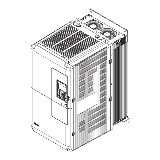
Page 29: Component Names
A – Cooling fan D – Digital operator B – Heatsink E – Front cover C – Terminal cover F – Eye bolt Figure 1.3 IP00/Open Type Components (Drive Model 2o0028A) YASKAWA TOEPYAIUPW01A YASKAWA AC Drive - U1000 iQpump Matrix Drive User Manual... - Page 30 A – Cooling fan D – Digital operator B – Heatsink E – Front cover C – Terminal cover F – Eye bolt Figure 1.4 IP00/Open Type Components (Drive Model 2o0104A) YASKAWA TOEPYAIUPW01A YASKAWA AC Drive - U1000 iQpump Matrix Drive User Manual...
- Page 31 E – Front cover B – Heatsink F – Drive cover C – Terminal cover G – Hanging bracket D – Digital operator Figure 1.5 IP00/Open Type Components (Drive Model 2o0154A) YASKAWA TOEPYAIUPW01A YASKAWA AC Drive - U1000 iQpump Matrix Drive User Manual...
- Page 32 F – Drive cover 2 C – Terminal cover G – Drive cover 1 D – Digital operator H – Hanging bracket Figure 1.6 IP00/Open Type Components (Drive Model 2o0248A) YASKAWA TOEPYAIUPW01A YASKAWA AC Drive - U1000 iQpump Matrix Drive User Manual...
-
Page 33: Front Views
A – Terminal board (Refer to Control B – Main circuit terminal (Refer to Circuit Wiring on page Wiring the Main Circuit Terminal on page Figure 1.7 Front Views of Drives YASKAWA TOEPYAIUPW01A YASKAWA AC Drive - U1000 iQpump Matrix Drive User Manual... - Page 34 1.5 Component Names This Page Intentionally Blank YASKAWA TOEPYAIUPW01A YASKAWA AC Drive - U1000 iQpump Matrix Drive User Manual...
-
Page 35: Mechanical Installation
Mechanical Installation This chapter explains how to properly mount and install the drive. SECTION SAFETY....................36 MECHANICAL INSTALLATION................38 YASKAWA TOEPYAIUPW01A YASKAWA AC Drive - U1000 iQpump Matrix Drive User Manual... -
Page 36: Section Safety
If the motor is to be operated at a speed higher than the rated speed, consult with the manufacturer. Continuously operating an oil-lubricated motor in the low-speed range may result in burning. YASKAWA TOEPYAIUPW01A YASKAWA AC Drive - U1000 iQpump Matrix Drive User Manual... - Page 37 This is also applicable when an existing explosion-proof motor is to be operated with the drive. Since the drive itself is not explosion-proof, always install it in a safe place. Never lift the drive up while the cover is removed. This can damage the terminal board and other components. YASKAWA TOEPYAIUPW01A YASKAWA AC Drive - U1000 iQpump Matrix Drive User Manual...
-
Page 38: Mechanical Installation
2.1. Failure to comply may damage the drive due to improper cooling. Figure 2.1 Correct Installation Orientation NOTICE: Install the drive upright as specified in the manual. Failure to comply may damage the drive due to improper cooling. YASKAWA TOEPYAIUPW01A YASKAWA AC Drive - U1000 iQpump Matrix Drive User Manual... -
Page 39: Instructions On Installation Using The Eye Bolts And Hanging Brackets
To make a wire hanger or frame for use when lifting the drive with a crane, lay the drive in a horizontal position and pass a wire through the hanging brackets. YASKAWA TOEPYAIUPW01A YASKAWA AC Drive - U1000 iQpump Matrix Drive User Manual... - Page 40 3. Lower the drive when ready to install in the enclosure panel. Stop lowering when near the floor, then slowly begin lowering the drive or again until the drive is placed correctly. YASKAWA TOEPYAIUPW01A YASKAWA AC Drive - U1000 iQpump Matrix Drive User Manual...
-
Page 41: Hoa Keypad Remote Usage
The HOA keypad can also be permanently mounted remote locations such as panel doors using an extension cable and an installation support set (depending on the installation type). Note: Refer to Peripheral Devices & Options on page 251 for information on extension cables and installation support sets. YASKAWA TOEPYAIUPW01A YASKAWA AC Drive - U1000 iQpump Matrix Drive User Manual... - Page 42 Failure to comply could result in damage to the drive. Place a temporary cover over the top of the drive during installation. Remove the temporary cover before drive start-up, as the cover will reduce ventilation and cause the drive to overheat. YASKAWA TOEPYAIUPW01A YASKAWA AC Drive - U1000 iQpump Matrix Drive User Manual...
- Page 43 Enclosure panel Figure 2.11 External/Face-Mount Installation Internal/Flush-Mount An internal/flush-mount requires an installation support set that must be purchased separately. Contact Yaskawa to order an installation support set and mounting hardware. Figure 2.12 illustrates how to attach the Installation Support Set A.
-
Page 44: Exterior And Mounting Dimensions
<1> Attach a top protective cover and bottom cover from the optional End Cap Kit to an IP00/Open Type enclosure drive to convert the drive to an IP20/NEMA 1, UL Type 1 enclosure drive. YASKAWA TOEPYAIUPW01A YASKAWA AC Drive - U1000 iQpump Matrix Drive User Manual... - Page 45 (15.86) (9.84) (38.03) (0.43) (1.58) (6.49) (0.18) (0.15) (0.47) (245) 2o0192A 1132 1104 14.5 2o0248A (19.29) (44.56) (17.71) (14.17) (7.08) (43.46) (0.57) (1.92) (7.12) (0.18) (0.18) (0.55) (388) YASKAWA TOEPYAIUPW01A YASKAWA AC Drive - U1000 iQpump Matrix Drive User Manual...
- Page 46 IP20/NEMA 1, UL Type 1 Kit when performing the conversion. Contact a Yaskawa representative for IP20/NEMA 1, UL Type 1 Kit availability for IP00/Open Type models not listed. Table 2.6 IP20/NEMA 1, UL Type 1 Kit Selection (240 V 3-Phase)
- Page 47 Figure 1 Figure 2 Max 15 mm Max 15 mm Max 15 mm Max 15 mm (0.60 in) (0.60 in) (0.60 in) (0.60 in) Figure 4 Figure 3 YASKAWA TOEPYAIUPW01A YASKAWA AC Drive - U1000 iQpump Matrix Drive User Manual...
- Page 48 (7.12) (0.18) (0.18) (0.55) (398) 4o0240 4o0302 1460 1132 1102 14.5 4o0361 (27.36) (57.48) (17.71) (22.05) (11.02) (44.56) (43.39) (0.57) (11.81) (1.14) (7.00) (0.18) (0.18) (0.55) (595) 4o0414 YASKAWA TOEPYAIUPW01A YASKAWA AC Drive - U1000 iQpump Matrix Drive User Manual...
-
Page 49: Electrical Installation
TERMINAL COVER....................59 HOA KEYPAD AND FRONT COVER..............62 TOP PROTECTIVE COVER...................65 MAIN CIRCUIT WIRING..................66 CONTROL CIRCUIT WIRING................73 3.10 CONTROL I/O CONNECTIONS................79 3.11 CONNECT TO A PC....................85 3.12 WIRING CHECKLIST.....................86 YASKAWA TOEPYAIUPW01A YASKAWA AC Drive - U1000 iQpump Matrix Drive User Manual... -
Page 50: Section Safety
Loose electrical connections could result in death or serious injury by fire due to overheating of electrical connections. Failure to comply could result in death or serious injury by fire. Attach the drive to metal or other noncombustible material. YASKAWA TOEPYAIUPW01A YASKAWA AC Drive - U1000 iQpump Matrix Drive User Manual... - Page 51 Failure to comply may damage the drive and will void warranty. Yaskawa is not responsible for any modification of the product made by the user. This product must not be modified. Check all the wiring to ensure that all connections are correct after installing the drive and connecting any other devices.
-
Page 52: Standard Connection Diagram
NOTICE: Do not connect more than one multi-function input to one terminal. Improper wiring may result in drive malfunction. Use an external power supply when sharing a terminal with more than one input. Do not use the built-in +24 V power supply. YASKAWA TOEPYAIUPW01A YASKAWA AC Drive - U1000 iQpump Matrix Drive User Manual... - Page 53 +24 Vdc Transducer Supply - (maximum 150 mA) twisted-pair shielded line control circuit terminal main circuit terminal shielded line Figure 3.1 Drive Standard Connection Diagram (Example: Model 2o0028) YASKAWA TOEPYAIUPW01A YASKAWA AC Drive - U1000 iQpump Matrix Drive User Manual...
- Page 54 <8> Use jumper S5 to select between voltage or current output signals at terminals AM and FM. Set parameters H4-07 and H4-08 accordingly. <9> Monitor outputs work with devices such as analog frequency meters, ammeters, voltmeters, and wattmeters. They are not intended for use as a feedback-type signal. YASKAWA TOEPYAIUPW01A YASKAWA AC Drive - U1000 iQpump Matrix Drive User Manual...
-
Page 55: Main Circuit Connection Diagram
Figure 3.2 Connecting Main Circuit Terminals <1> A Momentary Power Loss Recovery Unit can be connected as an option. Do not connect an AC power supply to these terminals. YASKAWA TOEPYAIUPW01A YASKAWA AC Drive - U1000 iQpump Matrix Drive User Manual... -
Page 56: Terminal Block Configuration
Figure 3.7 4o0240 4o0302 4o0361 Figure 3.8 4o0414 CHARGE R/L1 S/L2 T/L3 U/T1 V/T2 W/T3 Figure 3.3 Main Circuit Terminal Configuration (Drive Models 2o0028 and 4o0011 to 4o0034) YASKAWA TOEPYAIUPW01A YASKAWA AC Drive - U1000 iQpump Matrix Drive User Manual... - Page 57 Figure 3.4 Main Circuit Terminal Configuration (Drive Models 2o0042 to 2o0081 and 4o0040 to 4o0077) n1 p1 R/L1 S/L2 T/L3 U/T1 V/T2 W/T3 Figure 3.5 Main Circuit Terminal Configuration (Drive Models 2o0104, 2o0130, 4o0096, and 4o0124) YASKAWA TOEPYAIUPW01A YASKAWA AC Drive - U1000 iQpump Matrix Drive User Manual...
- Page 58 Figure 3.7 Main Circuit Terminal Configuration (Drive Models 2o0248, 4o0216, and 4o0240) n1 p1 R/L1 S/L2 T/L3 U/T1 V/T2 W/T3 Figure 3.8 Main Circuit Terminal Configuration (Drive Models 4o0302 to 4o0414) YASKAWA TOEPYAIUPW01A YASKAWA AC Drive - U1000 iQpump Matrix Drive User Manual...
-
Page 59: Terminal Cover
Push in on the tab located on the bottom of the terminal cover and gently pull forward to remove the terminal cover. Figure 3.10 Removing the Terminal Cover YASKAWA TOEPYAIUPW01A YASKAWA AC Drive - U1000 iQpump Matrix Drive User Manual... -
Page 60: Models 2O0154 To 2O0248 And 4O0156 To 4O0414
Figure 3.12 Removing the Terminal Cover Pull forward on the terminal cover to free it from the drive. Figure 3.13 Removing the Terminal Cover YASKAWA TOEPYAIUPW01A YASKAWA AC Drive - U1000 iQpump Matrix Drive User Manual... - Page 61 <1> Figure 3.14 Reattaching the Terminal Cover <1> Connect the ground wiring first, then the main circuit wiring, and finally the control circuit wiring. YASKAWA TOEPYAIUPW01A YASKAWA AC Drive - U1000 iQpump Matrix Drive User Manual...
-
Page 62: Hoa Keypad And
Figure 3.17 Remove the Front Cover (Drive Models 2o0028 to 2o0130 and 4o0011 to 4o0124) o 0154 to 2 o 0248 and 4 o 0156 to 4 o 0414 Drive Models 2 YASKAWA TOEPYAIUPW01A YASKAWA AC Drive - U1000 iQpump Matrix Drive User Manual... - Page 63 Unhook the left side of the front cover then swing the left side towards you as shown in Figure 3.19 until the cover comes off. Figure 3.19 Remove the Front Cover (Drive Models 2o0154 to 2o0248 and 4o0156 to 4o0414) YASKAWA TOEPYAIUPW01A YASKAWA AC Drive - U1000 iQpump Matrix Drive User Manual...
- Page 64 Figure 3.20 Reattach the Front Cover (Drive Models 2o0154 to 2o0248 and 4o0156 to 4o0414) After connecting the hooks to the drive, press firmly on the cover to lock it into place. YASKAWA TOEPYAIUPW01A YASKAWA AC Drive - U1000 iQpump Matrix Drive User Manual...
-
Page 65: Top Protective Cover
Removing the top protective cover from an IP20/UL Type 1 enclosure drive voids UL Type 1 protection while retaining IP20 conformity. Figure 3.22 Removing the Top Protective Cover YASKAWA TOEPYAIUPW01A YASKAWA AC Drive - U1000 iQpump Matrix Drive User Manual... -
Page 66: Main Circuit Wiring
Figure 3.23 Main Circuit Protective Cover (Drive Models 2o0028 to 2o0081 and 4o0011 to 4o0077) Attach the protective covers after wiring the main circuit terminals and p1, and n1 terminals on drive models 2o0104 to 2o0248 and 4o0096 to 4o0414. YASKAWA TOEPYAIUPW01A YASKAWA AC Drive - U1000 iQpump Matrix Drive User Manual... -
Page 67: Main Circuit Wire Gauges And Tightening Torque
Line drop voltage (V) = 3 × wire resistance (Ω/km) × wire length (m) × current (A) × 10 Refer to UL Standards Compliance on page 412 for information on UL compliance. The wire gauges listed in the following tables are Yaskawa recommendations. Refer to local codes for proper wire gauge selections. Three-Phase 200 V Class Drives Table 3.3 Drive Wire Gauge and Torque Specifications (Three-Phase 200 V Class) - Page 68 (3 to 2/0) (156 to 200) 2.5 to 4 2.5 to 4 1.2 to 2.0 p1, n1 (14) (14 to 12) (14) (14 to 12) (10.4 to 17.4) YASKAWA TOEPYAIUPW01A YASKAWA AC Drive - U1000 iQpump Matrix Drive User Manual...
- Page 69 (10 to 5) (34.7 to 43.4) 2.5 to 4 2.5 to 4 1 to 1.4 p1, n1 (14) (14 to 12) (14) (14 to 12) (8.9 to 12.4) YASKAWA TOEPYAIUPW01A YASKAWA AC Drive - U1000 iQpump Matrix Drive User Manual...
- Page 70 (3 to 2/0) (156 to 200) 2.5 to 4 2.5 to 4 1.2 to 2.0 p1, n1 (14) (14 to 12) (14) (14 to 12) (10.4 to 17.4) YASKAWA TOEPYAIUPW01A YASKAWA AC Drive - U1000 iQpump Matrix Drive User Manual...
-
Page 71: Main Circuit Terminal And Motor Wiring
NOTICE: Route motor leads U/T1, V/T2, and W/T3 separate from all other leads to reduce possible interference related issues. Failure to comply may result in abnormal operation of drive and nearby equipment. YASKAWA TOEPYAIUPW01A YASKAWA AC Drive - U1000 iQpump Matrix Drive User Manual... - Page 72 Drive Models 2o0028 to 2o0081 and 4o0011 to 4o0077 have a cover placed over terminals p1 and n1 prior to shipment to help prevent miswiring. Use wire cutters to cut away covers as needed for terminals. YASKAWA TOEPYAIUPW01A YASKAWA AC Drive - U1000 iQpump Matrix Drive User Manual...
-
Page 73: Control Circuit Wiring
S1 S2 S3 S4 S5 S6 S7 S8 SN SC SP S1 S2 S3 S4 S5 S6 S7 S8 SN SC SP MA MB MC Figure 3.26 Control Circuit Terminal Arrangement YASKAWA TOEPYAIUPW01A YASKAWA AC Drive - U1000 iQpump Matrix Drive User Manual... - Page 74 (HAND frequency reference) • Voltage or current input must be selected by jumper S1 and H3-05. Frequency reference common E (G) Ground for shielded lines and option cards – – YASKAWA TOEPYAIUPW01A YASKAWA AC Drive - U1000 iQpump Matrix Drive User Manual...
- Page 75 0.75 (18) 0.5 (20) (4.4 to 5.3) Solid wire: (24 to 20) etc. 0.2 to 1.5 M1-M4 (24 to 16) FM, AM, AC R+, R-, S+, S-, IG YASKAWA TOEPYAIUPW01A YASKAWA AC Drive - U1000 iQpump Matrix Drive User Manual...
-
Page 76: Wiring The Control Circuit Terminal
3.9 Control Circuit Wiring Ferrule-Type Wire Terminals Yaskawa recommends using CRIMPFOX 6, a crimping tool manufactured by PHOENIX CONTACT, to prepare wire ends with insulated sleeves before connecting to the drive. See Table 3.10 for dimensions. Figure 3.27 Ferrule Dimensions Table 3.10 Ferrule Terminal Types and Sizes... - Page 77 NOTICE: The analog signal wiring between the drive and the operator station or peripheral equipment should not exceed 50 meters when using an analog signal from a remote source to supply the frequency reference. Failure to comply could result in poor system performance. YASKAWA TOEPYAIUPW01A YASKAWA AC Drive - U1000 iQpump Matrix Drive User Manual...
-
Page 78: Switches And Jumpers On The Terminal Board
S1 S2 S3 S4 S5 S6 S7 S8 SN SC SP MA MB MC Selection A1 A2 A3 Figure 3.31 Locations of Jumpers and Switches on the Terminal Board YASKAWA TOEPYAIUPW01A YASKAWA AC Drive - U1000 iQpump Matrix Drive User Manual... -
Page 79: Control I/O Connections
External 24 Vdc Power Supply (Terminals SN and SP) Sinking Mode (NPN) 24 Vdc 24 Vdc External 24 Vdc ±10% Sourcing Mode (PNP) 24 Vdc 24 Vdc External 24 Vdc ±10% YASKAWA TOEPYAIUPW01A YASKAWA AC Drive - U1000 iQpump Matrix Drive User Manual... -
Page 80: Terminals A1, A2, And A3 Input Signal Selection
0: 0 to 10 Vdc H3-09 Terminal A2 signal level selection 1: 0 to 10 Vdc Bipolar 0 to 3 2: 4 to 20 mA 3: 0 to 20 mA YASKAWA TOEPYAIUPW01A YASKAWA AC Drive - U1000 iQpump Matrix Drive User Manual... - Page 81 Block Block 24V Power Supply 24V Power Supply Transducer Supply Common Signal 4-20 mA Transducer (typical) Signal 0-10 Vdc (typical) Output Shield Shield E(G) E(G) Output YASKAWA TOEPYAIUPW01A YASKAWA AC Drive - U1000 iQpump Matrix Drive User Manual...
- Page 82 A1 A2 A3 Set jumper S1 to the “I” position for the last iQpump drive on the network. All other iQpump drives should have S1 set to the “V” position. YASKAWA TOEPYAIUPW01A YASKAWA AC Drive - U1000 iQpump Matrix Drive User Manual...
-
Page 83: Terminal Am/Fm Signal Selection
0: 0 to 10 Vdc H3-09 Terminal A2 Signal Level Selection 1: -10 to 10 Vdc 0 to 3 2: 4 to 20 mA 3: 0 to 20 mA YASKAWA TOEPYAIUPW01A YASKAWA AC Drive - U1000 iQpump Matrix Drive User Manual... -
Page 84: Terminal A3 Analog/Ptc Input Selection
Description AI (lower position) (default) Analog input for the function selected in parameter H3-06 PTC (upper position) PTC input. Parameter H3-06 must be set to E (PTC input) YASKAWA TOEPYAIUPW01A YASKAWA AC Drive - U1000 iQpump Matrix Drive User Manual... -
Page 85: Connect To A Pc
The drive can connect to a USB port on a PC using a USB 2.0, AB-type cable (sold separately). After connecting the drive to a PC, Yaskawa DriveWizard Industrial software can be used to monitor drive performance and manage parameter settings. -
Page 86: Wiring Checklist
Ensure that no frayed wires on the terminal block are touching other terminals or connections. – Properly separate control circuit wiring and main circuit wiring. – Analog signal line wiring should not exceed 50 m (164 ft.). – YASKAWA TOEPYAIUPW01A YASKAWA AC Drive - U1000 iQpump Matrix Drive User Manual... -
Page 87: Start-Up Programming & Operation
USING THE HOA KEYPAD..................94 PUMP APPLICATION PRESETS................101 U1000 IQPUMP PRESETS AND FUNCTIONS............104 BASIC U1000 IQPUMP SETUP AND APPLICATION PRESET PARAMETERS139 TEST RUN WITH NO LOAD................175 TEST RUN WITH LOAD CONNECTED...............176 YASKAWA TOEPYAIUPW01A YASKAWA AC Drive - U1000 iQpump Matrix Drive User Manual... -
Page 88: Drive Start-Up Preparation
The drive is thoroughly tested at the factory. The start up person should verify that the drive is free of shipping and installation damage. Shipping damage is not covered by the Yaskawa warranty. Claims must be filed with the shipping company as soon as possible for any potential recovery via insurance. - Page 89 Record any other connections to the drive to determine if special programming is required for the following: Multi-function Inputs Multi-function Outputs Multi-function Digital Inputs Multi-function Analog Outputs Network Communications YASKAWA TOEPYAIUPW01A YASKAWA AC Drive - U1000 iQpump Matrix Drive User Manual...
-
Page 90: Powering Up The Drive
Set in 24-hour clock time. After initial setup, the time will display in 12-hour clock time. Set the gain or loss in seconds per month. Second per month Note: This does not need to be set for the RTC to function properly. YASKAWA TOEPYAIUPW01A YASKAWA AC Drive - U1000 iQpump Matrix Drive User Manual... - Page 91 HOA operator that has not yet been set. Press F2 to Set DATA - MODE - Use the up and down arrow keys to scroll through display menu until the screen shows Programming “Programming”. HOME YASKAWA TOEPYAIUPW01A YASKAWA AC Drive - U1000 iQpump Matrix Drive User Manual...
- Page 92 Setting 2: Reset The Real-Time Clock data is cleared. A Clock Not Set alarm will occur until o4-17 is set to 1 and the Real-Time Clock is set. YASKAWA TOEPYAIUPW01A YASKAWA AC Drive - U1000 iQpump Matrix Drive User Manual...
-
Page 93: Application Selection
A1-06 Application Presets (monitor only) 8: Pressure Control 9: Pump Down Level 11: VTC Pressure Control 12: Pivot Panel VTC 13: Advanced Pressure Control 14: Pivot Panel Submersible YASKAWA TOEPYAIUPW01A YASKAWA AC Drive - U1000 iQpump Matrix Drive User Manual... -
Page 94: Using The Hoa Keypad
AUTO HAND Light Lit while the drive is in HAND mode. Refer to page for details. HAND ALM LED Light Refer to ALARM (ALM) LED Displays on page YASKAWA TOEPYAIUPW01A YASKAWA AC Drive - U1000 iQpump Matrix Drive User Manual... -
Page 95: Lcd Display
Function Key 2 → Pressing scrolls the cursor to the right. (F2) RESET Pressing resets the existing drive fault error. Monitor Pressing switches Monitor mode. YASKAWA TOEPYAIUPW01A YASKAWA AC Drive - U1000 iQpump Matrix Drive User Manual... -
Page 96: Alarm (Alm) Led Displays
HAND AUTO mode, Ready, No run command input. Short blink (15% duty) AUTO HAND AUTO mode, stopped by a Fast- Stop from a Multi-Function Digital Input. Double blink YASKAWA TOEPYAIUPW01A YASKAWA AC Drive - U1000 iQpump Matrix Drive User Manual... - Page 97 RUN Command 6 Hz 0 Hz Frequency AUTO LED Short blink Blink Blink HAND LED Operation Mode AUTO Figure 4.5 LEDs and Drive Operation in AUTO and HAND Modes YASKAWA TOEPYAIUPW01A YASKAWA AC Drive - U1000 iQpump Matrix Drive User Manual...
-
Page 98: Menu Structure For Hoa Keypad
<5> The Frequency Reference appears after the initial display that shows the product name. <6> The information that appears on the display will vary depending on the drive model. YASKAWA TOEPYAIUPW01A YASKAWA AC Drive - U1000 iQpump Matrix Drive User Manual... -
Page 99: Changing Parameter Settings Or Values
Entry Accepted -PRMSET- Decel Time 1 C1-02= 20.0sec 11. The display automatically returns to the screen shown in Step 6. (0.0~6000.0) “10.0 sec” Home DATA YASKAWA TOEPYAIUPW01A YASKAWA AC Drive - U1000 iQpump Matrix Drive User Manual... - Page 100 Display/Result - MODE - Auto Setpoint U5-99= 0.0PSI 12. Press as many times as necessary to return to the initial display. U1-02= 0.00Hz LSEQ U1-91= 0.0PSI LREF <-MONITOR-> YASKAWA TOEPYAIUPW01A YASKAWA AC Drive - U1000 iQpump Matrix Drive User Manual...
-
Page 101: Pump Application Presets
Q5-10 5.0 min Q5-11 Q5-16 1.00 Q5-17 3.0 s H2-01 H2-02 H2-03 P1-40 60.0 Hz P3-01 P3-04 5.0 PSI P3-06 5.0 Hz P3-07 7.0 s P3-10 2.0 PSI YASKAWA TOEPYAIUPW01A YASKAWA AC Drive - U1000 iQpump Matrix Drive User Manual... - Page 102 L5-04 180.0 s P2-03 15 s o1-06 P2-23 0.00% P1-05 0 sec P5-01 P1-06 0.0 Hz P5-02 6.0 Hz P4-12 0.0 Hz P4-17 0.0 min P5-02 0.0 Hz YASKAWA TOEPYAIUPW01A YASKAWA AC Drive - U1000 iQpump Matrix Drive User Manual...
-
Page 103: Pump Quick Setup Menu Depending On A1-06 Setting
P1-15 P1-12 P1-12 P4-01 P1-16 P4-01 P2-02 P4-02 L5-50 P4-02 P2-03 P4-03 P1-19 P4-03 P4-01 Q3-01 P1-20 Q3-01 P4-02 Q3-02 P1-23 Q3-02 P4-03 L5-51 Q3-01 P5-04 Q3-02 P4-10 YASKAWA TOEPYAIUPW01A YASKAWA AC Drive - U1000 iQpump Matrix Drive User Manual... -
Page 104: U1000 Iqpump Presets And Functions
By sleeping, the drive will save energy and mechanical wear. A setting of zero in P1-04 will disable the sleep function (default setting). YASKAWA TOEPYAIUPW01A YASKAWA AC Drive - U1000 iQpump Matrix Drive User Manual... - Page 105 PID Controller Setpoint 1 Minimum: 0.0 Maximum: 6000.0 U1-99 Anti-No-Flow Timer No signal output available <1> Range is 0.0 to 999.9 with sign-bit “-” indicating Delta to Setpoint. YASKAWA TOEPYAIUPW01A YASKAWA AC Drive - U1000 iQpump Matrix Drive User Manual...
-
Page 106: Suction Control Via Constant Pressure W/Well Draw Down
Set minimum suction pressure (Q5-04) – Sleep Level for Suction Control. Set suction pressure wake-up level (Q5-06) – Wake-up level. Set suction control minimum speed (Q5-08) – Minimum Flow Speed. YASKAWA TOEPYAIUPW01A YASKAWA AC Drive - U1000 iQpump Matrix Drive User Manual... -
Page 107: General Purpose Mode Application Preset
Acceleration Time 1 Maximum: 6000.0 <1> Default: 20.0 s C1-02 Deceleration Time 1 Minimum: 0.0 Maximum: 6000.0 Default: 60.0 Hz E1-04 Maximum Output Frequency Minimum: 40.0 Maximum: 400.0 YASKAWA TOEPYAIUPW01A YASKAWA AC Drive - U1000 iQpump Matrix Drive User Manual... - Page 108 Range: 0, 1 <1> Range is set by C1-10, Accel/Decel Time Setting Units. When C1-10 = 0 (units of 0.01 seconds), the setting range becomes 0.00 to 600.00 seconds. YASKAWA TOEPYAIUPW01A YASKAWA AC Drive - U1000 iQpump Matrix Drive User Manual...
-
Page 109: Well Draw Down Control Application Preset
4 to 20 mA input. Make sure to set all necessary parameters for proper constant pressure regulation. YASKAWA TOEPYAIUPW01A YASKAWA AC Drive - U1000 iQpump Matrix Drive User Manual... - Page 110 Pre-Charge Loss of Prime Level Minimum: 0.0 Maximum: 1000.0 Default: 0.0 Q1-01 PID Controller Setpoint 1 Minimum: 0.0 Maximum: 6000.0 Default: 0 Q4-01 Water Level Selection Range: 0, 1 YASKAWA TOEPYAIUPW01A YASKAWA AC Drive - U1000 iQpump Matrix Drive User Manual...
- Page 111 Default: 0 Q4-15 Low Water Level Detection Time Unit Range: 0, 1 U1-01 Frequency Reference 10 V: Maximum frequency Full scale: U1-97 Water Level 10 V = Q4-02 YASKAWA TOEPYAIUPW01A YASKAWA AC Drive - U1000 iQpump Matrix Drive User Manual...
-
Page 112: Low City Or Low Suction Inlet Pressure
• Check control wiring to drive terminal strip from pressure switch contact. to the pump. • Check to make sure that suction pressure is present by means of a separate measuring device. YASKAWA TOEPYAIUPW01A YASKAWA AC Drive - U1000 iQpump Matrix Drive User Manual... - Page 113 • Check control wiring to drive terminal strip from pressure switch contact. • Check to make sure that suction pressure is present by means of a separate measuring device. YASKAWA TOEPYAIUPW01A YASKAWA AC Drive - U1000 iQpump Matrix Drive User Manual...
-
Page 114: Water Level / Suction Pressure Control
Start / Draw Down Level Range: 0.0 to 999.9 Default: 0.0 P1-08 Low Feedback Level Range: 0.0 to 999.9 Default: 155.0 P1-11 High Feedback Level Range: 0.0 to 999.9 YASKAWA TOEPYAIUPW01A YASKAWA AC Drive - U1000 iQpump Matrix Drive User Manual... -
Page 115: Current Limit
• Reduce the load. Drive output speed is being limited due to • Verify setting of Q3-02. the output current limit. • Change to a larger drive size. YASKAWA TOEPYAIUPW01A YASKAWA AC Drive - U1000 iQpump Matrix Drive User Manual... -
Page 116: Vertical Turbine Controller (Vtc)
(P1-06) and the sleep level. It is important that all lag pumps be de-staged above the sleep level or the drive will not enter sleep mode YASKAWA TOEPYAIUPW01A YASKAWA AC Drive - U1000 iQpump Matrix Drive User Manual... - Page 117 Minimum: 1 Maximum: 5 Default: 2 s P3-05 Add Pump Delay Time Minimum: 0 Maximum: 3600 Default: 5 s P3-09 Shutdown Pump Delay Time Minimum: 0 Maximum: 3600 YASKAWA TOEPYAIUPW01A YASKAWA AC Drive - U1000 iQpump Matrix Drive User Manual...
- Page 118 Range: 0, 1 Default: 0.0 Q1-01 PID Controller Setpoint 1 Minimum: 0.0 Maximum: 6000.0 U1-91 Pump Feedback No signal output available U1-99 Anti-No-Flow Timer No signal output available YASKAWA TOEPYAIUPW01A YASKAWA AC Drive - U1000 iQpump Matrix Drive User Manual...
-
Page 119: Pre-Charge Function With One Lag Pump
Conditions for Exiting the Pre-Charge Mode • When Pre-Charge timer expires (P4-03). The drive will always exit after the pre-charge timer expires. YASKAWA TOEPYAIUPW01A YASKAWA AC Drive - U1000 iQpump Matrix Drive User Manual... - Page 120 (H 2-0x = A4) P4-01 Pre-cha rge level = 0.0 AND P4-07 Pre-cha rge T im e 2 = 0.0 m in Figure 4.8 Pre-Charge Single Speed Complete via Timer YASKAWA TOEPYAIUPW01A YASKAWA AC Drive - U1000 iQpump Matrix Drive User Manual...
- Page 121 PID Se lect = 1 (Enab led) AND b5-09 Ou tpu t Le vel Se l = 0 (N orm al C ha racter) Figure 4.10 Pre-Charge Complete via Normal PID Feedback YASKAWA TOEPYAIUPW01A YASKAWA AC Drive - U1000 iQpump Matrix Drive User Manual...
-
Page 122: Setpoint Boost After Lag Pump De-Staging
Minimum: -20.0 Maximum: 20.0 Default: 5.0 s P3-11 Setpoint Boost after De-stage Time Minimum: 0.0 Maximum: 60.0 Default: 0.0 Q1-01 PID Controller Setpoint 1 Minimum: 0.0 Maximum: 6000.0 YASKAWA TOEPYAIUPW01A YASKAWA AC Drive - U1000 iQpump Matrix Drive User Manual... -
Page 123: Frequency Reduction After Lag Pump Staging
Minimum: -20.0 Maximum: 20.0 Default: 5.0 s P3-11 Setpoint Boost after De-Stage Time Minimum: 0.0 Maximum: 60.0 Default: 0.0 Q1-01 PID Controller Setpoint 1 Minimum: 0.0 Maximum: 6000.0 YASKAWA TOEPYAIUPW01A YASKAWA AC Drive - U1000 iQpump Matrix Drive User Manual... -
Page 124: Using The Do-A3 Option For Additional Lag Pumps
(Contactor Multiplex) F5-07 = 83 PUMP 4 DO-A3 F5-09 = 2 F5-08 = 84 PUMP 5 LEAD PUMP 1 Figure 4.11 Controlling Five Lag Pumps with DO-A3 Option YASKAWA TOEPYAIUPW01A YASKAWA AC Drive - U1000 iQpump Matrix Drive User Manual... -
Page 125: De-Scale/De-Ragging
Range: 0.0 to 400.0 Default: 10 s P8-04 De-scale Forward Run Time Range: 1 to 6000 Default: 10 s P8-05 De-scale Reverse Run Time Range: 1 to 6000 YASKAWA TOEPYAIUPW01A YASKAWA AC Drive - U1000 iQpump Matrix Drive User Manual... - Page 126 Range: 0.1 to 2000.0 Default: 25.00 Hz p8-09 De-scale Reverse Frequency Reference Range: 0.00 to 400.00 H2 Multi-Function Digital Output Settings H2-oo Function Description De-scale Active Closed: De-scale is running YASKAWA TOEPYAIUPW01A YASKAWA AC Drive - U1000 iQpump Matrix Drive User Manual...
-
Page 127: Flow Rate Limiter
Starting Delta Volume parameters P6-36 to P6-39 can be populated manually by individually setting each parameter. Setting P6-35 to 1 (Set) will write the current Total Accumulated Volume (U1-88/U1-84~U1-87) to the parameters, while setting P6-35 to 2 (Reset) will write 0 to these parameters. YASKAWA TOEPYAIUPW01A YASKAWA AC Drive - U1000 iQpump Matrix Drive User Manual... - Page 128 Displaying in gallons and value is greater than 99,999. Displays double dashes for 1.5 s, then displays the full value. Full value display with units and commas. YASKAWA TOEPYAIUPW01A YASKAWA AC Drive - U1000 iQpump Matrix Drive User Manual...
- Page 129 4.6 U1000 iQpump Presets and Functions LCD Display Description Full value display with commas, but no unit in-line. Full value display for Acre-Feet units. Full value display with no units and no commas. YASKAWA TOEPYAIUPW01A YASKAWA AC Drive - U1000 iQpump Matrix Drive User Manual...
- Page 130 Low Flow Detection Wait Time At Start Range: 0.0 to 3600.0 min Default: 1 P6-09 Low Flow Select Range: 0 to 3 Default: 0.0 P6-17 High Flow Level Range: 0.0 to 6000.0 YASKAWA TOEPYAIUPW01A YASKAWA AC Drive - U1000 iQpump Matrix Drive User Manual...
- Page 131 U1-89 Delta Volume Accumulated Full scale: N/A H2 Multi-Function Digital Output Settings H2-oo Function Description Flow Rate Limit Closed: The Flow Rate is actively affecting the output speed. YASKAWA TOEPYAIUPW01A YASKAWA AC Drive - U1000 iQpump Matrix Drive User Manual...
-
Page 132: Multi-Function Digital Input On/Off Time Delay
• The signal on the analog input falls below 3 mA or rises above 21 mA for longer than 1 second. The drive responds based on the Q6-19 setting: • Setting 0: Wire-break detection is disabled. YASKAWA TOEPYAIUPW01A YASKAWA AC Drive - U1000 iQpump Matrix Drive User Manual... - Page 133 Q6-07 time AND the standard sleep function set in P1-04 and P1-05 calls for a wake-up. PI Aux Low Level Detection Set Q6-01 to 1 and Q6-09 > 0 to enable PI Aux Low Level Detection. YASKAWA TOEPYAIUPW01A YASKAWA AC Drive - U1000 iQpump Matrix Drive User Manual...
- Page 134 Default: 1 s Q6-07 PI Auxiliary Control Wake-up Time Range: 0 to 3600 s Default: 0.00 Hz Q6-08 PI Auxiliary Control Minimum Speed Range: 0.00 to 400.00 Hz YASKAWA TOEPYAIUPW01A YASKAWA AC Drive - U1000 iQpump Matrix Drive User Manual...
- Page 135 Energizes when the PI Aux Feedback Level rises above the High PI Aux Level (Q6-12), or if there is a Hi PI Aux Lvl HIAUX – Hi PI Aux Lvl Fault. YASKAWA TOEPYAIUPW01A YASKAWA AC Drive - U1000 iQpump Matrix Drive User Manual...
- Page 136 Function Description PI Auxiliary Feedback Level 0 V or 4 mA = 0 (unit based on Q6-22) 10 V or 20 mA = Q6-02 (unit based on Q6-22) YASKAWA TOEPYAIUPW01A YASKAWA AC Drive - U1000 iQpump Matrix Drive User Manual...
-
Page 137: Hybrid Sequence Control
Range: 0 to 3; 6 to 8 Default: 0 b1-16 Run Command Selection 2 Range: 0 to 3; 6 to 8 Default: 0 H5-13 Power-up CALL Alarm Range: 0, 1 YASKAWA TOEPYAIUPW01A YASKAWA AC Drive - U1000 iQpump Matrix Drive User Manual... -
Page 138: Differential Level Detection
Differential Det the P4-18 level for the time set in P4-19. H3 Multi-Function Analog Input Settings (H3-02/H3-06/H3-10) H3-oo Function Description Differential PI Feedback Full scale: FB Device Scaling (P1-03) YASKAWA TOEPYAIUPW01A YASKAWA AC Drive - U1000 iQpump Matrix Drive User Manual... -
Page 139: Basic U1000 Iqpump Setup And Application Preset Parameters
User Initialization resets all parameters to a user-defined set of default values previously saved to the drive. Set parameter o2-03 to 2 to clear the user-defined default values. YASKAWA TOEPYAIUPW01A YASKAWA AC Drive - U1000 iQpump Matrix Drive User Manual... - Page 140 Setting 6012: Pivot Panel VTC Application Preset for Pivot Panel VTC. Refer to Pump Application Presets on page 101 for a list of parameters and default values for this Application Preset. YASKAWA TOEPYAIUPW01A YASKAWA AC Drive - U1000 iQpump Matrix Drive User Manual...
- Page 141 Def: 0 to 10 V (H3-01) AUTO Speed Ref Def: 4 to 20 mA (H3-09) S+ S- Serial Comms Figure 4.14 Default Port Configuration for General Ext HOA YASKAWA TOEPYAIUPW01A YASKAWA AC Drive - U1000 iQpump Matrix Drive User Manual...
- Page 142 C1-01 25.0 s C1-01 25.0 s C1-02 25.0 s C1-02 25.0 s H1-02 H1-02 H1-05 H1-05 H1-08 H1-08 H2-01 H2-01 H2-02 H2-02 H3-02 H3-02 YASKAWA TOEPYAIUPW01A YASKAWA AC Drive - U1000 iQpump Matrix Drive User Manual...
- Page 143 Prior to programming, it is recommended to select the system units (P1-02) and the feedback device, Scaling (P1- 03) first. P1-03 will automatically scale the drive setpoint. Example: P1-02 = 1: PSI P1-03 = 200, feedback range = 200 PSI. YASKAWA TOEPYAIUPW01A YASKAWA AC Drive - U1000 iQpump Matrix Drive User Manual...
- Page 144 Make sure to set jumper S1 on the H3-10 = 0 H3-11 H3-12 terminal board to “I” for current (Frequency Bias) 0 to 20 mA H3-09 = 3 input. YASKAWA TOEPYAIUPW01A YASKAWA AC Drive - U1000 iQpump Matrix Drive User Manual...
- Page 145 PCB. Consult the manual supplied with the option for instructions on integrating the drive into the network system. Refer to Option Installation on page 256 for a list of available drive network communication options. YASKAWA TOEPYAIUPW01A YASKAWA AC Drive - U1000 iQpump Matrix Drive User Manual...
- Page 146 Setting 8: AUTOKey + Option When b1-02/b1-16 = 8, the AUTO key puts the drive into AUTO mode and the Option Card Run command acts as the External Run command. YASKAWA TOEPYAIUPW01A YASKAWA AC Drive - U1000 iQpump Matrix Drive User Manual...
- Page 147 DC Injection Braking time is determined by the value set to b2-04 and the output frequency at the time the Run command is removed. It can be calculated by: (b2-04) x 10 x Output frequency DC Injection brake time Maximum output frequency (E1-04) YASKAWA TOEPYAIUPW01A YASKAWA AC Drive - U1000 iQpump Matrix Drive User Manual...
- Page 148 Speed Search Selection at Start Determines if Speed Search is automatically performed when a Run command is issued. Parameter Name Setting Range Default b3-01 Speed Search Selection at Start 0, 1 YASKAWA TOEPYAIUPW01A YASKAWA AC Drive - U1000 iQpump Matrix Drive User Manual...
- Page 149 Sets a user-defined display for the PID setpoint (b5-19) and PID feedback monitors (U5-01, U5-04). The setting value is equal to the number of decimal places. Name Setting Range Default b5-39 PID Setpoint Display Digits 0 to 3 YASKAWA TOEPYAIUPW01A YASKAWA AC Drive - U1000 iQpump Matrix Drive User Manual...
- Page 150 2A0028, 2A0042 and 2A0011; 4A0011 to 4A0027: 0.01 A units. 2A0054 to 2A0248 and 4A0034 to 4A0414: 0.1 A units. Note: An oPE02 error will occur if E2-01 ≤ E2-03. Set E2-03 correctly to prevent this error. YASKAWA TOEPYAIUPW01A YASKAWA AC Drive - U1000 iQpump Matrix Drive User Manual...
- Page 151 Program lockout Down 2 command Reference sample hold HAND Mode 20 to 2F Ext. pump fault HAND Mode 2 PID integral reset PI Switch to Aux PID integral hold YASKAWA TOEPYAIUPW01A YASKAWA AC Drive - U1000 iQpump Matrix Drive User Manual...
- Page 152 2-Wire sequence (default). Make sure b1-17 is set to “0” (drive does not accept a Run command active at power up). When initializing the drive use 3-Wire initialization. Failure to comply could result in death or serious injury from moving equipment. YASKAWA TOEPYAIUPW01A YASKAWA AC Drive - U1000 iQpump Matrix Drive User Manual...
- Page 153 During speed search – Water Loss/Suction Pressure/PI Aux Control – PID feedback low – Differential Detected – PID feedback high – Sleep Active – Auto Mode – Start Delay – YASKAWA TOEPYAIUPW01A YASKAWA AC Drive - U1000 iQpump Matrix Drive User Manual...
- Page 154 Setting 3: 0 to 20 mA H3-02: Terminal A1 Function Selection Selects the input signal level for analog input A1. Name Setting Range Default H3-02 Terminal A1 Function Selection 0 to 26 YASKAWA TOEPYAIUPW01A YASKAWA AC Drive - U1000 iQpump Matrix Drive User Manual...
- Page 155 Setting 0: 0 to 10 Vdc The input level is 0 to 10 Vdc. See the explanation provided for H3-01. Refer to Setting 0: 0 to 10 Vdc on page 154. YASKAWA TOEPYAIUPW01A YASKAWA AC Drive - U1000 iQpump Matrix Drive User Manual...
- Page 156 H3-03 and H3-04 for analog input A1. Name Setting Range Default H3-11 Terminal A2 Gain Setting -999.9 to 999.9% 100.0% H3-12 Terminal A2 Bias Setting -999.9 to 999.9% 0.0% YASKAWA TOEPYAIUPW01A YASKAWA AC Drive - U1000 iQpump Matrix Drive User Manual...
- Page 157 View the value set to H4-06 on the digital operator; terminal AM will output a voltage equal to 0% of the parameter being set in H4-04. Adjust H4-06 viewing the output signal on the terminal AM. YASKAWA TOEPYAIUPW01A YASKAWA AC Drive - U1000 iQpump Matrix Drive User Manual...
- Page 158 • The drive operates normally for 10 minutes following a fault restart. • A fault is cleared manually after protective functions are triggered. • The power supply is cycled. YASKAWA TOEPYAIUPW01A YASKAWA AC Drive - U1000 iQpump Matrix Drive User Manual...
- Page 159 This setting allows the user to create a custom system unit display with up to three characters. Use parameters P1-32 to P1-34 to make the custom system unit. YASKAWA TOEPYAIUPW01A YASKAWA AC Drive - U1000 iQpump Matrix Drive User Manual...
- Page 160 Sets the minimum speed at which the drive will run the pump. Most pumps cannot run at low speeds due to cavitation, so be sure to consult the pump specification sheet for the minimum safe run speed. YASKAWA TOEPYAIUPW01A YASKAWA AC Drive - U1000 iQpump Matrix Drive User Manual...
- Page 161 When feedback rises above the level determined by P1-08 and P1-14, or when one or more of the conditions that enable low feedback detection are no longer true, the digital output will open. YASKAWA TOEPYAIUPW01A YASKAWA AC Drive - U1000 iQpump Matrix Drive User Manual...
- Page 162 1. Parameter available in drive software versions PRG: 8552 and later. 2. Parameter not available in drive models 4A0930 and 4A1200. Parameter Name Setting Range Default P1-40 Maximum Pump Speed 0.0 to 440.0 Hz 0.0 Hz YASKAWA TOEPYAIUPW01A YASKAWA AC Drive - U1000 iQpump Matrix Drive User Manual...
- Page 163 (H2-oo = 80-82 and F5-oo = 83-84). The methods used to determine lag pump staging and de-staging order are selected in P1-30 and P1-31. Parameter Name Setting Range Default P3-00 Number of Lag Pumps 1 to 5 YASKAWA TOEPYAIUPW01A YASKAWA AC Drive - U1000 iQpump Matrix Drive User Manual...
- Page 164 Sets the frequency at which the pre-charge function will run. Parameter Name Setting Range Default P4-02 Pre-Charge Frequency 0.0 to E1-04 0.0 Hz P4-03: Pre-Charge Time Sets the duration of time that the pre-charge function will run. YASKAWA TOEPYAIUPW01A YASKAWA AC Drive - U1000 iQpump Matrix Drive User Manual...
- Page 165 Feedback is greater than Pre-Charge Level (P4-01) and Pre-Charge Level 2 (P4-32) (forward-acting PID, b5-09 = 0) or less than Pre-Charge Levels 1 and 2 (reverse-acting PID, b5-09 = 1) Drive is NOT in a “Feedback Loss” condition (4 to 20 mA wire-break detection). YASKAWA TOEPYAIUPW01A YASKAWA AC Drive - U1000 iQpump Matrix Drive User Manual...
- Page 166 Message & Digital Output (H2-0☐ = A4) b5-01 PID Select = 1 (Enabled) AND b5-09 Output Level Sel = 0 (Normal Character) Figure 4.33 Pre-Charge Normal Acting PID YASKAWA TOEPYAIUPW01A YASKAWA AC Drive - U1000 iQpump Matrix Drive User Manual...
- Page 167 NOTE B: Feedback is above the P4-01 level, Pre-charge is NOT performed. Figure 4.36 Pre-Charge and Sleep P4-04: Pre-Charge Message Style Selects how the “Pre-Charge Active” message is displayed on the operator. YASKAWA TOEPYAIUPW01A YASKAWA AC Drive - U1000 iQpump Matrix Drive User Manual...
- Page 168 If P4-12 is set greater than P1-06 (minimum Pump Speed), P4-12 will become the frequency lower limit. The drive PID control must be disabled (b5-01 = 0) for this function to work. Parameter Name Setting Range Default P4-12 Thrust Bearing Frequency 0.0 to E1-04 30.0 Hz YASKAWA TOEPYAIUPW01A YASKAWA AC Drive - U1000 iQpump Matrix Drive User Manual...
- Page 169 Selects whether the HAND key on the HOA keypad is active. Disabling this function by setting P5-04 to 0 will prevent the drive from entering HAND Mode. Parameter Name Setting Range Default P5-04 HAND Key Function Selection 0, 1 YASKAWA TOEPYAIUPW01A YASKAWA AC Drive - U1000 iQpump Matrix Drive User Manual...
- Page 170 Parameter Name Setting Range Default P6-25 Flow Rate Limit Foldback Message Style 0, 1 Setting 0: Full Screen Message - MODE - DRV RDY Flow Rate Limit Foldback YASKAWA TOEPYAIUPW01A YASKAWA AC Drive - U1000 iQpump Matrix Drive User Manual...
- Page 171 Parameter Name Setting Range Default Q5-03 Suction Pressure Setpoint 0.0 to 1200.0 20.0 PSI YASKAWA TOEPYAIUPW01A YASKAWA AC Drive - U1000 iQpump Matrix Drive User Manual...
- Page 172 Q5-17 is used in place of b5-03 for suction pressure control. Parameter Name Setting Range Default Q5-17 Suction Control Integral Time 0.0 to 360.0 s 5.0 s YASKAWA TOEPYAIUPW01A YASKAWA AC Drive - U1000 iQpump Matrix Drive User Manual...
- Page 173 Setting the sequence timer start time to a higher value than the sequence timer stop time disables that sequence timer in drive software versions PRG: 8551 and earlier. YASKAWA TOEPYAIUPW01A YASKAWA AC Drive - U1000 iQpump Matrix Drive User Manual...
- Page 174 When Sequence Selection is set to Allow Alternation and that timer is enabled (S2-03, S2-08, S2-13, S2-18 > 0), the drive will only allow 2 Motor alternation to occur during the time specified in the corresponding Sequence Timer. Alternation is disabled when the timer deactivates. YASKAWA TOEPYAIUPW01A YASKAWA AC Drive - U1000 iQpump Matrix Drive User Manual...
-
Page 175: Test Run With No Load
FWD/REV The drive should operate normally. Press to stop the motor. The HAND light is HAND RESET ENTER OFF and the motor coasts to stop. AUTO HAND HAND YASKAWA TOEPYAIUPW01A YASKAWA AC Drive - U1000 iQpump Matrix Drive User Manual... -
Page 176: Test Run With Load Connected
• If the application permits running the load in the reverse direction, change the motor direction and the frequency reference while watching for abnormal motor oscillation or vibration. • Correct any problems that occur with hunting, oscillation, and other control-related issues. YASKAWA TOEPYAIUPW01A YASKAWA AC Drive - U1000 iQpump Matrix Drive User Manual... -
Page 177: Troubleshooting
MOTOR PERFORMANCE FINE-TUNING............178 DRIVE ALARMS, FAULTS, ERRORS, AND MESSAGES........180 FAULT DETECTION.....................181 ALARM DETECTION...................198 OPERATOR PROGRAMMING ERRORS............212 AUTO-TUNING FAULT DETECTION..............216 COPY FUNCTION RELATED DISPLAYS............219 HOA KEYPAD DISPLAY MESSAGES..............221 AUTO-TUNING.....................223 YASKAWA TOEPYAIUPW01A YASKAWA AC Drive - U1000 iQpump Matrix Drive User Manual... -
Page 178: Motor Performance Fine-Tuning
Refer to the appropriate control method in this section. Note: This section describes commonly edited parameters that may be set incorrectly. Consult Yaskawa for more information on detailed settings and for fine-tuning the drive. Fine-Tuning V/f Control Table 5.1 Parameters for Fine-Tuning Performance in V/f Control... - Page 179 When working with a relatively light load, increasing Selection start this value too much can cause overtorque. When using OLV, leave the torque compensation gain (C4-01) at its default setting of 1.00. YASKAWA TOEPYAIUPW01A YASKAWA AC Drive - U1000 iQpump Matrix Drive User Manual...
-
Page 180: Drive Alarms, Faults, Errors, And Messages
Check the HOA keypad for information about possible faults if the drive or motor fails to operate. Refer to Using the HOA Keypad on page If problems occur that are not covered in this manual, contact the nearest Yaskawa representative with the following information: • Drive model •... -
Page 181: Fault Detection
The output transistor has failed because the drive output has grounded or short circuited. The built-in fuse is open. Replace the board or the drive. For instructions on replacing the control board, contact Yaskawa or your nearest sales representative. YASKAWA TOEPYAIUPW01A YASKAWA AC Drive - U1000 iQpump Matrix Drive User Manual... - Page 182 • Ensure that other equipment such as switches or relays do not cause noise. Use surge suppressors if required. • Separate all communication wiring from drive power lines. Install an EMC noise filter to the drive power supply input. YASKAWA TOEPYAIUPW01A YASKAWA AC Drive - U1000 iQpump Matrix Drive User Manual...
- Page 183 • Turn off the power and check the connection between the control board and the drive. There is an error in EEPROM control • If the problem continues, replace the control board or the entire drive. Contact Yaskawa or a Yaskawa circuit representative for instructions on replacing the control board.
- Page 184 • Check for unused terminals set for H1-oo = 20 to 2F (Pump Fault). Multi-function contact input setting is incorrect • Change the terminal settings. HOA Keypad Display Fault Name EEPROM Write Error Data cannot be written to the EEPROM YASKAWA TOEPYAIUPW01A YASKAWA AC Drive - U1000 iQpump Matrix Drive User Manual...
- Page 185 • Cycle power to the drive. the EEPROM • If the problem continues, replace the control board or the entire drive. Contact Yaskawa or a Yaskawa representative for instructions on replacing the control board. If the problem continues, replace the control board or the entire drive. Contact Yaskawa or a Yaskawa Hardware problem representative for instructions on replacing the control board.
- Page 186 • Perform Speed Search 1 or 2 (H1-oo = 61 or 62) via one of the external terminals. If the problem continues, replace the control board or the entire drive. Contact Yaskawa or a Yaskawa Hardware problem representative for instructions on replacing the control board.
- Page 187 Check the drive and motor capacities. is less than 5% of the drive rated current If the problem continues, replace the control board or the entire drive. Contact Yaskawa or a Yaskawa An output transistor is damaged representative for instructions on replacing the control board.
- Page 188 Raise the water level and/or adjust the Low Water Level switch. Input Configuration, is programmed incorrectly. HOA Keypad Display Fault Name Not Maintaining Setpoint The setpoint cannot be maintained and P1-17 is set to 0. Cause Possible Solution YASKAWA TOEPYAIUPW01A YASKAWA AC Drive - U1000 iQpump Matrix Drive User Manual...
- Page 189 • Program the Speed Search command input through one of the multi-function contact input terminals was coasting (H1-oo = 61 or 62). The rated output current of the drive is too Use a larger drive. small YASKAWA TOEPYAIUPW01A YASKAWA AC Drive - U1000 iQpump Matrix Drive User Manual...
- Page 190 • Cycle power to the drive. Option card or hardware is damaged • If the problem continues, replace the control board or the entire drive. Contact Yaskawa or a Yaskawa representative for instructions on replacing the control board. HOA Keypad Display...
- Page 191 • Cycle power to the drive. Option card or hardware is damaged • If the problem continues, replace the control board or the entire drive. Contact Yaskawa or a Yaskawa representative for instructions on replacing the control board. HOA Keypad Display...
- Page 192 Cause Possible Solution Load is too heavy Reduce the load. Cycle times are too short during Increase the acceleration and deceleration times (C1-01 through C1-04). acceleration and deceleration YASKAWA TOEPYAIUPW01A YASKAWA AC Drive - U1000 iQpump Matrix Drive User Manual...
- Page 193 Check L6-02 and L6-03 settings. the load Fault on the machine side (e.g., machine is Check the status of the load. Remove the cause of the fault. locked up) YASKAWA TOEPYAIUPW01A YASKAWA AC Drive - U1000 iQpump Matrix Drive User Manual...
- Page 194 Replace either the control board or the entire drive. For instructions on replacing the control board, contact The safety circuit is damaged. Yaskawa or your nearest sales representative. YASKAWA TOEPYAIUPW01A YASKAWA AC Drive - U1000 iQpump Matrix Drive User Manual...
- Page 195 Cause Possible Solution An error has occurred in the Real-Clock Replace the HOA keypad. For instructions on replacing the HOA keypad, contact Yaskawa or your nearest Time function of the HOA keypad. sales representative. YASKAWA TOEPYAIUPW01A YASKAWA AC Drive - U1000 iQpump Matrix Drive User Manual...
- Page 196 Time Interval Error Cause Possible Solution An error has occurred in the Real-Time Replace the HOA keypad. For instructions on replacing the HOA keypad, contact Yaskawa or your nearest Clock function of the HOA keypad. sales representative. HOA Keypad Display...
- Page 197 • Check the maintenance time for the capacitors (U4-05). The capacitors are worn. • Replace the entire drive if U4-05 exceeds 90%. Contact Yaskawa or your nearest sales representative. • Cycle power to the drive. • If the problem continues, replace the entire drive. Contact Yaskawa or your nearest sales representative.
-
Page 198: Alarm Detection
HOA Keypad Display Minor Fault Name AUXFB Wire-break detection for PI Aux Feedback Level PI Aux Lvl Loss Cause Possible Solution YASKAWA TOEPYAIUPW01A YASKAWA AC Drive - U1000 iQpump Matrix Drive User Manual... - Page 199 • Separate the wiring for communication devices from the drive input power lines. Install an EMC noise filter to the drive input power. HOA Keypad Display Minor Fault Name Serial Communication Transmission Error CALL Communication has not yet been established. Cause Possible Solution YASKAWA TOEPYAIUPW01A YASKAWA AC Drive - U1000 iQpump Matrix Drive User Manual...
- Page 200 • Remove the cause of the error on the controller side. • Check the connector to make sure the cable has a signal. Communications cable is disconnected or damaged. • Replace the communications cable. YASKAWA TOEPYAIUPW01A YASKAWA AC Drive - U1000 iQpump Matrix Drive User Manual...
- Page 201 Check the input power supply for phase loss or an imbalance in the interphase voltages. supply. HOA Keypad Display Minor Fault Name Forward/Reverse Run Command Input Error Both forward run and reverse run closed simultaneously for longer than 0.5 s. YASKAWA TOEPYAIUPW01A YASKAWA AC Drive - U1000 iQpump Matrix Drive User Manual...
- Page 202 • If the fault continues to occur, replace the power board/gate drive board or the entire drive. magnetic contactor to the power supply. • Contact Yaskawa or a Yaskawa representative for instructions on replacing the power board/gate drive board. YASKAWA TOEPYAIUPW01A YASKAWA AC Drive - U1000 iQpump Matrix Drive User Manual...
- Page 203 Increase the frequency reference to a value greater than P4-12. This will only be active when the following conditions are true: • Drive is NOT in PI Mode • Thrust bearing is enabled (P4-12 > 0.00) YASKAWA TOEPYAIUPW01A YASKAWA AC Drive - U1000 iQpump Matrix Drive User Manual...
- Page 204 Flow Select is set to 1 (alarm). HOA Keypad Display Minor Fault Name High Feedback Level Alarm High Feedback High FB Sensed The feedback signal is too high. Cause Possible Solutions YASKAWA TOEPYAIUPW01A YASKAWA AC Drive - U1000 iQpump Matrix Drive User Manual...
- Page 205 P4-21 = 1) for the time set in P4-22. HOA Keypad Display Minor Fault Name Low Feedback Level Alarm Low Feedback Low FB Sensed The feedback signal is too low. Cause Possible Solutions YASKAWA TOEPYAIUPW01A YASKAWA AC Drive - U1000 iQpump Matrix Drive User Manual...
- Page 206 Cause Possible Solution The cooling fan has reached 90% of its Replace the cooling fan and set o4-03 to 0 to reset the Maintenance Monitor. expected performance life. YASKAWA TOEPYAIUPW01A YASKAWA AC Drive - U1000 iQpump Matrix Drive User Manual...
- Page 207 Airflow around the drive is restricted. • Check for dust or other foreign materials clogging the cooling fan. • Clear debris caught in the fan that restricts air circulation. YASKAWA TOEPYAIUPW01A YASKAWA AC Drive - U1000 iQpump Matrix Drive User Manual...
- Page 208 • Adjust the Speed Search current and Speed Search deceleration times (b3-02 and b3-03 respectively). incorrectly • After Auto-Tuning, set b3-24 to 1 to enable Speed Estimation Speed Search. YASKAWA TOEPYAIUPW01A YASKAWA AC Drive - U1000 iQpump Matrix Drive User Manual...
- Page 209 Implement countermeasures so that chattering does not occur for the input power supply. on and off over a short period of time. An I/O terminal is loose. Check the tightening torque of the I/O terminals. YASKAWA TOEPYAIUPW01A YASKAWA AC Drive - U1000 iQpump Matrix Drive User Manual...
- Page 210 Minor Fault Name Undertorque Detection 1 The current has fallen below the minimum value set for torque detection (L6-02) for longer than the allowable time (L6-03). Cause Possible Solution YASKAWA TOEPYAIUPW01A YASKAWA AC Drive - U1000 iQpump Matrix Drive User Manual...
- Page 211 • Check the maintenance time for the capacitors (U4-05). The capacitors are worn. • Replace the entire drive if U4-05 exceeds 90%. Contact Yaskawa or your nearest sales representative. The drive input power transformer is too • Check for an alarm when the magnetic contactor, line breaker, and leakage breaker are closed.
-
Page 212: Operator Programming Errors
• Analog Frequency Reference Sample/Hold (1E) The Up/Down command (10, 11) and PID control Set b5-01 to 0 to disable control PID or disable the Up/Down command. (b5-01) are enabled simultaneously. YASKAWA TOEPYAIUPW01A YASKAWA AC Drive - U1000 iQpump Matrix Drive User Manual... - Page 213 (Pulse Train Input) = 1 (PID Feedback) • H3-02, H3-10, or H3-06 = C (PID Target Value) while H6-01 = 2 (pulse train input sets the PID target value) YASKAWA TOEPYAIUPW01A YASKAWA AC Drive - U1000 iQpump Matrix Drive User Manual...
- Page 214 (carrier frequency lower limit is greater than the upper limit). Correct the parameter settings. If C6-05 ≤ 6, the drive operates at C6-03. The upper and lower limits between C6-02 and C6-05 are contradictory. YASKAWA TOEPYAIUPW01A YASKAWA AC Drive - U1000 iQpump Matrix Drive User Manual...
- Page 215 Possible Solutions One or both of the following conditions are present: Contact Yaskawa or your nearest sales representative for information on clearing the error. • o2-04, Drive Model Selection, setting changed. • EEPROM failed for the input voltage offset. HOA Keypad Display...
-
Page 216: Auto-Tuning Fault Detection
HOA Keypad Display Error Name End6 Leakage Inductance Alarm Cause Possible Solutions The calculated leakage inductance value is outside Double-check the data entered for the Auto-Tuning process. the allowable range. YASKAWA TOEPYAIUPW01A YASKAWA AC Drive - U1000 iQpump Matrix Drive User Manual... - Page 217 The load was too high during Rotational Auto- uncoupled make sure the load is lower than 30%. tuning. • If a mechanical brake is installed, make sure it is fully lifted during tuning. YASKAWA TOEPYAIUPW01A YASKAWA AC Drive - U1000 iQpump Matrix Drive User Manual...
- Page 218 Inertia • Assuming it is acceptable for the application to rotate in reverse, set b1-04 to 0 and then perform Tuning. Inertia Tuning. YASKAWA TOEPYAIUPW01A YASKAWA AC Drive - U1000 iQpump Matrix Drive User Manual...
-
Page 219: Copy Function Related Displays
HOA keypad or the USB copy unit. A non-compatible cable is being used to connect Use the cable originally packaged with the USB Copy Unit. the USB Copy Unit and the drive. YASKAWA TOEPYAIUPW01A YASKAWA AC Drive - U1000 iQpump Matrix Drive User Manual... - Page 220 Cause Possible Solutions The Verify mode has confirmed that parameters settings on the drive and parameters read to the This is not an error. copy device are identical. YASKAWA TOEPYAIUPW01A YASKAWA AC Drive - U1000 iQpump Matrix Drive User Manual...
-
Page 221: Hoa Keypad Display Messages
Thrust Mode Displayed during Thrust Mode. Thrust Active Utility Delay Adjust by P4-17 Displayed when the drive is delaying the Run command due to the Utility Start Delay Function. YASKAWA TOEPYAIUPW01A YASKAWA AC Drive - U1000 iQpump Matrix Drive User Manual... -
Page 222: Fault Reset Methods
Turn off the main power supply if the above methods do not reset the fault. Reapply power after the HOA keypad display has turned off. When an “SC” error occurs, contact Yaskawa or a Yaskawa agent before cycling the power to the drive. Note: If the Run command is present, the drive will disregard any attempts to reset the fault. -
Page 223: Auto-Tuning
Number of motor poles T1-06 – Motor rated speed T1-07 r/min – Motor no-load current T1-09 – – Motor rated slip T1-10 – – Motor iron loss T1-11 – – YASKAWA TOEPYAIUPW01A YASKAWA AC Drive - U1000 iQpump Matrix Drive User Manual... -
Page 224: Auto-Tuning Interruption And Fault Codes
Turn on the power to the drive. The initial display appears. U1-02= 0.00Hz LSEQ U1-03= 0.00 A LREF FWD/REV - MODE - Auto-Tuning Press until the Auto-Tuning display appears. AUTO HELP DATA YASKAWA TOEPYAIUPW01A YASKAWA AC Drive - U1000 iQpump Matrix Drive User Manual... - Page 225 (0.35 ~ 7.00) • T1-10, Motor Rated Slip (Stationary Auto-Tuning 2 only) “X.XX A” DATA Note: To execute Stationary Auto-Tuning for line-to-line resistance only, set parameters T1-02 and T1-04. YASKAWA TOEPYAIUPW01A YASKAWA AC Drive - U1000 iQpump Matrix Drive User Manual...
- Page 226 1 min, and then starts to rotate the motor. <<<<<< >>> >>> Note: - MODE - Auto-Tuning finishes in approximately one to two minutes. Tune Successful RESET YASKAWA TOEPYAIUPW01A YASKAWA AC Drive - U1000 iQpump Matrix Drive User Manual...
-
Page 227: Periodic Inspection & Maintenance
This chapter describes the periodic inspection and maintenance of the drive to ensure that it receives the proper care to maintain overall performance. SECTION SAFETY....................228 INSPECTION......................230 PERIODIC MAINTENANCE.................233 DRIVE COOLING FANS..................235 DRIVE REPLACEMENT..................249 YASKAWA TOEPYAIUPW01A YASKAWA AC Drive - U1000 iQpump Matrix Drive User Manual... -
Page 228: Section Safety
Do not use improper combustible materials for the drive. Failure to comply could result in death or serious injury by fire. Attach the drive to metal or other noncombustible material. YASKAWA TOEPYAIUPW01A YASKAWA AC Drive - U1000 iQpump Matrix Drive User Manual... - Page 229 Failure to comply could result in damage to the drive and will void warranty. Yaskawa is not responsible for any modification of the product made by the user. This product must not be modified. Check all the wiring to ensure that all connections are correct after installing the drive and connecting any other devices.
-
Page 230: Inspection
Recommended Daily Inspection Table 6.1 outlines the recommended daily inspection for Yaskawa drives. Check the following items on a daily basis to avoid premature deterioration in performance or product failure. Copy this checklist and mark the “Checked” column after each inspection. -
Page 231: Recommended Periodic Inspection
Recommended Periodic Inspection Table 6.2 outlines the recommended periodic inspections for Yaskawa drive installations. Although periodic inspections should generally be performed once a year; the drive may require more frequent inspection in harsh environments or with rigorous use. Operating and environmental conditions, along with experience in each application, will determine the actual inspection frequency for each installation. - Page 232 HOA Keypad • Inspect for dust or other foreign material that may have collected on surrounding components. • Clean the HOA keypad. YASKAWA TOEPYAIUPW01A YASKAWA AC Drive - U1000 iQpump Matrix Drive User Manual...
-
Page 233: Periodic Maintenance
HOA keypad by viewing the appropriate monitor parameter. When the maintenance period reaches 100%, there is increased risk that the drive may malfunction. Yaskawa recommends checking the maintenance period regularly to ensure maximum performance life. - Page 234 If the Maintenance Monitor is not reset, the drive will not have the correct value of the performance life for the new component. YASKAWA TOEPYAIUPW01A YASKAWA AC Drive - U1000 iQpump Matrix Drive User Manual...
-
Page 235: Drive Cooling Fans
To ensure maximum useful product life, replace all cooling fans when performing maintenance. Contact a Yaskawa representative or the nearest Yaskawa sales office to order replacement cooling fans as required. For drives with multiple cooling fans, replace all the fans when performing maintenance to ensure maximum product performance life. - Page 236 2o0248 and 4o0216 to 4o0414 A – Fan guard C – Cooling Fan/Cooling Fan Unit/ B – Cooling Fan/Cooling Fan Unit Circulation Fan Unit Figure 6.1 Drive Cooling Fan Component Names YASKAWA TOEPYAIUPW01A YASKAWA AC Drive - U1000 iQpump Matrix Drive User Manual...
-
Page 237: Drive Cooling Fan Replacement: Models 2O0028 To 2O0130 And 4O0011 To 4O0124
Figure 6.2 Remove the Fan Guard Remove the cooling fan cartridge. Figure 6.3 Remove the Cooling Fan Cartridge Disconnect the pluggable connector and remove the fan. Figure 6.4 Disconnect the Cooling Fan YASKAWA TOEPYAIUPW01A YASKAWA AC Drive - U1000 iQpump Matrix Drive User Manual... - Page 238 While pressing in on the tabs on the left and right sides of the fan guard, guide the fan guard until it clicks back into place. Note: The fan guard has a cutout on the front side for proper alignment. YASKAWA TOEPYAIUPW01A YASKAWA AC Drive - U1000 iQpump Matrix Drive User Manual...
-
Page 239: Drive Cooling Fan Replacement: Models 2O0154, 2O0192, 4O0156, And 4O0180
A –Screw locations Figure 6.9 Loosen the Screws Slide the fan guard toward the front of the drive to remove it from the drive. Figure 6.10 Remove the Fan Guard YASKAWA TOEPYAIUPW01A YASKAWA AC Drive - U1000 iQpump Matrix Drive User Manual... - Page 240 A –Screw locations Figure 6.12 Remove the Cooling Fan Unit Disconnect the 3 pluggable connectors and remove the fan unit from the drive. Figure 6.13 Unplug the Relay Connectors YASKAWA TOEPYAIUPW01A YASKAWA AC Drive - U1000 iQpump Matrix Drive User Manual...
- Page 241 Figure 6.16 Position the Fan Cables Install the cooling fan unit while pulling the cables upward. Note: Do not pinch the fan cable between parts when reassembling the fan unit. YASKAWA TOEPYAIUPW01A YASKAWA AC Drive - U1000 iQpump Matrix Drive User Manual...
- Page 242 Thread the 4 fan unit screws into the proper holes approximately 2/3 of the way. Leave enough space to reinsert the fan guard. A –Screw locations Figure 6.19 Insert Cooling Fan Screws Insert the fan guard and firmly tighten the screws so they do not come loose. YASKAWA TOEPYAIUPW01A YASKAWA AC Drive - U1000 iQpump Matrix Drive User Manual...
-
Page 243: Drive Cooling Fan Replacement: Models 2O0248 And 4O0216 To 4O0414
Loosen the 4 screws that hold the fan guard in place. A –Screw locations Figure 6.21 Loosen the Screws Slide the fan guard toward the right to remove it from the drive. Figure 6.22 Remove the Fan Guard YASKAWA TOEPYAIUPW01A YASKAWA AC Drive - U1000 iQpump Matrix Drive User Manual... - Page 244 Loosen the 2 screws affixing the cooling fan unit. Figure 6.24 Remove the Cooling Fan Unit Unplug the relay connector and release the fan from the drive. Figure 6.25 Unplug the Relay Connector YASKAWA TOEPYAIUPW01A YASKAWA AC Drive - U1000 iQpump Matrix Drive User Manual...
-
Page 245: Installing The Cooling Fan
Figure 6.28 Install the Cooling Fan Thread the 4 fan unit screws into the proper holes approximately 2/3 of the way. Leave enough space to reinsert the fan guard. YASKAWA TOEPYAIUPW01A YASKAWA AC Drive - U1000 iQpump Matrix Drive User Manual... - Page 246 Figure 6.31 Remove the Drive Cover Unlock the 2 cable hooks. Note: The circulation fan unit on models 4o0302 to 4o0414 is located on the right side of the drive. YASKAWA TOEPYAIUPW01A YASKAWA AC Drive - U1000 iQpump Matrix Drive User Manual...
- Page 247 2. Place the cables back into the hooks to secure. 3. Do not pinch the fan cable between parts when reassembling the fan unit. 4. Tighten the screws firmly so they do not come loose. YASKAWA TOEPYAIUPW01A YASKAWA AC Drive - U1000 iQpump Matrix Drive User Manual...
- Page 248 6.4 Drive Cooling Fans Figure 6.35 Installing the Circulation Fan Turn on the power supply and set o4-03 to 0 to reset the Maintenance Monitor circulation fan operation time. YASKAWA TOEPYAIUPW01A YASKAWA AC Drive - U1000 iQpump Matrix Drive User Manual...
-
Page 249: Drive Replacement
Figure 6.37 Unscrew the Terminal Board and Remove the Bottom Cover Slide the terminal board as illustrated by the arrows to remove it from the drive along with the bottom cover. YASKAWA TOEPYAIUPW01A YASKAWA AC Drive - U1000 iQpump Matrix Drive User Manual... - Page 250 A1-03 to 5550. Reset the Maintenance Monitor function timers by setting parameters o4-01 through o4-12 to 0, and parameter o4-13 to 1. YASKAWA TOEPYAIUPW01A YASKAWA AC Drive - U1000 iQpump Matrix Drive User Manual...
-
Page 251: Peripheral Devices & Options
This chapter explains the installation of peripheral devices and options available for the drive. SECTION SAFETY....................252 DRIVE OPTIONS AND PERIPHERAL DEVICES..........254 CONNECTING PERIPHERAL DEVICES.............255 OPTION INSTALLATION..................256 INSTALLING PERIPHERAL DEVICES..............260 YASKAWA TOEPYAIUPW01A YASKAWA AC Drive - U1000 iQpump Matrix Drive User Manual... -
Page 252: Section Safety
Fire Hazard Tighten all terminal screws to the specified tightening torque. Loose electrical connections could result in death or serious injury by fire due to overheating of electrical connections. YASKAWA TOEPYAIUPW01A YASKAWA AC Drive - U1000 iQpump Matrix Drive User Manual... - Page 253 Check all the wiring to ensure that all connections are correct after installing the option and connecting any other devices. Failure to comply could result in damage to the option. YASKAWA TOEPYAIUPW01A YASKAWA AC Drive - U1000 iQpump Matrix Drive User Manual...
-
Page 254: Drive Options And Peripheral Devices
Provides digital operator functionality on an enclosure designed for IP20/NEMA 1, UL Type 1, 4, 12 Yaskawa Logo UUX0000527 3R, 4, 4X, 12, or IPo6 environment. This keypad has a Yaskawa brand label on the front. Keypad Kit PC Software Tools... -
Page 255: Connecting Peripheral Devices
Recovery Unit Zero-phase Reactor Ground B1/P R/L1 S/L2 T/L3 U/T1 V/T2 W/T3 Motor Magnetic Contactor (switches to line power) Ground Figure 7.1 Connecting Peripheral Devices to Drive Model 2o0028 YASKAWA TOEPYAIUPW01A YASKAWA AC Drive - U1000 iQpump Matrix Drive User Manual... -
Page 256: Option Installation
I – Connector CN5-A D – Front cover J – Connector CN5-B E – HOA keypad K – Connector CN5-C F – Terminal cover Figure 7.2 Drive Components with Option YASKAWA TOEPYAIUPW01A YASKAWA AC Drive - U1000 iQpump Matrix Drive User Manual... -
Page 257: Communication Option Installation Example
Insert the option (B) into the CN5-A connector (K) located on the drive and fasten it using one of the included screws (C). Figure 7.4 Insert the Option YASKAWA TOEPYAIUPW01A YASKAWA AC Drive - U1000 iQpump Matrix Drive User Manual... - Page 258 Separate the communications cables from the main circuit cables and other wiring and power cables. Use properly grounded shielded cables for the communication cables to prevent problems caused by electrical interference. Figure 7.6 YASKAWA TOEPYAIUPW01A YASKAWA AC Drive - U1000 iQpump Matrix Drive User Manual...
- Page 259 Take proper precautions when wiring the option so that the front covers will easily fit back onto the drive. Make sure no cables are pinched between the front covers and the drive when replacing the covers. YASKAWA TOEPYAIUPW01A YASKAWA AC Drive - U1000 iQpump Matrix Drive User Manual...
-
Page 260: Installing Peripheral Devices
30 minutes. Frequent use can damage the drive. Use the drive to stop and start the motor. YASKAWA TOEPYAIUPW01A YASKAWA AC Drive - U1000 iQpump Matrix Drive User Manual... -
Page 261: Connecting A Surge Absorber
An external attachment can be used to project the heatsink outside of an enclosure to ensure that there is sufficient air circulation around the heatsink. Contact a Yaskawa sales representative or Yaskawa directly for more information on this attachment. Installing a Motor Thermal Overload (oL) Relay on the Drive Output Motor thermal overload relays protect the motor by disconnecting power lines to the motor due to a motor overload condition. - Page 262 WARNING! Fire Hazard. Confirm an actual motor overload condition is not present prior to increasing the thermal oL trip setting. Check local electrical codes before making adjustments to motor thermal overload settings. Failure to comply could result in death or serious injury. YASKAWA TOEPYAIUPW01A YASKAWA AC Drive - U1000 iQpump Matrix Drive User Manual...
-
Page 263: A. Specifications
Appendix: A Specifications A.1 POWER RATINGS....................264 A.2 DRIVE SPECIFICATIONS..................268 A.3 DRIVE WATT LOSS DATA..................270 A.4 DRIVE DERATING DATA..................271 YASKAWA TOEPYAIUPW01A YASKAWA AC Drive - U1000 iQpump Matrix Drive User Manual... -
Page 264: Power Ratings
<5> Carrier frequency is set to 4 kHz. Current derating is required to raise the carrier frequency. <6> Commercial power mode results in near zero input harmonics. Existing power conditions and operation mode can affect input harmonics. YASKAWA TOEPYAIUPW01A YASKAWA AC Drive - U1000 iQpump Matrix Drive User Manual... -
Page 265: Three-Phase 200 V Class Drive Models 2O0104 To 2O0248
<5> Carrier frequency is set to 4 kHz. Current derating is required to raise the carrier frequency. <6> Commercial power mode results in near zero input harmonics. Existing power conditions and operation mode can affect input harmonics. YASKAWA TOEPYAIUPW01A YASKAWA AC Drive - U1000 iQpump Matrix Drive User Manual... -
Page 266: Three-Phase 400 V Class Drive Models 4O0011 To 4O0077
<5> Carrier frequency is set to 4 kHz. Current derating is required to raise the carrier frequency. <6> Commercial power mode results in near zero input harmonics. Existing power conditions and operation mode can affect input harmonics. YASKAWA TOEPYAIUPW01A YASKAWA AC Drive - U1000 iQpump Matrix Drive User Manual... -
Page 267: Three-Phase 400 V Class Drive Models 4O0096 To 4O0414
<5> Carrier frequency is set to 4 kHz. Current derating is required to raise the carrier frequency. <6> Commercial power mode results in near zero input harmonics. Existing power conditions and operation mode can affect input harmonics. YASKAWA TOEPYAIUPW01A YASKAWA AC Drive - U1000 iQpump Matrix Drive User Manual... -
Page 268: Drive Specifications
Stall Prevention is available during acceleration, deceleration, and during run. Ground Protection <4> Electronic circuit protection Charge LED of Capacitor for Remains lit until control power supply voltage falls below 50 V Control Power Supply YASKAWA TOEPYAIUPW01A YASKAWA AC Drive - U1000 iQpump Matrix Drive User Manual... - Page 269 <5> Attach a top protective cover and bottom cover from the optional End Cap Kit to an IP00/Open Type enclosure drive to convert the drive to an IP20/NEMA 1, UL Type 1 enclosure drive. YASKAWA TOEPYAIUPW01A YASKAWA AC Drive - U1000 iQpump Matrix Drive User Manual...
-
Page 270: Drive Watt Loss Data
4o0096 1715 2005 4o0124 2256 2618 4o0156 2857 3278 4o0180 3316 3798 4o0216 3720 4307 4o0240 3897 4497 4o0302 5202 6059 4o0361 5434 6297 4o0414 6444 1012 7456 YASKAWA TOEPYAIUPW01A YASKAWA AC Drive - U1000 iQpump Matrix Drive User Manual... -
Page 271: Drive Derating Data
4 kHz — — — 4o0240 4 kHz — — — 4o0302 4 kHz — — — 4o0361 4 kHz — — — 4o0414 4 kHz — — — YASKAWA TOEPYAIUPW01A YASKAWA AC Drive - U1000 iQpump Matrix Drive User Manual... -
Page 272: Carrier Frequency Derating
+50 °C requires output current derating. L8-35=0: IP00/Open-Chassis Enclosure Drive Rating L8-35=2: IP20/UL Type 1 Enclosure L8-35=3: External Heatsink lnstallation L8-12 (Ambient temp: °C) Figure A.2 Ambient Temperature and Installation Method Derating YASKAWA TOEPYAIUPW01A YASKAWA AC Drive - U1000 iQpump Matrix Drive User Manual... -
Page 273: Altitude Derating
The drive standard ratings are valid for installation altitudes up to 1000 m. For installations from 1000 m to 3000 m, the drive rated voltage and the rated output current must be derated for 1% per 100 m. YASKAWA TOEPYAIUPW01A YASKAWA AC Drive - U1000 iQpump Matrix Drive User Manual... - Page 274 A.4 Drive Derating Data This Page Intentionally Blank YASKAWA TOEPYAIUPW01A YASKAWA AC Drive - U1000 iQpump Matrix Drive User Manual...
-
Page 275: B. Parameter List
B.14 S: SPECIAL APPLICATION.................348 B.15 T: MOTOR TUNING....................352 B.16 U: MONITORS......................353 B.17 PARAMETER DEFAULT VALUES CHANGED BY CONTROL MODE....364 B.18 V/F PATTERN DEFAULT VALUES..............365 B.19 DEFAULTS BY DRIVE MODEL ................366 YASKAWA TOEPYAIUPW01A YASKAWA AC Drive - U1000 iQpump Matrix Drive User Manual... -
Page 276: Understanding Parameter Descriptions
Table B.1 Symbols and Icons Used in Parameter Descriptions Symbol Description Parameter is ONLY available when operating the drive with Open Loop Vector. Parameter can be changed during run. YASKAWA TOEPYAIUPW01A YASKAWA AC Drive - U1000 iQpump Matrix Drive User Manual... -
Page 277: A: Initialization Parameters
11: VTC Pressure Ctl 11: VTC Pressure Control 12: Pivot Panel VTC 12: Pivot Panel VTC 13: Adv PressureCtrl 13: Advanced Pressure Control 14: Pivot Panel Sub 14: Pivot Panel Sub YASKAWA TOEPYAIUPW01A YASKAWA AC Drive - U1000 iQpump Matrix Drive User Manual... -
Page 278: A2: User Parameters
Range: 0, 1 1: Enabled parameters will be saved to A2-17 through A2-32 for quicker access. <1> Default setting value is determined by the Application Preset selected in parameter A1-06. YASKAWA TOEPYAIUPW01A YASKAWA AC Drive - U1000 iQpump Matrix Drive User Manual... -
Page 279: B: Application
1: Terminals (analog input terminals) – (01C4) Selection 2 2: Serial Com Range: 0 to 4 2: MEMOBUS/Modbus communications 3: Option PCB 3: Option card 4: Pulse Input 4: Pulse train input YASKAWA TOEPYAIUPW01A YASKAWA AC Drive - U1000 iQpump Matrix Drive User Manual... -
Page 280: B2: Dc Injection Braking
Speed Search Delay Search Delay delays executing Speed Search after a momentary power loss to Min.: 0.0 – (0195) Time allow time for the contactor to close. Max.: 100.0 YASKAWA TOEPYAIUPW01A YASKAWA AC Drive - U1000 iQpump Matrix Drive User Manual... - Page 281 <2> Default setting is determined by parameters A1-02, Control Method Selection, and o2-04, Drive Model Selection. <3> Setting range is determined by o2-04, Drive Model Selection. Range is 1, 2 in models 2o0028 to 2o0248 and 4o0011 to 4o0414. YASKAWA TOEPYAIUPW01A YASKAWA AC Drive - U1000 iQpump Matrix Drive User Manual...
-
Page 282: B4: Timer Function
Range: 0, 1 1: Rev Character b5-10 Sets the gain applied to the PID output. Default: 1.00 (01AE) PID Output Gain Setting Output Gain Min.: 0.00 – Max.: 25.00 YASKAWA TOEPYAIUPW01A YASKAWA AC Drive - U1000 iQpump Matrix Drive User Manual... - Page 283 Range: 0 to 11 6: ft: feet 7: Meters 7: m: meters 8: Degrees Fahrenheit 8: °F:DegFarenheit 9: Degrees Celsius 9: °C:DegCelsius 10: Percent 10: %: Percent 11: Kilopascal 11: kPa:Kilopascal YASKAWA TOEPYAIUPW01A YASKAWA AC Drive - U1000 iQpump Matrix Drive User Manual...
-
Page 284: B6: Dwell Function
Max.: 655.00 Sets a time constant filter for output power detection. Default: 20 ms b8-05 Power Detection Filter kW Filter Time Min.: 0 – (01D0) Time Max.: 2000 YASKAWA TOEPYAIUPW01A YASKAWA AC Drive - U1000 iQpump Matrix Drive User Manual... - Page 285 <2> Default setting is determined by parameters A1-02, Control Method Selection, and o2-04, Drive Model Selection. <3> Default setting is determined by parameter o2-04, Drive Model Selection. <4> Parameter value changes automatically if E2-11 is manually changed or changed by Auto-Tuning. YASKAWA TOEPYAIUPW01A YASKAWA AC Drive - U1000 iQpump Matrix Drive User Manual...
-
Page 286: C: Tuning
Min.: 0.00 – Time (020D) at Decel Start Max.: 10.00 Default: 0.00 s C2-04 S-Curve Characteristic SCrv Dec @ End Min.: 0.00 – (020E) at Decel End Max.: 10.00 YASKAWA TOEPYAIUPW01A YASKAWA AC Drive - U1000 iQpump Matrix Drive User Manual... -
Page 287: C3: Slip Compensation
Sets the time constant for torque compensation at forward start (0219) Time Constant Max.: 200 and reverse start (C4-03 and C4-04). <1> Default setting is determined by parameters A1-02, Control Method Selection, and o2-04, Drive Model Selection. YASKAWA TOEPYAIUPW01A YASKAWA AC Drive - U1000 iQpump Matrix Drive User Manual... -
Page 288: C6: Carrier Frequency
Default: 92.0% C7-61 Output Voltage Limit Out V Lim Lvl Sets the output voltage limitation level when C7-60 is set to 0. Min.: 10.0 – (0B1E) Level Max.: 100.0 YASKAWA TOEPYAIUPW01A YASKAWA AC Drive - U1000 iQpump Matrix Drive User Manual... -
Page 289: D: Reference Settings
Sets the frequency reference for the drive. Setting units are Default: 0.00 Hz d1-13 determined by parameter o1-03. Min.: 0.00 (028E) Frequency Reference 13 Reference 13 – Max.: 400.00 <1> YASKAWA TOEPYAIUPW01A YASKAWA AC Drive - U1000 iQpump Matrix Drive User Manual... -
Page 290: D2: Frequency Upper/Lower Limits
Parameters must be set so that d3-01 ≥ d3-02 ≥ d3-03. Sets the dead-band width around each selected prohibited Default: 1.0 Hz d3-04 Jump Frequency Width Jump Bandwidth frequency reference point. Min.: 0.0 – (0297) Max.: 20.0 YASKAWA TOEPYAIUPW01A YASKAWA AC Drive - U1000 iQpump Matrix Drive User Manual... -
Page 291: D4: Frequency Reference Hold And Up/Down 2 Function
0: The lower limit is determined by d2-02 or an analog input. Default: 0 Reference Limit 0: D2-02 or Analog – (02B6) 1: The lower limit is determined by d2-02. Range: 0, 1 Selection 1: D2-02 Only YASKAWA TOEPYAIUPW01A YASKAWA AC Drive - U1000 iQpump Matrix Drive User Manual... -
Page 292: E: Motor Parameters
<2> Parameter setting value is not reset to the default value when the drive is initialized. <3> The setting value is F in OLV. <4> Default setting is determined by parameters A1-02, Control Method Selection, and o2-04, Drive Model Selection. YASKAWA TOEPYAIUPW01A YASKAWA AC Drive - U1000 iQpump Matrix Drive User Manual... -
Page 293: E2: Motor 1 Parameters
<3> Range and resolution are dependent on drive size. Upper limit is 150% of drive ND current. When setting to a non-zero value, lower limit is 10% of drive ND current. <4> Default resolution is dependent on drive size. YASKAWA TOEPYAIUPW01A YASKAWA AC Drive - U1000 iQpump Matrix Drive User Manual... -
Page 294: F: Option Settings
Default: F DO Ch7 Select – (039F) Output Selection Range: 0 to 192 F5-08 Terminal M3-M4 Default: F DO Ch8 Select – (03A0) Output Selection Range: 0 to 192 YASKAWA TOEPYAIUPW01A YASKAWA AC Drive - U1000 iQpump Matrix Drive User Manual... -
Page 295: F6: Communication Option Card Settings
Sets the format of the data set from the DeviceNet master to Default: 21 F6-52 DeviceNet PCA Setting PCA Selection the drive. Min.: 0 – (03C3) Max.: 255 YASKAWA TOEPYAIUPW01A YASKAWA AC Drive - U1000 iQpump Matrix Drive User Manual... - Page 296 Reserved for Dynamic I/O Assembly Parameters. F6-71 Reserved – – – (03DF to 03C8) <1> Parameter setting value is not reset to the default value when the drive is initialized. YASKAWA TOEPYAIUPW01A YASKAWA AC Drive - U1000 iQpump Matrix Drive User Manual...
-
Page 297: F7: Communication Option Card Settings (Si-Em3, Si-En3, Si-Ep3)
A value of 0 disables the connection time CommLoss Tout Min.: 0.0 – (03F4) Time Out out. Max.: 30.0 Example: An entered value of 100 represents 10.0 seconds. YASKAWA TOEPYAIUPW01A YASKAWA AC Drive - U1000 iQpump Matrix Drive User Manual... - Page 298 Sets MEMOBUS/Modbus address for PZD10 Write (PPO Default: 0 F7-69 PZD10 Write PZD10 Write Write). Min.: 0 – (0789) Values 0 to 2 disable the PZD10 Write. Max.: FFFF YASKAWA TOEPYAIUPW01A YASKAWA AC Drive - U1000 iQpump Matrix Drive User Manual...
- Page 299 <1> Cycle power for setting changes to take effect. <2> If F7-13 is set to 0, then all IP Addresses (as defined with parameters F7-01 to F7-04) must be unique. YASKAWA TOEPYAIUPW01A YASKAWA AC Drive - U1000 iQpump Matrix Drive User Manual...
-
Page 300: H Parameters: Multi-Function Terminals
(09E8) Terminal S8 On-Delay Sets the length of time that Terminal S8 must be closed before Term S8 On-Delay Min.: 0.0 – Time the drive performs the programmed function. Max.: 3000.0 YASKAWA TOEPYAIUPW01A YASKAWA AC Drive - U1000 iQpump Matrix Drive User Manual... - Page 301 Closed: The drive pauses during acceleration or deceleration and maintains the – output frequency. Drive overheat alarm OH2 Alarm Signal Closed: Closes when an oH2 alarm occurs – (oH2) YASKAWA TOEPYAIUPW01A YASKAWA AC Drive - U1000 iQpump Matrix Drive User Manual...
- Page 302 Used in combination with input terminals set to Multi-Step Speed Reference 1, 2, Multi-Step Ref 4 – Reference 4 and 3. Use parameters d1-09 to d1-16 to set reference values. YASKAWA TOEPYAIUPW01A YASKAWA AC Drive - U1000 iQpump Matrix Drive User Manual...
- Page 303 Speed Control). Alternate Multi Setpoint AltMultiSP Q1-02 Closed: Q1-02 becomes the PID setpoint – (Q1-02) Alternate Multi Setpoint AltMultiSP Q1-03 Closed: Q1-03 becomes the PID setpoint – (Q1-03) YASKAWA TOEPYAIUPW01A YASKAWA AC Drive - U1000 iQpump Matrix Drive User Manual...
-
Page 304: H2: Multi-Function Digital Outputs
Default: 42 function selection M3-M4 Func Sel (040C) Range: 0 to 1AC (relay) Terminal MD-ME-MF H2-03 Default: E function selection MD/ME/MF Func Sel (040D) Range: 0 to 1AC (relay) YASKAWA TOEPYAIUPW01A YASKAWA AC Drive - U1000 iQpump Matrix Drive User Manual... - Page 305 – active been pressed. Timer output Timer Output Closed: Timer output. – Speed agree 2 Fref/Fout Agree2 Closed: When drive output frequency equals the frequency reference ±L4-04. – YASKAWA TOEPYAIUPW01A YASKAWA AC Drive - U1000 iQpump Matrix Drive User Manual...
- Page 306 The contact output is closed when any of the bits specified by H2-10 for the (Selected with H2-09 Memobus Regs2 – MEMOBUS/Modbus register address set in H2-09 turn on. and H2-10) YASKAWA TOEPYAIUPW01A YASKAWA AC Drive - U1000 iQpump Matrix Drive User Manual...
- Page 307 Energizes when the PI Aux Feedback Level rises above the High PI Aux Level High PI Aux Level High PI Aux Lvl – (Q6-12), or if there is a HIAUX – Hi PI Aux Lvl Fault. YASKAWA TOEPYAIUPW01A YASKAWA AC Drive - U1000 iQpump Matrix Drive User Manual...
-
Page 308: H3: Multi-Function Analog Inputs
Sets the level of the input value selected in H3-06 when 0 V is Default: 0.0% Terminal A3 Bias (0416) input at terminal A3. Terminal A3 Bias Min.: -999.9 Setting Max.: 999.9 YASKAWA TOEPYAIUPW01A YASKAWA AC Drive - U1000 iQpump Matrix Drive User Manual... - Page 309 10 V = E1-04 (maximum output frequency) Ref Lower Limit – limit level PID feedback PID Feedback1 10 V = 100% – PID setpoint PID Set Point 10 V = 100% – YASKAWA TOEPYAIUPW01A YASKAWA AC Drive - U1000 iQpump Matrix Drive User Manual...
-
Page 310: H4: Analog Outputs
Sets the signal level at terminal FM that is equal to 100% of the Multi-Function Analog Default: 100.0% (041E) selected monitor value. Output Terminal FM Terminal FM Gain Min.: -999.9 Gain Max.: 999.9 YASKAWA TOEPYAIUPW01A YASKAWA AC Drive - U1000 iQpump Matrix Drive User Manual... -
Page 311: H5: Memobus/Modbus Serial Communication
1: Enabled. RTS turns on only when sending. RTS Control Selection 0: Disabled – (042B) Range: 0, 1 1: Enabled Note: Cycle power for the setting to take effect. YASKAWA TOEPYAIUPW01A YASKAWA AC Drive - U1000 iQpump Matrix Drive User Manual... -
Page 312: H6: Pulse Train Input
Sets the level of the value selected in H6-01 when a frequency Default: 100.0% (042E) Pulse Train Input Gain with the value set in H6-02 is input. Terminal RP Gain Min.: 0.0 – Max.: 1000.0 YASKAWA TOEPYAIUPW01A YASKAWA AC Drive - U1000 iQpump Matrix Drive User Manual... - Page 313 Sets the minimum frequency for the pulse train input to be Default: 0.5 Hz H6-08 Pulse Train Input RP Lower Limit detected. Enabled when H6-01 = 0, 1, or 2. Min.: 0.1 – (043F) Minimum Frequency Max.: 1000.0 YASKAWA TOEPYAIUPW01A YASKAWA AC Drive - U1000 iQpump Matrix Drive User Manual...
-
Page 314: L: Protection Function
Sets the time for the output voltage to return to the preset V/f <1> Momentary Power Loss Default: L2-04 pattern during Speed Search. Voltage Recovery Ramp PwrL V/F Ramp t – Min.: 0.0 s (0488) Time Max.: 5.0 s YASKAWA TOEPYAIUPW01A YASKAWA AC Drive - U1000 iQpump Matrix Drive User Manual... -
Page 315: L3: Stall Prevention
1: Automatic Stall Prevention level reduction in the constant Range: 0, 1 Prevention during Run 1: Autom. Reduction output range. The lower limit value is 40% of L3-06. YASKAWA TOEPYAIUPW01A YASKAWA AC Drive - U1000 iQpump Matrix Drive User Manual... -
Page 316: L4: Speed Detection
0: No detection during baseblock. L4-07 Speed Agree Detection Default: 0 0: No Detection @BB 1: Detection always enabled. – (0470) Selection Range: 0, 1 1: Always Detected YASKAWA TOEPYAIUPW01A YASKAWA AC Drive - U1000 iQpump Matrix Drive User Manual... -
Page 317: L5: Fault Restart
0: No retry – (067D) Selection Range: 0, 1 Note: The drive will restart only after the Volute-Tstat 1: Retry digital input deactivates and the L5-04 timer expires. YASKAWA TOEPYAIUPW01A YASKAWA AC Drive - U1000 iQpump Matrix Drive User Manual... -
Page 318: L6: Torque Detection
L6-14 Protection Level at Sets the UL6 detection level at minimum frequency by Underload Level Min.: 0 – (062F) Minimum Frequency percentage of drive rated current. Max.: 300 YASKAWA TOEPYAIUPW01A YASKAWA AC Drive - U1000 iQpump Matrix Drive User Manual... -
Page 319: L7: Torque Limit
Sets a delay time to shut off the cooling fan after the Run Default: 300 s L8-11 Heatsink Cooling Fan Fan Delay Time command is removed when L8-10 = 0. Min.: 0 – (04B7) Off Delay Time Max.: 300 YASKAWA TOEPYAIUPW01A YASKAWA AC Drive - U1000 iQpump Matrix Drive User Manual... -
Page 320: L9: Drive Protection 2
0: Outputs a fault for an SoH alarm during baseblock (bb). Range: 0, 1 1: Alarm 1: Outputs a minor fault for an SoH alarm during baseblock (bb). YASKAWA TOEPYAIUPW01A YASKAWA AC Drive - U1000 iQpump Matrix Drive User Manual... -
Page 321: N: Special Adjustments
(b8-01). Default: 1.0 n6-05 Online Tuning Gain R1 Comp Gain Min.: 0.1 – Decrease this setting for motors with a relatively large rotor (05C7) Max.: 50.0 time constant. YASKAWA TOEPYAIUPW01A YASKAWA AC Drive - U1000 iQpump Matrix Drive User Manual... -
Page 322: O: Operator-Related Settings
14: CMM (Cubic meters per minute) 15: "Hg:Inch Mercury 15: “Hg (inches of mercury) 24: Custom Unit 24: Custom units (determined by o1-13 to o1-15) 25: No Unit 25: None YASKAWA TOEPYAIUPW01A YASKAWA AC Drive - U1000 iQpump Matrix Drive User Manual... -
Page 323: O2: Hoa Keypad Keypad Functions
When disabled, entering the Monitor Menu jumps the Default: 0 (1230) Monitor Position Save Mon Pos Save selection to the Monitor number instead of the group number. – Range: 0, 1 0: Disabled 1: Enabled YASKAWA TOEPYAIUPW01A YASKAWA AC Drive - U1000 iQpump Matrix Drive User Manual... -
Page 324: O3: Copy Function
Time Disp Format Sets the time display format. o4-20 Default: 0 Time Display Format 0: 12-hour (AM/PM) 0: 12-hour (AM/PM) – (081F) Range: 0, 1 1: 24-hour 1: 24-hour YASKAWA TOEPYAIUPW01A YASKAWA AC Drive - U1000 iQpump Matrix Drive User Manual... -
Page 325: P: Pump Parameters
Selects drive response during the “Low Feedback” condition. P1-10 Low Feedback 0: Fault 0: Fault Default: 0 (0C09) Selection 1: Alarm 1: Alarm Range: 0 to 2 2: Digital Output 2: Digital out only YASKAWA TOEPYAIUPW01A YASKAWA AC Drive - U1000 iQpump Matrix Drive User Manual... - Page 326 Level @ Full Spd up level, Minimum Pump Speed, Transducer Scaling, and Min.: 0.0 – (0C17) Maximum Frequency. Max.: 6000.0 This feature is disabled when set to 0. YASKAWA TOEPYAIUPW01A YASKAWA AC Drive - U1000 iQpump Matrix Drive User Manual...
-
Page 327: P2: Pump Protection
Sets the amount of time that the boosted pressure will be Default: 5.0 s (0C69) Sleep Boost Hold Time SleepBoost HldTm maintained before the drive goes to sleep. Min.: 0.5 – Max.: 160.0 YASKAWA TOEPYAIUPW01A YASKAWA AC Drive - U1000 iQpump Matrix Drive User Manual... - Page 328 <2> Display units vary depending on the setting for P2-01, Sleep Level Type. When P2-01 is set to 0, 1, 2, or 4, the display units are “Hz”; setting 3 is “RPM”. <3> Unit is determined by P1-02, System Units, setting. YASKAWA TOEPYAIUPW01A YASKAWA AC Drive - U1000 iQpump Matrix Drive User Manual...
-
Page 329: P3: Contactor Multiplexing
Sets the amount of time that the output frequency will be limited Default: 0.0 s (0CCE) Frequency Reduction after lag pump is staged. FreqReduce Time Min.: 0.0 – after Staging Time Max.: 240.0 YASKAWA TOEPYAIUPW01A YASKAWA AC Drive - U1000 iQpump Matrix Drive User Manual... - Page 330 Sets the method for removing contactor pumps. P3-31 De-Stage Selection Default: 0 0: LastInFirstOut 0: Last in, first out (LIFO) – (0CE6) Mode Range: 0, 1 1: FirstInFirstOut 1: First in, first out (FIFO) YASKAWA TOEPYAIUPW01A YASKAWA AC Drive - U1000 iQpump Matrix Drive User Manual...
-
Page 331: P4: Pump Advanced
• The low water digital input is deactivated (#8F) P4-02 Sets the frequency reference used when the Pre-Charge function Default: 0.0 Hz (0CFB) Pre-Charge Frequency is active. Pre-Charge Freq. Min.: 0.0 Max.: [E1-04] YASKAWA TOEPYAIUPW01A YASKAWA AC Drive - U1000 iQpump Matrix Drive User Manual... - Page 332 Two Motor Alternation Sets the amount of time each motor will run before the drive 2Motor Alt Time Min.: 0.1 – (0D09) Time switches to the other motor. Max.: 100.0 YASKAWA TOEPYAIUPW01A YASKAWA AC Drive - U1000 iQpump Matrix Drive User Manual...
- Page 333 (H2-oo = 8B) before the drive is allowed to Lube Pump Time Min.: 0.0 – Output Delay Timer run. Max.: 3000.0 Setting this parameter to 0.0 disables the function. YASKAWA TOEPYAIUPW01A YASKAWA AC Drive - U1000 iQpump Matrix Drive User Manual...
-
Page 334: P5: Pump Hand Mode
P5-02, a “Loss of Prime” condition occurs. Min.: 0.0 The drive responds to the “Loss of Prime” condition depending Max.: 1000.0 on the setting of P1-22, Loss of Prime Selection. YASKAWA TOEPYAIUPW01A YASKAWA AC Drive - U1000 iQpump Matrix Drive User Manual... -
Page 335: P6: Flow Meter Setup
P6-07 to trigger a Low Flow condition. <1> <4> (0D63) Low Flow Level Low Flow Level – Setting this parameter to 0.0 will disable the function. Min.: 0.0 Max.: 6000.0 YASKAWA TOEPYAIUPW01A YASKAWA AC Drive - U1000 iQpump Matrix Drive User Manual... - Page 336 Default: 1 – (0D71) Method Selection 1: Coast to Stop P6-15 (Accum Behavior) is set for Fault or Stop (selections 2 to Range: 0 to 2 2: Fast-Stop YASKAWA TOEPYAIUPW01A YASKAWA AC Drive - U1000 iQpump Matrix Drive User Manual...
- Page 337 Default: 0 1: Set – Selection 1: Set Range: 0 to 2 2: Reset 2: Reset Note: This parameter returns to 0 after the selected action is performed. YASKAWA TOEPYAIUPW01A YASKAWA AC Drive - U1000 iQpump Matrix Drive User Manual...
-
Page 338: P7: Anti-Jam
Sets the length of time that the current must fall below the level Default: 2.0 s (0D98) Anti-Jam Release Time AJ Release Time set in P7-03 to resume normal operation. Min.: 0.5 – Max.: 10.0 YASKAWA TOEPYAIUPW01A YASKAWA AC Drive - U1000 iQpump Matrix Drive User Manual... -
Page 339: P8: De-Scale / De-Ragging
– Time Max.: 2000.0 Default: 25.00 P8-09 (0DB8) De-scale Reverse Descale REV FRef Sets the reverse speed during the de-scale operation. – Frequency Reference Min.: 0.00 Max.: 400.00 YASKAWA TOEPYAIUPW01A YASKAWA AC Drive - U1000 iQpump Matrix Drive User Manual... -
Page 340: Q: Pid Controller Parameters
<1> (0EEF) Water Level Scaling Water Lvl Scale – “WaterLvl/Suction” (H3-oo = 23). Min.: 5 Max.: 500 Note: 1 PSI = 2.308 feet of water YASKAWA TOEPYAIUPW01A YASKAWA AC Drive - U1000 iQpump Matrix Drive User Manual... - Page 341 Selects whether the Water Level Controller has an effect on WaterLvl SpdCtrl Q4-20 Water Level Speed output speed. Default: 1 0: Disabled – (0F02) Control l 0: Disabled Range: 0, 1 1: Enabled 1: Enabled YASKAWA TOEPYAIUPW01A YASKAWA AC Drive - U1000 iQpump Matrix Drive User Manual...
-
Page 342: Q5: Suction Pressure Control
When the drive is controlling outlet pressure or this parameter Min.: 0.00 – Speed is set lower than P1-06 and P4-12, parameters P1-06 and P4-12 Max.: 400.00 will be used as the minimum speed. YASKAWA TOEPYAIUPW01A YASKAWA AC Drive - U1000 iQpump Matrix Drive User Manual... - Page 343 Selects whether the Suction Pressure Controller has an effect on SucPres Spd Ctrl Q5-20 Suction Pressure Speed output speed. Default: 1 0: Disabled – (0F36) Control 0: Disabled Range: 0, 1 1: Enabled 1: Enabled YASKAWA TOEPYAIUPW01A YASKAWA AC Drive - U1000 iQpump Matrix Drive User Manual...
-
Page 344: Q6: Pi Auxiliary Control
Q6-07 to wake up. Max.: 999.9 Normal Acting (Q6-23 = 0: The PI Aux Feedback must fall below this level for longer than the time set in Q6-07 to wake YASKAWA TOEPYAIUPW01A YASKAWA AC Drive - U1000 iQpump Matrix Drive User Manual... - Page 345 PI Auxiliary Control I Sets the integral time for the suction pressure control. A setting (0F60) PI Aux I Time Min.: 0.0 – Time of zero disables the integrator. Max.: 360.0 YASKAWA TOEPYAIUPW01A YASKAWA AC Drive - U1000 iQpump Matrix Drive User Manual...
- Page 346 Q6-26 time, PI Aux Control is deactivated causing it to have no effect on the output frequency. PI Auxiliary Control is always active (if enabled) when set to 0. YASKAWA TOEPYAIUPW01A YASKAWA AC Drive - U1000 iQpump Matrix Drive User Manual...
- Page 347 <4> Range is 0.0 to 999.9 with sign-bit “-” indicating Delta to Setpoint (Q6-03). <5> Range is 0.0 to 999.9 with sign-bit “+” indicating Delta to Setpoint (Q6-03). YASKAWA TOEPYAIUPW01A YASKAWA AC Drive - U1000 iQpump Matrix Drive User Manual...
-
Page 348: S: Special Application
Default: 0 1: Run 1: Run (3209) Selection Range: 0 to 3 2: Run - PI Disable 2: Run - PI disable 3: Allow Alternation 3: Allow Alternation YASKAWA TOEPYAIUPW01A YASKAWA AC Drive - U1000 iQpump Matrix Drive User Manual... - Page 349 <2> Sets the stop time for timer 3. Default: <1> 12:00AM S2-12 Sequence Timer 3 Stop Min.: 12:00AM Tmr 3 Stop Time – (3211) Time Max.: 11:59PM <2> YASKAWA TOEPYAIUPW01A YASKAWA AC Drive - U1000 iQpump Matrix Drive User Manual...
- Page 350 5: Serial Com 4: Terminals 6: Option PCB 5: Serial communication 7: Pulse Input 6: Option card 8: Set by b1-01 7: Pulse input 8: Set by b1-01 YASKAWA TOEPYAIUPW01A YASKAWA AC Drive - U1000 iQpump Matrix Drive User Manual...
-
Page 351: S6: Protection
Reduces the output phase loss level when Dynamic Noise Default: 100.0% S6-07 Level for Dynamic DNC Outp Ph Loss Control is active. Min.: 10.0 – (323C) Noise Control Max.: 100.0 YASKAWA TOEPYAIUPW01A YASKAWA AC Drive - U1000 iQpump Matrix Drive User Manual... -
Page 352: T: Motor Tuning
2o0028, 2o0042, and 4o0011 to 4o0027: 0.01 A units 2o0054 to 2o0248 and 4o0034 to 4o0414: 0.1 A units <6> Default setting value differs depending on the motor code value and motor parameter settings. YASKAWA TOEPYAIUPW01A YASKAWA AC Drive - U1000 iQpump Matrix Drive User Manual... -
Page 353: U: Monitors
No signal output Digital Output Output Terminal Status Output Term Sts – (004A) available (terminal M1-M2) Multi-Function Digital Output (terminal M3-M4) Not Used Fault Relay (terminal MA-MC closed MA/MB-MC open) YASKAWA TOEPYAIUPW01A YASKAWA AC Drive - U1000 iQpump Matrix Drive User Manual... - Page 354 Bit 6: PF detection (0: Not detected, 1: Detected) Bit 7: Reserved. U1-75 No signal output Time-Hour/Minute Time Hr Min HHMM Displays the current time (Hours and Minutes). – (0851) available YASKAWA TOEPYAIUPW01A YASKAWA AC Drive - U1000 iQpump Matrix Drive User Manual...
- Page 355 (0BA8) Compensation available P1-02 U1-94 Displays the absolute value of the output frequency (U1-02) No signal output Motor Speed Motor Speed 1 RPM (0BA9) converted to RPM. available YASKAWA TOEPYAIUPW01A YASKAWA AC Drive - U1000 iQpump Matrix Drive User Manual...
-
Page 356: U2: Fault Trace
Drive Operation Status at Displays the operation status of the drive at the previous fault. No signal output Inverter Status – (008C) Previous Fault Displayed as in U1-12. available YASKAWA TOEPYAIUPW01A YASKAWA AC Drive - U1000 iQpump Matrix Drive User Manual... -
Page 357: U3: Fault History
U3-01, with the next most recent fault – (0804 to Fault available appearing in U3-02. The data is moved to the next monitor 0809) parameter each time a fault occurs. YASKAWA TOEPYAIUPW01A YASKAWA AC Drive - U1000 iQpump Matrix Drive User Manual... - Page 358 U3-45 Date Year at 9th Most No signal output Fault 9 YYYY Displays the year when the ninth most recent fault occurred. – (3023) Recent Fault available YASKAWA TOEPYAIUPW01A YASKAWA AC Drive - U1000 iQpump Matrix Drive User Manual...
-
Page 359: U4: Maintenance Monitors
<5> U4-14 Peak Hold Output Displays the output frequency when the current value shown in No signal output Freq@ I PeakHold 0.01 Hz (07D0) Frequency U4-13 occurred. available YASKAWA TOEPYAIUPW01A YASKAWA AC Drive - U1000 iQpump Matrix Drive User Manual... - Page 360 (A) from the condition “192 (maximum value) = drive rated current (A)” <5> When reading the value of this monitor via MEMOBUS/Modbus a value of 8192 is equal to 100% of the drive rated output current. YASKAWA TOEPYAIUPW01A YASKAWA AC Drive - U1000 iQpump Matrix Drive User Manual...
-
Page 361: U5: Pid Monitors
<1> 10 V: 200 Vrms U6-06 Output Voltage Voltage Ref (Vd) (-10 to +10 V) 0.1 Vac Output voltage reference (Vd) for the d-Axis. (005A) Reference (Vd) <1> YASKAWA TOEPYAIUPW01A YASKAWA AC Drive - U1000 iQpump Matrix Drive User Manual... -
Page 362: U9: Power Monitors
Consumed o ($) – (0826 to available U9-10 0829) U9-09 U9-08 U9-07 The unit price is set in o4-19, and U9-07 to U9-10 are U9-01 to U9-03 x o4-19. YASKAWA TOEPYAIUPW01A YASKAWA AC Drive - U1000 iQpump Matrix Drive User Manual... - Page 363 (082A to Rates 1 to 4 available U9-14 082D) U9-13 U9-12 U9-11 The unit price is set in o4-19, and U9-11 to U9-14 are U9-04 to U9-06 x o4-19. YASKAWA TOEPYAIUPW01A YASKAWA AC Drive - U1000 iQpump Matrix Drive User Manual...
-
Page 364: Parameter Default Values Changed By Control Mode
<4> Values shown are specific to 200 V class drives. Double the values for 400 V class drives. <5> This setting value depends on rated output current and V/f pattern selection in parameter E1-03. YASKAWA TOEPYAIUPW01A YASKAWA AC Drive - U1000 iQpump Matrix Drive User Manual... -
Page 365: V/F Pattern Default Values
<1> This value determines the default values for E1-04 through E1-10. <2> Values shown here are specific to 200 V class drives. Double the value for 400 V class drives. YASKAWA TOEPYAIUPW01A YASKAWA AC Drive - U1000 iQpump Matrix Drive User Manual... -
Page 366: Defaults By Drive Model
Momentary Power Loss Ride-Thru Time L2-03 Momentary Power Loss Minimum Baseblock Time L2-04 Momentary Power Loss Voltage Recovery Time L2-21 Low Input Voltage Detection Level L8-02 Overheat Alarm Level °C YASKAWA TOEPYAIUPW01A YASKAWA AC Drive - U1000 iQpump Matrix Drive User Manual... - Page 367 Motor Line-to-Line Resistance Ω 3.333 1.595 1.152 0.922 E2-06 Motor Leakage Inductance 19.3 18.2 15.5 19.6 E2-10 Motor Iron Loss for Torque Compensation L2-02 Momentary Power Loss Ride-Thru Time YASKAWA TOEPYAIUPW01A YASKAWA AC Drive - U1000 iQpump Matrix Drive User Manual...
- Page 368 – 76.32 71.56 67.2 46.2 C6-02 Carrier Frequency Selection – E2-01 Motor Rated Current 65.6 79.7 E2-02 Motor Rated Slip 1.33 1.46 1.39 E2-03 Motor No-Load Current 19.1 YASKAWA TOEPYAIUPW01A YASKAWA AC Drive - U1000 iQpump Matrix Drive User Manual...
- Page 369 Current Control Gain during Speed Search b3-08 – (Speed Estimation Type) b8-03 Energy Saving Control Filter Time Constant 2.00 2.00 b8-04 Energy Saving Coefficient Value – 30.57 27.13 YASKAWA TOEPYAIUPW01A YASKAWA AC Drive - U1000 iQpump Matrix Drive User Manual...
- Page 370 Momentary Power Loss Voltage Recovery Time L2-21 Low Input Voltage Detection Level L8-02 Overheat Alarm Level °C L8-35 Installation Method Selection – L8-38 Carrier Frequency Reduction Selection – n1-03 Hunting Prevention Time Constant YASKAWA TOEPYAIUPW01A YASKAWA AC Drive - U1000 iQpump Matrix Drive User Manual...
-
Page 371: C. Memobus/Modbus Communications
C.4 MEMOBUS/MODBUS SETUP PARAMETERS...........377 C.5 DRIVE OPERATIONS BY MEMOBUS/MODBUS..........381 C.6 COMMUNICATIONS TIMING................382 C.7 MESSAGE FORMAT....................383 C.8 MESSAGE EXAMPLES..................385 C.9 MEMOBUS/MODBUS DATA TABLE..............387 C.10 ENTER COMMAND....................405 C.11 COMMUNICATION ERRORS................406 C.12 SELF-DIAGNOSTICS...................407 YASKAWA TOEPYAIUPW01A YASKAWA AC Drive - U1000 iQpump Matrix Drive User Manual... -
Page 372: C.1 Memobus/Modbus Configuration
A slave that receives a command from the master will perform the specified function and send a response back to the master. Master (PLC or other) Slave (Drive) Figure C.1 Connecting Multiple Drives to a PLC YASKAWA TOEPYAIUPW01A YASKAWA AC Drive - U1000 iQpump Matrix Drive User Manual... -
Page 373: C.2 Communication Specifications
Data length 8-bit (fixed) Communication Parameters Parity Select even, odd, or none Stop bit 1-bit (fixed) Protocol MEMOBUS/Modbus (using RTU mode only) Maximum Number of Slaves 31 drives (RS-485) YASKAWA TOEPYAIUPW01A YASKAWA AC Drive - U1000 iQpump Matrix Drive User Manual... -
Page 374: C.3 Connecting To A Network
Shut the power off and wait until the display on the HOA keypad goes out completely. Turn the power back on. The drive is now ready to begin communicating with the master. YASKAWA TOEPYAIUPW01A YASKAWA AC Drive - U1000 iQpump Matrix Drive User Manual... -
Page 375: Wiring Diagram For Multiple Connections
1. Set DIP switch S2 to the ON position on the drive located at the end of the network. Set DIP switch S2 to the OFF positions on all other slave devices. 2. Set H5-07 to 1 when using the RS-485 interface. YASKAWA TOEPYAIUPW01A YASKAWA AC Drive - U1000 iQpump Matrix Drive User Manual... -
Page 376: Network Termination
DIP switch S2. If a drive is located at the end of a network line, enable the termination resistor by setting DIP switch S2 to the ON position. Disable the termination resistor on all slaves that are not located at the network line end. YASKAWA TOEPYAIUPW01A YASKAWA AC Drive - U1000 iQpump Matrix Drive User Manual... -
Page 377: C.4 Memobus/Modbus Setup Parameters
Cycle power for the setting to take effect. Name Setting Range Default H5-03 Communication Parity Selection 0 to 2 Setting 0: No parity Setting 1: Even parity Setting 2: Odd parity YASKAWA TOEPYAIUPW01A YASKAWA AC Drive - U1000 iQpump Matrix Drive User Manual... - Page 378 H5-07: RTS Control Selection Enables or disables RTS control. Note: Cycle power for the setting to take effect. Name Setting Range Default H5-07 RTS Control Selection 0 or 1 YASKAWA TOEPYAIUPW01A YASKAWA AC Drive - U1000 iQpump Matrix Drive User Manual...
- Page 379 Sets the time for which the drive will run at the speed set in H5-14 when H5-04 = 4 (Run at H5-14) before triggering a CE fault. Setting this parameter to 0 will disable the timeout. YASKAWA TOEPYAIUPW01A YASKAWA AC Drive - U1000 iQpump Matrix Drive User Manual...
- Page 380 Applicable MEMOBUS/Modbus registers are: 3EH, 3FH, 44H, ACH, and ADH Name Setting Range Default H5-18 Filter Time Constant for Motor Speed Monitoring 0 to 100 ms 0 ms YASKAWA TOEPYAIUPW01A YASKAWA AC Drive - U1000 iQpump Matrix Drive User Manual...
-
Page 381: C.5 Drive Operations By Memobus/Modbus
Run Command Selection 2 Refer to b1-01: Frequency Reference Selection 1 on page 143 Refer to b1-02: Run Command Selection 1 on page for details on external reference parameter selections. YASKAWA TOEPYAIUPW01A YASKAWA AC Drive - U1000 iQpump Matrix Drive User Manual... -
Page 382: C.6 Communications Timing
Increase H5-06 if the drive response causes overrun in the master. PLC→Drive Drive→PLC PLC→Drive Command message Response message Command message Time H5-06 24 bit length setting Figure C.7 Minimum Response Wait Time YASKAWA TOEPYAIUPW01A YASKAWA AC Drive - U1000 iQpump Matrix Drive User Manual... -
Page 383: C.7 Message Format
Continue with steps 3 to 5 until the last data has been processed. The result of the last shift or XOR operation is the checksum. YASKAWA TOEPYAIUPW01A YASKAWA AC Drive - U1000 iQpump Matrix Drive User Manual... - Page 384 Perform a CRC-16 calculation on the response message data as described above as a validation check. The result should match the CRC-16 checksum received within the response message. YASKAWA TOEPYAIUPW01A YASKAWA AC Drive - U1000 iQpump Matrix Drive User Manual...
-
Page 385: C.8 Message Examples
Slave Address Slave Address Function Code Function Code Upper Upper Test Code Test Code Lower Lower Upper Upper Data Data Lower Lower Upper Upper CRC-16 CRC-16 Lower Lower YASKAWA TOEPYAIUPW01A YASKAWA AC Drive - U1000 iQpump Matrix Drive User Manual... -
Page 386: Writing To Multiple Registers
Lower Starting Data Lower Upper Next Data Lower Upper CRC-16 Lower Note: Double the number of the data quantity for the number of bytes in the command message. YASKAWA TOEPYAIUPW01A YASKAWA AC Drive - U1000 iQpump Matrix Drive User Manual... -
Page 387: C.9 Memobus/Modbus Data Table
3 to 5 Reserved bit 6 Enables the function in bit 7 bit 7 Fault Contact Output (terminal MA-MB-MC) bit 8 to F Reserved 000AH to 000EH Reserved YASKAWA TOEPYAIUPW01A YASKAWA AC Drive - U1000 iQpump Matrix Drive User Manual... -
Page 388: Monitor Data
7 Multi-Function Contact Output 3 (terminal MD-ME-MF) bit 8 to bit D Reserved bit E When ComRef has been enabled bit F When ComCtrl has been enabled YASKAWA TOEPYAIUPW01A YASKAWA AC Drive - U1000 iQpump Matrix Drive User Manual... - Page 389 2 Reserved 0029H bit 3 Output Phase Loss (LF) bit 4, 5 Reserved bit 6 Motor Overheat 2 (PTC input) (oH4) bit 7 to bit F Reserved YASKAWA TOEPYAIUPW01A YASKAWA AC Drive - U1000 iQpump Matrix Drive User Manual...
- Page 390 Multi-Function Contact Output 2 (terminal M3-M4) 002DH bit 2 Multi-Function Contact Output 3 (terminal MD-ME-MF) bit 3 to 6 Reserved bit 7 Fault Contact Output (terminal MA/MB-MC) bit 8 to F Reserved YASKAWA TOEPYAIUPW01A YASKAWA AC Drive - U1000 iQpump Matrix Drive User Manual...
- Page 391 U4-03 (Cooling Fan Operation Time) 009AH, 009BH Example: When U4-03 (Cooling Fan Operation Time) is 12345 hours, then 009AH = 1234 and 009BH = 5. 009CH to 00AAH Reserved YASKAWA TOEPYAIUPW01A YASKAWA AC Drive - U1000 iQpump Matrix Drive User Manual...
- Page 392 C Motor Overheat (PTC input) (oH3) bit D External Digital Operator Connection Fault (oPr) bit E EEPROM Write Error (Err) bit F Motor Overheat Fault (PTC input) (oH4) YASKAWA TOEPYAIUPW01A YASKAWA AC Drive - U1000 iQpump Matrix Drive User Manual...
- Page 393 Reserved bit C HOA Time Not Set (TIM) bit D HOA Battery Low (bAT) bit E HOA Time Data Error (TdE) bit F HOA Time Interval Error (TIE) YASKAWA TOEPYAIUPW01A YASKAWA AC Drive - U1000 iQpump Matrix Drive User Manual...
- Page 394 Pump Fault 6, input terminal S6 (EF6) bit C Pump Fault 7, input terminal S7 (EF7) bit D Pump Fault 8, input terminal S8 (EF8) bit E Fan Fault (FAn) bit F Reserved YASKAWA TOEPYAIUPW01A YASKAWA AC Drive - U1000 iQpump Matrix Drive User Manual...
- Page 395 Low Suction (LOSUC) bit B Loss Of Prime (LOP) bit C Thermistor Disconnect (THo) bit D Underload Detection 6 (UL6) bit E Reserved bit F Power Supply Undervoltage (Auv) YASKAWA TOEPYAIUPW01A YASKAWA AC Drive - U1000 iQpump Matrix Drive User Manual...
- Page 396 CE Comm Loss Go To H5-14 bit 6 DIFF Detection bit 7, 8 Reserved bit 9 Pump Over Cycle bit A De-scale Active bit B to F Reserved YASKAWA TOEPYAIUPW01A YASKAWA AC Drive - U1000 iQpump Matrix Drive User Manual...
- Page 397 Control Circuit Error (CPF42) bit B Control Circuit Error (CPF43) bit C Control Circuit Error (CPF44) bit D Control Circuit Error (CPF45) bit E, F Reserved 00D3H to 00D7H Reserved YASKAWA TOEPYAIUPW01A YASKAWA AC Drive - U1000 iQpump Matrix Drive User Manual...
- Page 398 Same type of option card already connected (oFb02) 00DCH bit 3, 4 Reserved bit 5 A/D Conversion Fault (oFb05) bit 6 Option Response Error (oFb06) bit 7 to F Reserved YASKAWA TOEPYAIUPW01A YASKAWA AC Drive - U1000 iQpump Matrix Drive User Manual...
- Page 399 5 Option Receive CRC Error (oFC15) bit 6 Option Receive Frame Error (oFC16) bit 7 Option Receive Abort Error (oFC17) bit 8 to F Reserved 00E3H Reserved YASKAWA TOEPYAIUPW01A YASKAWA AC Drive - U1000 iQpump Matrix Drive User Manual...
- Page 400 <3> Communication error contents are saved until the fault is reset. <4> Set the number of motor poles to parameter E2-04 or E5-04 depending on the motor being used. YASKAWA TOEPYAIUPW01A YASKAWA AC Drive - U1000 iQpump Matrix Drive User Manual...
-
Page 401: Broadcast Messages
Motor Overheat Fault (PTC input) (oH4) 005FH HOA Time Deviation Error (TdE) 0021H MEMOBUS/Modbus Communication Error (CE) 0060H HOA Time Interval Error (TIE) 0022H Option Communication Error (bUS) YASKAWA TOEPYAIUPW01A YASKAWA AC Drive - U1000 iQpump Matrix Drive User Manual... - Page 402 Unit Receive CRC Error (oFb12) 009BH Control Circuit Error (CPF26) 0214H Unit Receive Frame Error (oFb13) 009CH Control Circuit Error (CPF27) 0215H Unit Receive Abort Error (oFb14) 009DH Control Circuit Error (CPF28) YASKAWA TOEPYAIUPW01A YASKAWA AC Drive - U1000 iQpump Matrix Drive User Manual...
-
Page 403: Alarm Register Contents
Low Feedback Low FB Sensed MEMOBUS/Modbus Communication Test Mode 0020H Error (SE) 0054H High Feedback High FB Sensed 0022H Motor Overheat (oH3) 0056H Freq. Ref Pump Min (P1-06) YASKAWA TOEPYAIUPW01A YASKAWA AC Drive - U1000 iQpump Matrix Drive User Manual... - Page 404 HOA Time Deviation Error (TdE) 007AH Pump Cycling - Pump Over Cycle 0066H Setpoint Not Met (NMS) 007BH De-Scale/De-rag Active 0069H Feedback Loss Go To Freq b5-13 006CH High Suction (HISUC) YASKAWA TOEPYAIUPW01A YASKAWA AC Drive - U1000 iQpump Matrix Drive User Manual...
-
Page 405: C.10 Enter Command
(Error code: 02H). An Enter command is not required when reference or broadcast data are sent to the drive. YASKAWA TOEPYAIUPW01A YASKAWA AC Drive - U1000 iQpump Matrix Drive User Manual... -
Page 406: C.11 Communication Errors
• When the command message data length is invalid. Note: If the slave address specified in the command message is 00H, all slaves execute the write function, but do not return response messages to the master. YASKAWA TOEPYAIUPW01A YASKAWA AC Drive - U1000 iQpump Matrix Drive User Manual... -
Page 407: C.12 Self-Diagnostics
Remove the wire jumpers from terminal R+, R-, S+, S-, and S6 to SC. Reset jumper SC to SP to its original position and set terminal S6 to its original function. Return to normal operation. YASKAWA TOEPYAIUPW01A YASKAWA AC Drive - U1000 iQpump Matrix Drive User Manual... - Page 408 C.12 Self-Diagnostics This Page Intentionally Blank YASKAWA TOEPYAIUPW01A YASKAWA AC Drive - U1000 iQpump Matrix Drive User Manual...
-
Page 409: D. Standards Compliance
Appendix: D Standards Compliance This appendix explains the guidelines and criteria for maintaining CE and UL standards. D.1 SECTION SAFETY....................410 D.2 UL STANDARDS....................412 YASKAWA TOEPYAIUPW01A YASKAWA AC Drive - U1000 iQpump Matrix Drive User Manual... -
Page 410: D.1 Section Safety
Do not use improper combustible materials for the drive. Failure to comply could result in death or serious injury by fire. Attach the drive to metal or other noncombustible material. YASKAWA TOEPYAIUPW01A YASKAWA AC Drive - U1000 iQpump Matrix Drive User Manual... - Page 411 Failure to comply could result in damage to the drive and will void warranty. Yaskawa is not responsible for modification of the product made by the user. This product must not be modified. Check all the wiring to ensure that all connections are correct after installing the drive and connecting other devices.
-
Page 412: D.2 Ul Standards
Refer to Closed-Loop Crimp Terminal Recommendations on page 417 for closed-loop crimp terminal recommendations. The wire gauges listed in the following tables are Yaskawa recommendations. Refer to local codes for proper wire gauge selections. Note: mark indicates the terminals for protective ground connection. - Page 413 (3 to 2/0) (156 to 200) 2.5 to 4 2.5 to 4 1.2 to 2.0 p1, n1 (14) (14 to 12) (14) (14 to 12) (10.4 to 17.4) YASKAWA TOEPYAIUPW01A YASKAWA AC Drive - U1000 iQpump Matrix Drive User Manual...
- Page 414 (12 to 5) (34.7 to 43.4) 2.5 to 4 2.5 to 4 1 to 1.4 p1, n1 (14) (14 to 12) (14) (14 to 12) (8.9 to 12.4) YASKAWA TOEPYAIUPW01A YASKAWA AC Drive - U1000 iQpump Matrix Drive User Manual...
- Page 415 (5 to 1) (78.1 to 95.5) 2.5 to 4 2.5 to 4 1.2 to 2.0 p1, n1 (14) (14 to 12) (14) (14 to 12) (10.4 to 17.4) YASKAWA TOEPYAIUPW01A YASKAWA AC Drive - U1000 iQpump Matrix Drive User Manual...
- Page 416 (3/0 to 400) (278 to 347) 2.5 to 4 2.5 to 4 1.2 to 2.0 p1, n1 (14) (14 to 12) (14) (14 to 12) (10.4 to 17.4) YASKAWA TOEPYAIUPW01A YASKAWA AC Drive - U1000 iQpump Matrix Drive User Manual...
- Page 417 Refer to the appropriate Wire Gauge and Torque Specifications table for the wire gauge and screw size for your drive model. Place orders with a Yaskawa representative or the Yaskawa sales department. Drive Models 2o0028 to 2o0248 and 4o0011 to 4o0414 Table D.3 Closed-Loop Crimp Terminal Size...
- Page 418 R14-6 AD-902 TP-014 100-051-261 4o0052 R22-6 YA-5 AD-953 TP-022 100-051-262 R14-6 AD-952 TP-014 100-051-261 <2> 4o0065 YA-5 R22-6 AD-953 TP-022 100-051-262 4o0077 R22-6 YA-5 AD-953 TP-022 100-051-262 <2> YASKAWA TOEPYAIUPW01A YASKAWA AC Drive - U1000 iQpump Matrix Drive User Manual...
- Page 419 TD-324 R100-10 TP-100 100-051-269 TD-312 TD-321 <2> R60-10 TP-060 100-051-266 TD-311 TD-322 70-10 100-064-251 TD-311 YF-1 4o0240 TP-080 YET-300-1 TD-323 80-10 100-051-267 TD-312 TD-324 R100-10 TP-100 100-051-269 TD-312 YASKAWA TOEPYAIUPW01A YASKAWA AC Drive - U1000 iQpump Matrix Drive User Manual...
-
Page 420: Drive Motor Overload Protection
If Auto-Tuning has been performed successfully, the motor data entered to T1-04 and T2-06 are automatically written to parameter E2-01. If Auto-Tuning has not been performed, manually enter the correct motor rated current to parameter E2-01. YASKAWA TOEPYAIUPW01A YASKAWA AC Drive - U1000 iQpump Matrix Drive User Manual... - Page 421 Figure D.2 Motor Overload Protection Time L1-03: Motor Overheat Alarm Operation Selection (PTC input) Sets the drive operation when the PTC input signal reaches the motor overheat alarm level (oH3). YASKAWA TOEPYAIUPW01A YASKAWA AC Drive - U1000 iQpump Matrix Drive User Manual...
- Page 422 The drive output is switched off and the motor coasts to stop. Setting 2: Fast Stop The drive stops the motor using the Fast Stop time set in parameter C1-09. YASKAWA TOEPYAIUPW01A YASKAWA AC Drive - U1000 iQpump Matrix Drive User Manual...
- Page 423 D.2 UL Standards This Page Intentionally Blank YASKAWA TOEPYAIUPW01A YASKAWA AC Drive - U1000 iQpump Matrix Drive User Manual...
- Page 424 February 2017 <0> Revision number Date of publication Revision Date of Publication Section Revised Content Number February 2017 First Edition. This manual supports drive software version PRG: 0030 YASKAWA TOEPYAIUPW01A YASKAWA AC Drive - U1000 iQpump Matrix Drive User Manual...
- Page 425 This Page Intentionally Blank YASKAWA TOEPYAIUPW01A YASKAWA AC Drive - U1000 iQpump Matrix Drive User Manual...
- Page 426 Low Harmonic Regenerative Pump Controller U1000 iQpump MATRIX Drive User Manual YASKAWA AMERICA, INC. 2121, Norman Drive South, Waukegan, IL 60085, U.S.A. Phone: 1-800-YASKAWA (927-5292) or 1-847-887-7000 Fax: 1-847-887-7310 http://www.yaskawa.com DRIVE CENTER (INVERTER PLANT) 2-13-1, Nishimiyaichi, Yukuhashi, Fukuoka, 824-8511, Japan Phone: 81-930-25-3844 Fax: 81-930-25-4369 http://www.yaskawa.co.jp...
Need help?
Do you have a question about the U1000 iQpump MATRIX Drive and is the answer not in the manual?
Questions and answers