KEB COMBIVERT F5 Instruction Manual
Profinet operator
Hide thumbs
Also See for COMBIVERT F5:
- Applications manual (378 pages) ,
- Reference manual (349 pages) ,
- Instruction manual (196 pages)

Related Manuals for KEB COMBIVERT F5


Summary of Contents for KEB COMBIVERT F5
- Page 1 C O M B I V E R T Instruction Manual PROFINET Operator Translation of original manual Document Part Version 20098495...
-
Page 3: Table Of Contents
2.5.1 Operating conditions ............................8 Software ..........................9 Fundamentals of the KEB PROFINET interface ................... 9 3.1.1 PROFINET acyclic data (parameter channel) according to PROFIdrive ............9 3.1.1.1 Parameter addressing with 16-Bit PNU plus 16 Bit Subindex (PROFIdrive) ..........11 3.1.1.2 Set-addressing with subindex ......................... -
Page 4: Introduction
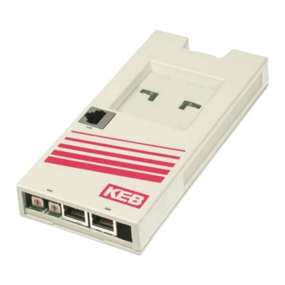
The F5 PROFINET operator is integrated into the frequency inverter housing by plug-in and fits into all F5 devices. Here it concerns to a gateway, which controls the data transfer from PROFINET to the inverter control and reverse. Internally the data are transferred via the serial KEB own protocol with the name HSP5. Order informations... -
Page 5: List Of Literature
Hardware List of literature [1]: Application Layer Protocol for decentralized periphery and distributed automation Specification for PROFINET V2.2 [2]: Application Layer Services for decentralized periphery and distributed automation Specification for PROFINET V2.2 [3]: Profile Drive Technology PROFIdrive Technical Specification for PROFIBUS and PROFINET V4.1 [4]: GSDML Specification for PROFINET IO V2.10 [5]: Application manual of the used frequency inverter control. -
Page 6: Meaning Of The Led Flashing
Double lightning (200 ms ON/200 ms OFF/200 Fatal error occurred during initialization. No ms ON/1000 ms OFF) function of the operator! Can occur e.g.: - No valid KEB MAC address assigned - Inconsistent configuration. Constantly on No error Diagnostic interface X6B (COMBIVIS) RJ45 socket of the diagnostic interface. - Page 7 (reset to default) IP Gateway: 0.0.0.0 242…253 / F2h…FDh Last stored name. Last stored values. IP address: 192.168.0.100 254 / FEh empty IP mask: 255.255.255.0 (KEB production test) IP Gateway: 0.0.0.0 255 / FFh Last stored name. Last stored values. Delivery status...
-
Page 8: Technical Data
Hardware Technical data 2.5.1 Operating conditions Standard Stand- Instructions ard/ class EN 61800-2 Inverter product standard: rated specifications Definition acc. EN 61800-5-1 Inverter product standard: general safety Ambient conditions during operation extended to -10…45 °C (use frost protection for water Temperature Climate cooling systems and temperatures below zero) Humidity 5…85 % (without condensation) -
Page 9: Software
Software Fundamentals of the KEB PROFINET interface The KEB F5 PROFINET interface contains a PROFINET slave controller for time-critical operations of the com- munication. By using this PROFINET interface it is guaranteed that basic communication is compatible to the PROFINET specification. The functionality of the KEB F5 ProfiNet operator is determined by: •... - Page 10 Software The parameter values are only contained in a request with request ID = 2. Request Reference: 1 ... FFh: Serial number for differentiation of the different requests Request ID: Value Meaning Request parameter (Read) Change parameter (Write) Axis-No. = 0, since the F5 PROFINET operator represents an 1:1 gateway. No.
-
Page 11: Parameter Addressing With 16-Bit Pnu Plus 16 Bit Subindex (Profidrive)
PNU = XX80h (*1) The KEB parameter address can be found here or in [5]. It is also possible to display the KEB para- meter address in the KEB start-up software COMBIVIS (more information see annex). -
Page 12: Set-Addressing With Subindex
The PROFINET subindex is used for set-addressing for all KEB parameters. A parameter that contains more than one value is called set-programmable at KEB. These parameters have always eight different values. The 1st value is addressed via set 0 and the last value via set 7. -
Page 13: Error Codes Of The Acyclic Communication
The meaning of these error codes can be taken from the PROFINET specification. 3.1.2 Differences between normal and synchronous mode The KEB F5 PROFINET operator supports the synchronous mode from software version 2.6. This is a special communication between operator and frequency inverter control and is completely independent of the PROFI- NET communication. -
Page 14: Process Data Communication (General)
3.1.3 Process data communication (general) By means of process data communication new process output data (PDOUT) can be sent to the KEB PROFINET slave and the actual process input data (PDIN) can be determined. Which parameters concern to the data is determined by the process data mapping in the frequency inverter control. -
Page 15: Process Data Communication (Normal Mode)
ActiveNrPdins and ActiveNrPdouts. Not all inverter controllers support two internal PDOs for each data direction. Basically the two PDOUT units are realized separately from each other. The KEB-F5-PROFINET-RT operator executes the necessary process data communication to the frequency inverter control one after another, since this communication must be done via the internal serial connection. -
Page 16: Process Data Mapping
3.1.9 PROFINET alarms The KEB-F5-PROFINET operator supports alarms (from software V2.9). This functionality is switched off by default and can be activated via parameter Fb01 FBS Config.Bit7 (if necessary). The operator monitors the value of the inverter parameter ru00 inverter status when the alarm is activated. If there is an error in the inverter (ru00 value <... -
Page 17: Profinet-Name (Dcp-Set)
Configuration (DCP) protocol. The flashing of a LED on the device in a predefined flash patterns can be started and stopped via the DCP set service. The device is addressed via its MAC address (OS10). At KEB F5 PROFINET operator the LED5 serves to this end. -
Page 18: Diagnosis
Diagnosis via the diagnostic interface (X6B) Here the serial interface of a PC is connected with the diagnostic interface (X6B) of the KEB F5 PROFINET ope- rator with a special HSP5 cable (see order data). All parameters of the inverter control and the operator can be responded with the start-up software KEB COMBIVIS. - Page 19 Software If configured that way COMBIVIS addresses the devices via the IP address 192.10.1.x, where x corresponds to the configured node address. The used node address by COMBIVIS for addressing the unit must agree with the adjusted value of parameter Din66019SlvAddr.Please observe from software V2.5 of the F5 PROFINET operator the Din66019SlvAddr is linked to the Pnet_IPAddress by way that Din66019SlvAddr = last digit of Pnet_IPAddress.
-
Page 20: Project Design And Device Description With Gsdml File
Project Design and Device Description with GSDML File A GSDML file is specified as technical manual for PROFINET (see [4]). KEB provides such a technical manual file for the PROFINET slaves. This file is in most cases necessary for a PROFINET configuring tool. The actual version of the KEB F5 PROFINET GSDML file contains no object dictionary and therefore it is not frequency inverter unit-type dependent. -
Page 21: Operator Parameters
Firmware version of the PROFINET-Asics 018Ch OS12: Serial Number Uint32 Serial number of the operator 018Dh OS13: QS number Uint16 KEB internal 018Eh OS14: Uint8 Value of the two hex coding switches at the front NodeSwitchVal of the operator 018Fh OS15: Uint32... - Page 22 Setting of certain commands to the F5 PROFI- NET operator. 0285h Fb05 PDOUT1_Hsp5Service Uint8 Service number for the KEB internal protocol for reading the first 8 bytes PDOUT data 0286h Fb06 PDIN1_Hsp5Service Uint8 Service number for the KEB internal protocol for...
-
Page 23: Parameter Description
Parameter number (PNU): 0181h Subindex: Data type: Int16 Coding: KEB internal Standard value: Level4 password Note: Written and countercheck value are not identical. Currently the password level has no effect on the functionality of the operator and thus has no impor-... - Page 24 Operator Parameters OS02: Name: Software date Meaning Indicates the software date of the actual software. Parameter number (PNU): 0182h Subindex: Data type: Uint32 Coding: First 4 decimal places = year Next 2 decimal places = month Last 2 decimal places = day Standard value: Depending on the actual software version date Note:...
- Page 25 OS11: Name: NetX_FwVersion Meaning Indicates the actual loaded firmware version of the installed ProfiNet Asics. Parameter number (PNU): 018Bh Subindex: Data type: Uint32 Coding: Standard value: Depending on the delivered PROFINET firmware version Note: OS12: Name: Serial number (IM) Meaning Indicates the serial number of the F5 ProfiNet operator.
- Page 26 Operator Parameters OS16: Name: Din66019SlvAddr Meaning Slave address of the F5 PROFINET operator for communication via KEB COMBIVIS with TCP/UDP Parameter number (PNU): 0190h Subindex: Data type: Uint8 Coding: Standard value: Depending on the setting in OS15 Note: This parameter is write protected in the actual software. The value is deter- mined by the least significant byte of the Pnet_IPAddress (OS15).
- Page 27 OS20: Name: Order_Id (IM) Meaning The order number of the KEB F5 PROFINET operator as long character string (20 characters). Divided into five 32-bit values , each with 4 characters. Parameter number (PNU): 0194h Subindex: 1: Character 1 to 4...
- Page 28 Profile_Id (IM) Meaning Profile-ID of the F5 PROFINET operator. Although the KEB F5 PROFINET op- erator operates with respect to the acyclic communication to the PROFIDRIVE profile, it is assigned to the group of Generic device units, because it does not support any parameters according to PROFIDRIVE specification.
- Page 29 OS27 Name: Pnet_IPGateway Meaning Indicates the actual IP Gateway of the F5 PROFINET operator Parameter number (PNU): 0198h Subindex: Data type: Uint32 Coding: 4-byte IP-Gateway Standard value: 0.0.0.0 Note: The last assigned IP Gateway adjustment by the PROFINET controller is stored non-volatile and remains active at the next start-up.From software V3.2 the val- ue of this parameter can also be written via diagnostic interface.
- Page 30 Operator Parameters bit3 = 1 PDAPI_Disable: For the function to be able to exchange acyclic data with a standard Siemens S7 PROFINET controller to PROFIDRIVE Base Mode Parameter Access, the F5 PROFINET operator has a second API with value = 3A00h. The module with the name ,ProfiD- rive_PAP' is assigned to this API.
- Page 31 The adjustment of this parameter is only relevant for the normal mode. Indicates the service code for the KEB internal protocol HSP5 to output the first 8 PDOUT data-byte from the operator to the frequency inverter control. The value must be suitable adjusted to the PDOUT mapping in the frequency inverter.
- Page 32 Meaning The adjustment of this parameter is only relevant for the normal mode. Indicates the service code for the KEB internal protocol HSP5 to read the first 8 PDIN data-byte from the operator to the frequency inverter control. The value must be suitable adjusted to the PDIN mapping in the frequency inverter.
- Page 33 The adjustment of this parameter is only relevant for the normal mode. Indicates the service code for the KEB internal protocol HSP5 to output the second 8 PD- OUT data-byte from the operator to the frequency inverter control, if activated.
- Page 34 Operator Parameters Fb10 Name: CfgNrPDINS Meaning This parameter has two meanings. In mormal mode, the value of this parameter indicates how many PDIN units are activated internally. Each internal PDIN unit transfer 8 bytes PDIN data in normal mode. Additionally the parameter deter- mines which PDIN submodule is configured in slot1.
- Page 35 Fb12 Name: ActiveNrPDINS Meaning Indicates the number of active PDIN units in normal mode.The value of this parameter usually corresponds to the value of FB10. The cause that the two pa- rameter values differ is that the connected frequency inverter control supports only one PDIN unit.
- Page 36 Operator Parameters Fb15 Name: Pdout_Dw1 Meaning Displays the last received first double word (32 bit) of the PDOUT data. Parameter number (PNU): 028Fh Subindex: Data type: Uint32 Coding: Standard value: Note: The value of this parameter can only be read. Fb16 Name: Pdout_Dw2...
- Page 37 Fb19 Name: PdinEvCnt Meaning Counts the events that new PDIN data to the PROFINET have been updated. Parameter number (PNU): 0293h Subindex: Data type: Uint32 Coding: Standard value: Note: The value of this parameter can only be read. Fb20 Name: Pdin_Dw1 Meaning Displays the last transmitted first double word (32 bit) of the PDIN data.
- Page 38 Operator Parameters Fb23 Name: Pdin_Dw4 Meaning Displays the last transmitted 4th double word (32 bit) of the PDIN data. Parameter number (PNU): 0297h Subindex: Data type: Uint32 Coding: Standard value: Note: The value of this parameter can only be read. Fb24 Name: ProjSyncCycleTime...
- Page 39 Fb26 Name: ProjDiffTimePDOUT Meaning Indicates at active PROFINET IO/IRT communication the master projected set- up time where the PDOUT data shall be accepted. Parameter number (PNU): 029Ah Subindex: Data type: Uint32 Coding: 1 µs Standard value: 0 µs Note: The value of this parameter can only be read. Fb27 Name: IRTCycleCnt...
- Page 40 Fb28 Name: 1st PDOUT map Meaning Specifies the PDOUT mapping. The parameter is set-programmable. Parameter number (PNU): 029Ch Subindex: Subindex Bit-coded Linear Meaning FBS Config.Bit6 = 0 FBS Config.Bit6 = 1 addressed the 1th mapping addressed the 1th mapping addressed the 2nd mapping addressed the 3rd mapping addressed the 4th mapping addressed the 5th mapping...
- Page 41 Fb29 Name: 1st PDOUT map count Meaning Indicates how much PDOUT mapping entries shall be activated in 1st PDOUT1 map. Parameter number (PNU): 029Dh Subindex: Data type: Uint8 Coding: Standard value: Note: A changed value is stored immediately active and non-volatile. Fb30 Name: 1st PDIN map...
-
Page 42: Instructions For F5 Profinet Operator At Simatic S7
Instructions for F5 PROFINET operator to Simatic S7 Instructions for F5 PROFINET operator at Simatic S7 Simatic is a product group of Siemens AG. This short overview make no claim to be exhaustive, nor replace the original documents of the company Siemens to this issue! Please note in particular the issue project design of the clock synchronization (PROFINET IO) in the S7 help. - Page 43 PN-IO interface of the CPU and select object properties as a sync master: Then in the right part of the HW Config window of PROFINET-IO → additional field instruments → ..the KEB F5 PROFINET operator selected and appended with the mouse to the PROFINET System in the left pane. It is...
-
Page 44: Additional Project Design For Synchronous Communication According Profinet Io-Irt
Instructions for F5 PROFINET operator to Simatic S7 As standard one 4x16 bit input module and one 4x16 bit output module are automatically inserted for the KEB F5 unit. If required, these can be replaced by one 8x16 bit input module or 8x16 bit output module. The standard project design is used in this example. - Page 45 PROFINET domain management. It makes sense to set the transmit clocking to 2ms, because this corresponds to the minimum setting of the KEB F5 PROFINET slave. Furthermore the KEB slave is selected here (click on ,kebf5-1') and configured as follows...
- Page 46 Instructions for F5 PROFINET operator to Simatic S7 Then the domain management is configured as follows: The Siemens S7 plc provides synchronous alarms for synchronous communication. The exchange of synchro- nous, cyclic data is programmed in this alarm modules. The OB61 is activated for it in the example. This is done by right click to the CPU and selection of ,object characteristics‘.
-
Page 47: Step7 Software
2038 (07F6h). • ‚INDEX' this input parameter defines the data set type which is transacted hereby. For reasons of back- ward compatibility there are several possible values which are treated internally the same by the KEB F5 ProfiNet operator: •... -
Page 48: Cyclic Communication (Process Data)
Instructions for F5 PROFINET operator to Simatic S7 7.3.2 Cyclic communication (process data) Access to the cyclical data of the slave is very simple. Access to entered I/O addresses of a slave defined by the hardware configuration can be done via the following commands: X // Loading the peripheral input word with offset X in ACCU1 Y // Transfer the content of ACCU 1 into the peripheral output word with offset Y Depending on the organization of the cyclic data also the byte or double-word commands can be used (L PID... -
Page 49: Examples For The Setting Of Pd Mappings
Examples for the setting of PD mappings Examples for the setting of PD mappings Mixed mapping (special case) A mixed mapping of 32 bit and 16 bit is a very special PD mapping. In this example the PDOUT data shall be assigned as follows: Sy43 Sy52... - Page 50 Examples for the setting of PD mappings PDIN data: Sy42 Sy51 ru00 ru15 Fb30 PDIN map.Set0 = 002B0110h Sy42 (16-Bit) Fb30 PDIN map.Set1 = 00330110h oP63 (16-Bit) Fb30 PDIN map.Set2 = 0E200110h ru00 (16-Bit) Fb30 PDIN map.Set3 = 020F0110h ru15 (16-Bit) Fb31 PDIN map count...
-
Page 51: Annex
Annex Annex F5 Operator internal error messages Error Communication error during initialisation o_Flo Overflow in value calculation t_out Timeout, control board doesn't answer IDAtA Data invalid rOnly Parameter Read_Only E_Bcc Communication error: wrong checksum Busy Inverter busy ISruc Communication error: Invalid service No PA Parameter locked by password I_FrA... - Page 52 +39 02 3353531 • fax: +39 02 33500790 net: www.keb.de • mail: kebitalia@keb.it KEB Power Transmission Technology (Shanghai) Co.,Ltd. KEB Japan Ltd. No. 435 Qianpu Road, Chedun Town, Songjiang District, CHN-Shanghai 201611, P.R. China 15–16, 2–Chome, Takanawa Minato-ku fon: +86 21 37746688 • fax: +86 21 37746600...
Need help?
Do you have a question about the COMBIVERT F5 and is the answer not in the manual?
Questions and answers