KEB COMBIVERT F5 Instruction Manual
Encoder interface
Hide thumbs
Also See for COMBIVERT F5:
- Applications manual (378 pages) ,
- Reference manual (349 pages) ,
- Instruction manual (196 pages)

Related Manuals for KEB COMBIVERT F5


Summary of Contents for KEB COMBIVERT F5
- Page 1 COMBIVERT INSTRUCTION MANUAL Encoder Interface Channel 1 Resolver Channel 2 variable Mat.No. Rev. DRF5ZEM-K001...
-
Page 3: Table Of Contents
Table of Contents 1. Safety Instructions ..................4 Validity ........................4 1.2 Qualification ......................4 2. Product Description ..................5 General .......................5 Material number ....................5 Scope of delivery (option or replacement delivery) ..........5 Mechanical installation ..................6 3. Description of the Interface ................6 Channel 1 ......................6 3.1.1 Specifications .....................6... -
Page 4: Safety Instructions
The used semiconductors and components of KEB are developed and dimensi- oned for the use in industrial products. If the KEB COMBIVERT is used in ma- Use under spe-... -
Page 5: Product Description
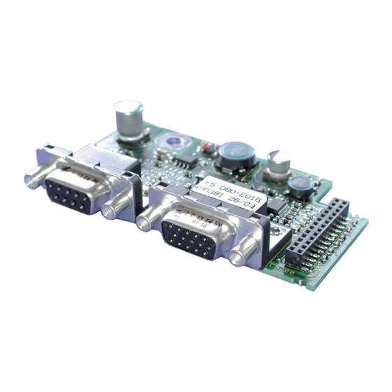
Resolver General Each of the interface cards delivered by KEB include two interfaces. As there are numerous different combinations available each interface will be described by means of separate instructions. The instruction covers the installation of the interface card, the connection as well as the start-up of a suitable encoder. -
Page 6: Mechanical Installation
Resolver at channel 1 Mechanical installation All kind of works on the inverter may be carried out by authorized personnel in accordance with the EMC and safety rules only. • Switch inverter de-energized and await capacitor discharge time • Pull off operator • Remove plastic cover •... -
Page 7: Input Signals Channel 1
Resolver at channel 1 3.1.3 Input signals channel 1 3.1.3.1 Signal tracks A sine-wave voltage is output at terminals REF_HI and REF_LO at the resolver interface. This voltage supplies the field winding in the resolver. This signal is transmitted via a rotary transformer to the rotary part of the resolver. The pulsating magnetic field induces electrical voltages in the two signal windings which are shifted about 90°. The voltages pulsate with the same frequency and phase position as the field signal. However their amplitudes are depending on the position of the rotor winding. -
Page 8: Connection Of The Encoder
Temperature range constant up to 80 °C Color green RAL 6018 3.1.6 Encoder line length The maximum line length of the encoder cable is 50 m. Please contact KEB if longer enco- der cables are required. GB-8... -
Page 9: Tested Encoders
Resolver at channel 1 3.1.7 Tested encoders The following resolvers have been tested by KEB on it application: • Tamagawa TS 2620 N21 E11 (default) • Tamagawa TS 2641 N11 E64 • LTN RE-15-1-A14 • LTN RE-21-1-A05 • Harowe 10BRCX 401 k1C However, this does not restrict the use of rotary encoder with same specifications of other manufacturers. Channel 2 The description of input X3B is depending on the used encoder interface. It is described in a separate manual. -
Page 10: Special Resolver
Resolver at channel 1 Special resolver The use of 2-pole resolvers (pole-pair number 1) is provided as standard. If a resolver with another pole-pair number shall be used, the pole-pair number is to be used as gear factor. Gear factor denominator –––––––––––––––––––––... - Page 11 Notices GB - 11...
- Page 12 KEB Italia S.r.l. fon: +32 5443 7860 • fax: +32 5443 7898 Via Newton, 2 • I-20019 Settimo Milanese (Milano) mail: vb.belgien@keb.de fon: +39 02 33535311 • fax: +39 02 33500790 net: www.keb.it • mail: kebitalia@keb.it KEB Power Transmission Technology (Shanghai) Co.,Ltd. No. 435 QianPu Road, Songjiang East Industrial Zone, KEB Japan Ltd. CHN-201611 Shanghai, P.R. China 15–16, 2–Chome, Takanawa Minato-ku fon: +86 21 37746688 • fax: +86 21 37746600 J–Tokyo 108-0074 net: www.keb.cn • mail: info@keb.cn...
Need help?
Do you have a question about the COMBIVERT F5 and is the answer not in the manual?
Questions and answers