KEB COMBIVERT F5 Instruction Manual
Incremental encoder input htl
Hide thumbs
Also See for COMBIVERT F5:
- Applications manual (378 pages) ,
- Reference manual (349 pages) ,
- Instruction manual (196 pages)

Related Manuals for KEB COMBIVERT F5


Summary of Contents for KEB COMBIVERT F5
- Page 1 C O M B I V E R T INSTRUCTION MANUAL Encoder Interface Channel 1 Incremental Encoder Input HTL Channel 2 03/2008...
-
Page 3: Table Of Contents
Table of Contents GB 1. Product description ................. 4 General ........................4 Description of encoder interface ................4 Material number .....................4 1.4. Scope of delivery (option or replacement delivery) ...........4 Description of the input X3B ................5 Power supply ......................5 1.6.1 Max. load capacity in dependence of voltage supply ..........5 Signal inputs ......................5 1.7.1 Technical data ......................5 1.8.1 Signal characteristic of the HTL encoder ..............6... -
Page 4: Gb 1. Product Description
HTL - Single channel encoder interface Product description General The encoder interface HTL has only one channel. It operates internally with push-pull, so only the +tracks must be connected. The instruction covers the installation of the interface card, the connection as well as the start-up of a suitable encoder. Further information and the parameter adjustments are described in the application manual for the inverter/servo. -
Page 5: Description Of The Input X3B
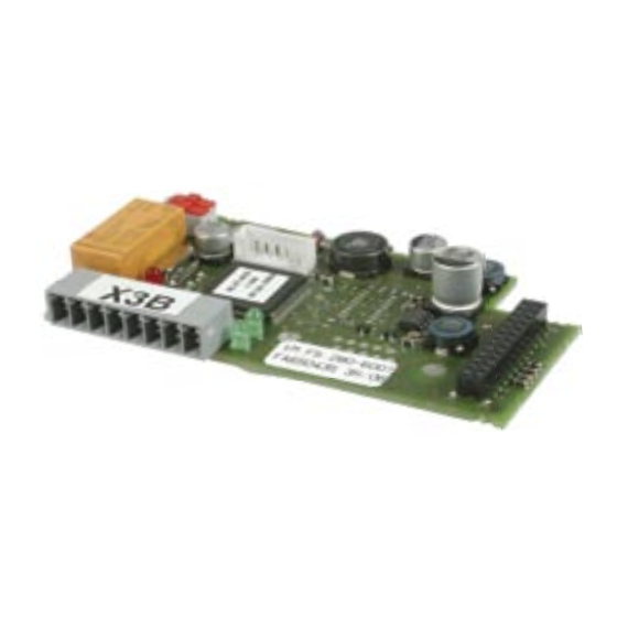
HTL - Single channel encoder interface Description of the input X3B Terminal strip X3B � � � � � � � � Name Description NO contact Error relay NO contact NC contact Error relay NC contact Switching Error relay switching contact contact HTL A+ HTL input track A+ (parallel with X3A.7) -
Page 6: Signal Characteristic Of The Htl Encoder
HTL - Single channel encoder interface Description of the switches and LED’s Switch 200 Track A and B are evaluated Switch 202 only one track is evaluated (dep. of switch 202) Track A is evaluated Track B is evaluated LED301 on: High signal at HTL track B off: Low signal at HTL track B Error relay... -
Page 7: Installation And Start-Up
HTL - Single channel encoder interface Installation and Start-up Mechanical installation All kind of works on the inverter may be carried out by authorized personnel in accordance with the EMC and safety rules only. • Switch inverter de-energized and await capacitor discharge time •... -
Page 8: Tested Encoder
< 10 ms). no communication between interface and control card If Ec.37 <> 16 the COMBIVERT F5-M/S switches off with error 35 "E.EnCC" (error encoder change) when the modulation is switched on. F5-G switches only to error, if encoder channel 1 is activated (S.1 = 0) as actual value source for the speed controller. - Page 9 Notes GB - 9...
- Page 10 Notes GB - 10...
- Page 12 +49 5263 401-0 • fax: +49 5263 401-116 net: www.keb.de • mail: info@keb.de KEB Antriebstechnik GmbH & Co. KG KEB (UK) Ltd. 6 Chieftain Buisiness Park, Morris Close Wildbacher Str. 5 • D–08289 Schneeberg fon: +49 3772 67-0 • fax: +49 3772 67-281...
Need help?
Do you have a question about the COMBIVERT F5 and is the answer not in the manual?
Questions and answers