Invacare rea azalea assist User Manual
Hide thumbs
Also See for rea azalea assist:
- User manual (60 pages) ,
- Manual (48 pages) ,
- Service manual (44 pages)
Table of Contents
Advertisement
Quick Links
Advertisement
Table of Contents

Subscribe to Our Youtube Channel
Related Manuals for Invacare rea azalea assist


Summary of Contents for Invacare rea azalea assist
- Page 1 Rea® Azalea® Azalea®Assist, Azalea®Base, Azalea®Max, Azalea®Minor, Azalea®Tall en Manual wheelchair passive User Manual This manual MUST be given to the user of the product. BEFORE using this product, read this manual and save for future reference.
- Page 2 Corporation or its subsidiaries unless otherwise noted. All information quoted is believed to be correct at time of print. Invacare® reserves the right to alter product specifications without prior consultation. Rea, Rea design and DSS (Dual Stability System) design are registered...
-
Page 3: Table Of Contents
Contents 4.15 Calf pads adjustment......23 4.16 Calf pads — Azalea Max ......23 5 Accessories . - Page 4 Rea® Azalea® 7.4.7 Rear wheels....... . 42 8 Maintenance ........44 8.1 Daily performance check .
-
Page 5: General
If your vision is impaired, you can view the user manual as a PDF file on the Internet at www.invacare.xx (xx = local 1.2 Symbols in this manual country code) and enlarge it on-screen as required. If you cannot enlarge the texts and graphics sufficiently, please In this User Manual warnings are indicated by symbols. -
Page 6: Compliance
“Kit”. Other tests performed on the Azalea Base have also wheelchair is subjected to extreme use. been carried out with the standard backrest and seat from the Azalea range mounted. Invacare can in no way predict the effect of an accident with other configurations. 1488727-M... -
Page 7: Safety
Read them carefully! Contact your local – The handrims may become hot due to friction, Invacare office or Health Care provider in case you need which may cause injury to your hands. assistance. – When mounting accessories etc. be careful not to trap your fingers. -
Page 8: Labels
Rea® Azalea® Azalea Max Location of the serial label WARNING! Risk of tipping forward The purpose of the seat extender is that it should be used together with the chassis extender, otherwise the risk of tipping forward increases. – Always use the seat extender in combination with the chassis extender. -
Page 9: Setup
Setup 3 Setup WARNING! Safety risk The wheelchair may collapse 3.1 Delivery check – Remember to always reinsert and fasten the safety pin when it has been removed. Any transport damage must be reported immediately to – Check that the lock shackle / loop is securely the transport company. -
Page 10: Wires With Backrest Plate
Rea® Azalea® 3. Place both of the wires on the inside of the backrest attachment C. 4. Attach the wires to the backrest tubes E with the straps Fold the slack of the wires under the seat to get them out of the way. With the help of the piston rod resting lip A, the therapist / assistant can loosen the safety pin B for the backrest piston rod C when folding, in order to avoid that the piston and... -
Page 11: Angle Adjustable Legrests
Setup 3.9 Fixed legrests 1. Press and hold in the quick-release button A. 2. Place the rear wheel axle B in the rear wheel attachment C. 3. Pull the wheels outwards to check that the wheel is securely locked in position. WARNING! Risk of injury –... -
Page 12: Components
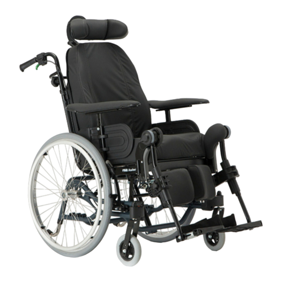
Rea® Azalea® 4.2 Adjusting the tension adjustable backrest 4 Components 4.1 Wheelchair overview 1. Define where you would like to have a firmer support of the back of the user. 2. Have the user leaning forwards and tighten the straps in that region. -
Page 13: Push Handles/Push Bars
Components 4.4 Push handles/Push bars Push bar Azalea Max The following instructions and warnings are valid for all push handles and the push bar: 4.4.1 Height adjustment push handles/push bars Adjusting the height of the connected push handles 1. Loosen the handwheels. A. 2. -
Page 14: Adjusting The Angle Of The Push Bar
Rea® Azalea® 4.4.2 Adjusting the angle of the push bar WARNING! Risk of minor injury Risk of trapping fingers – Be careful when adjusting the angle of the backrest so that the assistant or user do not trap fingers between the backrest and the armrest. -
Page 15: Locking The Tilt And/Or Backrest Angle Adjustment
Components 4.6.3 Locking the tilt and/or backrest angle adjustment in 30 seconds after the last action, before it is automatically deactivated. The hand control can also be manually deactivated by pressing the On/Off button. The force needed to press the buttons on the hand control is 5 Nm (finger power). -
Page 16: Tilt Adjustment Seat
Rea® Azalea® 4.7.3 Tilt adjustment seat 4.7.5 Charging the battery WARNING! Risk of electrical chock – The user must not sit in the wheelchair whilst charging the battery. Damage to the battery – The battery must be loaded 24 hours before using the system the first time. -
Page 17: Tilt Scale Backrest
Components 4.9 Seat adjustments 4.8.1 Tilt scale backrest The seat depth of the chair can easily be adjusted to provide good support. The width between the legrests and armrests and the height of the armrests can also be adjusted. The seat cushion A is secured with Velcro® strips B on the seat plate. -
Page 18: Armrest Adjustments
Rea® Azalea® 4.10 Armrest adjustments 1. Loosen the screw A with an Allen key. Tools: 5 mm Allen Key 4.10.1 Armrest height 2. Adjust the armrests to the desired width. 3. Re-tighten the screw A. Risk of poor adjustment – There must not be any pressure on the armrest / legrest while adjusting the screw. -
Page 19: Legrests
4.10.2 Armrest depth, page 18 4.11 Legrests For users with longer legs, the legrest attachment can be mounted in high position. Contact your Invacare dealer for further information. 1. Pull the lever A with one hand while supporting the 4.11.1 Angle adjustable legrest... -
Page 20: Adjusting The Angle Of The Central Legrest
Rea® Azalea® 4.11.3 Adjusting the angle of the central legrest The adjustment should be done in accordance with the adjustment of the calf pads. Higher adjustments (red-marked area) C are possible, but NOT recommended as the legrest might not be able to support the added weight. -
Page 21: Foot Plates - Footrest
Components CAUTION! Risk of pinching – There must not be any pressure on the amputee support when adjusting the settings. 1. Adjust the angle and the depth by loosening the two screws A at the foot plate attachment. The amputee legrest for Azalea Max are adjustable in Tool: 5 mm allen key angle, depth, sideways and in height. -
Page 22: Tires
Rea® Azalea® 1. The middle part of the footboard converter B is installed WARNING! by inserting the fasteners C into one of the foot plates Risk of breakage and then on the other side. The pressure on the foot plates might cause the 2. -
Page 23: Calf Pads Adjustment
Components 4.15 Calf pads adjustment The calf pads can be fitted in two different depth positions: The calf pads for the Azalea Max are adjustable in angle, 1. Swing the pad forwards. depth and sideways. 2. Unscrew screw A. Angle adjustment: Tools: 5 mm Allen key 1. -
Page 24: Accessories
Rea® Azalea® 5 Accessories CAUTION! Risk of discomfort / minor bruises – Make sure that the elbows of the user 5.1 Headrest / Neckrest are placed on the table when pushing the wheelchair. If the elbows protrudes from the table while pushing the wheelchair, there is a 5.1.1 Height adjustment risk of discomfort or minor bruises. -
Page 25: Swing Away Table
Accessories 5.2.2 Swing away table Swing away function WARNING! 1. Loosen the handwheel A. Risk of injury / bruises 2. Swing the table tray C sideways. – Take care not to hit the user whilst swinging 3. Re-tighten the handwheel A. the table. -
Page 26: Mounting The Attachment For Table Tray
Rea® Azalea® 5.5 Mounting the attachment for table tray 5.6.1 Mounting the half tray Mounting the half tray Mount the table attachment A with the attachment part facing outwards. The plain surface B of the attachment 1. Insert the tube of the half tray A into the attachment should be placed upwards when using the table on the B under the arm pad. -
Page 27: Hemiplegic Armrest
Accessories 5.7 Hemiplegic armrest 5.9 Trunk support 5.9.1 Trunk support with fixed arm The trunk supports can be adjusted in height, depth and sideways. WARNING! Risk of trapping – Be careful not to trap your arm between trunk 1. Loosen the screw A. support and armrest when changing the angle 2. -
Page 28: Trunk Support "Swing-Away
Rea® Azalea® Depth adjustment — multi adjustable cushion 5.9.2 Trunk support “swing-away” 1. Remove the trunk support cover B. 2. Loosen the screws A and adjust to the required height / depth. 3. Re-tighten the screws. The holder for the "swing-away" trunk support is placed in the attachment A on the backrest 1. -
Page 29: Adjusting The Drip Stand
On a seat plate. • On a seat plate with a wedge. • With the H-bracket. Contact your Invacare dealer for more information. CAUTION! Risk of damage The one-piece moulded seat attachments might break. – The back should not be reclined when the Azalea Base is equipped with one-piece moulded seat attachments. -
Page 30: Heel Strap - Azalea Max
Rea® Azalea® 1. Mount the calf strap on the legrest. 5.16.1 Attaching a cover to the single foot plate 2. Wrap the end parts around the legrest tube. 3. Fixate the velcro parts. Both legrests must be in the same angle in order to be able to use the calf strap in the correct way. -
Page 31: Foot Box
Accessories 5.17 Foot box 1. Loosen the nuts C. 2. Adjust the foot box D to the desired angle. WARNING! 3. Re-tighten the nuts C. Risk of injury Fixate the screw with the allen key E and loosen – When using the foot box, the settings the nut with the spanner C. -
Page 32: Posture Belt - Azalea Base
1. Thread the loop F through the fixation on the chair G when transporting the wheelchair in a vehicle, and then through BOTH plastic buckles H. Invacare’s original posture belt must be used as a complement to the safety belt in the vehicle! See chapter: “Transporting wheelchairs with users in vehicles”... -
Page 33: Privacy Attachment
– The attachment A must not be used for safety Invacare’s original pelvic belt must be used as a belts when transferring the user in a vehicle. complement to the safety belt in the vehicle! 5.22.1 Harness attachment holder... -
Page 34: Azalea Minor - Harness
Rea® Azalea® 5. To mount the lower straps, loosen the armrest The harness is mounted on the headrest attachment. attachments with the screws C under the seat. 6. Pull out the attachments approx. 5 cm. 1. Remove the screws for the headrest attachment A and The strap mountings should be fastened from discard them. -
Page 35: Usage
Usage 6 Usage 6.1 General warnings Usage CAUTION! Risk of sliding – The seat must be positioned flat or tilted backwards if the user is left alone unattended. CAUTION! Risk of sliding – If you have a very low seat height and / or 1. -
Page 36: Using The User Operated Brake
Rea® Azalea® Rising from a tilted / reclined position 6.2.6 Using the carer-operated brake WARNING! Risk of reduced brake effect – Incorrect setting or use of the brake reduces the braking effect. Step 1 Step 2 1. Braking when moving: squeeze both brake handles upwards, and the brake will be applied. -
Page 37: Propelling Up A Slope
Usage 6.2.8 Propelling up a slope WARNING! Risk of falling/injury The wheelchair may move forward uncontrollably. – Check the slope to see if there are any particular hazards, potholes, slippery sections. – Never use the user-operated brake to slow down. When you apply the brake on a downward slope, the wheels lock and the wheelchair can suddenly pull to one side, tip sideways or stop immediately. -
Page 38: Kerbs - Alternative Method
Rea® Azalea® 1. Adjust the anti-tip devices upwards. Ensure that the Take particular care if the kerb is wet or slippery. user’s feet rest securely on the footrests and cannot slide off. Then tilt the wheelchair backwards and push it forwards against the kerb. -
Page 39: Transport
However, in situations where conditions defer from the test conditions or where the guidelines in this manual are not followed, Invacare cannot be held responsible for the possible outcome of an accident. Configurations and accessories that are unsuitable to be used as a seat in transportation in a vehicle are mentioned later on in this chapter. -
Page 40: Backrest And Seat Angles
Rea® Azalea® 7.2.1 Backrest and seat angles 3. The pelvic part of the 3-point safety belt must be worn low across the pelvis. The angle of the posture belt shall When transporting an occupied wheelchair in a be within the preferred zone A. vehicle, the recommended angles for backrest and The angle of the posture belt must never exceed seat are the following:... -
Page 41: Frontal Restraints With Straps
Transport 7.3.3 Fastening of posture belt and safety belt 1. Check that the posture belt on the wheelchair is correctly fastened. 2. Fasten the vehicle’s 3-point safety belt around the user. If there is no posture belt in on the wheelchair the user must transfer to the seat of the vehicle. -
Page 42: Backrest Minor
Rea® Azalea® 7.4.2 Backrest Minor 7.4.4 Remove the legrest angle adjustable 1. Push the lever A inwards. 2. Turn the legrest B outwards. 3. Lift of the legrest. 1. Remove the backrest cushion by pulling it forwards, thus separating the velcro® straps. 7.4.5 Remove the footrest fixed 2. - Page 43 Transport 1. Push the quick-release button A. 2. Pull the rear wheel straight out and remove the wheel and the rear wheel axle B from the rear wheel attachment C. 1488727-M...
-
Page 44: Maintenance
Rea® Azalea® 3. Spray the wheelchair chassis with detergent, for example 8 Maintenance a car-cleaning agent with wax, and leave on to work. 4. Rinse the wheelchair chassis with a high-pressure cleaning or ordinary jet of water depending on how dirty 8.1 Daily performance check the wheelchair is. -
Page 45: After Use
Packing Invacare® is continuously working towards ensuring that the • All Invacare Rea AB packing material is developed to fit company’s impact on environment, locally and globally, is the products in an optimal way to reduce unnecessary reduced to a minimum. -
Page 46: Storage
Rea® Azalea® 10 Storage After long-term storage (more than four months) the wheelchair must be inspected in accordance to chapter “Maintenance”. IMPORTANT! Risk of damage to the product – Do not store the product near heat sources. – Never store other items on top of the wheelchair. -
Page 47: Troubleshooting
Troubleshooting 11 Troubleshooting 11.1 Troubleshooting electrical version Symptom Possible cause Remedy End of stroke reached Operate opposite button Battery is not loaded Load the battery Ensure hand control correctly connected Hand control not connected to control unit. Call dealer / technician to replace hand Hand control defective control Tilt or recline does not move... -
Page 48: Technical Data
Rea® Azalea® 12 Technical data 12.1 Dimensions and weights WARNING! Limited access to emergency escape routes – In some combinations, the total width and length of the wheelchair exceeds the recommended measurements for emergency escape routes. – The recommended values concerning access to emergency escape routes are: Length max. 1200 mm and width max. -
Page 49: Maximum Weight Of Removable Parts
Technical data AZALEA AZALEA ASSIST AZALEA TALL AZALEA BASE AZALEA MINOR AZALEA MAX Static 17° 17° 17° 17° 17° 17° stability downhill Static 21° 21° 21° 21° 21° 21° stability sideways Maximum 7° 7° 7° 7° 7° 7° slope with parking brake Leg to seat... -
Page 50: Material
IPx6- The system is protected against water projected from any direction (not high pressure). For full details, also read the documentation from the manufacturer. Download manual(s) from www.linak.com or contact your Invacare dealer. 12.5 Electromagnetic compliance (EMC) General information Products with electronic equipment needs to be installed and used according to the EMC information in this user manual. -
Page 51: Electromagnetic Compliance (Emc) - Manufacturer´s Declaration
Technical data This product has a very low emission and should not interfere with other equipment. However, if other devices nearby should react inexplicably, run and stop this product and observe the devices. • If nothing happens with the other devices, then this product is not causing the error. •... -
Page 52: Service
Rea® Azalea® 13 Service 13.1 Maintenance schedule Check..Weekly Monthly 6 months Action: Recommended air pressure for rear wheels: 50 psi Standard tires 3.5 bar Tire pressure Recommended air pressure for castors: Low profile tires 8” 4.0 bar QR axles rear wheels Pull on the rear wheel to check that the removable axle does not come off. - Page 53 Notes...
- Page 54 Notes...
- Page 55 Notes...
- Page 56 Invacare Sales Companies Ireland: United Kingdom: Invacare Ireland Ltd, Invacare Limited Unit 5 Seatown Business Pencoed Technology Park, Campus Pencoed Seatown Road, Swords, County Bridgend CF35 5AQ Dublin Tel: (44) (0) 1656 776 222 Tel : (353) 1 810 7084...
Need help?
Do you have a question about the rea azalea assist and is the answer not in the manual?
Questions and answers