Invacare Rea Azalea Manual
Hide thumbs
Also See for Rea Azalea:
- User manual (52 pages) ,
- Instruction sheet (6 pages) ,
- Manual (48 pages)
Table of Contents
Advertisement
Advertisement
Table of Contents

Subscribe to Our Youtube Channel
Related Manuals for Invacare Rea Azalea


Summary of Contents for Invacare Rea Azalea
- Page 1 Azalea & ® Azalea Assist ® Manual English...
-
Page 2: Table Of Contents
Contents Product description NB ! Daily performance check Intended use Parts of the wheelchair Lifting the wheelchair Standard equipment Upholstery and frame colours Accessories Technical data Delivery check Assembly Adjustments Seat Sliding seat Legrests/footrests Footplates/calf pads Central legrest Backrest Armrests Seat unit - User and carer-operated chair - Electrically operated chair... -
Page 3: Product Description
Product description Azalea ® Rea ® Azalea is a wheelchair with many adjustment options and accessories. To ensure that you benefit as much as possible from Rea ® Azalea, and in order to do its options justice, the chair must be tested and adjusted by competent personnel. - Page 4 Below you will find a number of points affecting your personal safety. Read them carefully! Invacare is only responsible for product changes carried out by personnel who we authorise. We reserve the right to make any changes to equipment and specifications without prior notice.
-
Page 5: Daily Performance Check
Intended use • The Rea ® Azalea is a manual wheelchair, intended for users who can propel the chair to a certain extent and operate the angle adjustment themselves, and who remain seated for long ® periods. Rea Azalea’s comfort and stability, as well as the option of adjusting the angle of the seat unit and backrest, comprise an ideal combination for activity and comfortable rest. -
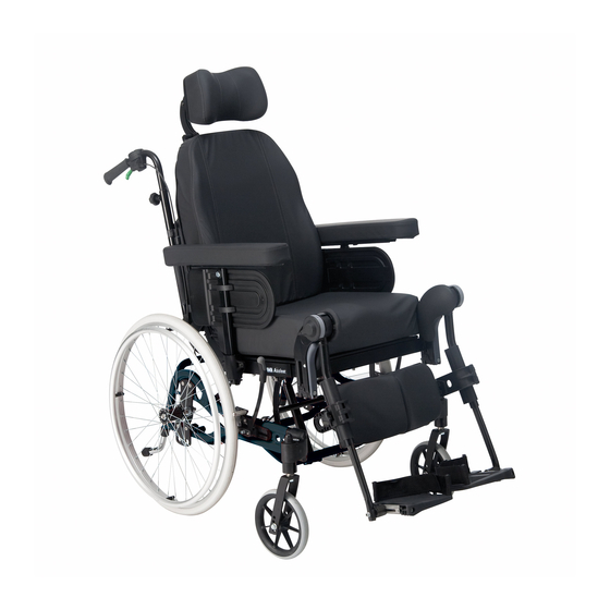
Page 6: Parts Of The Wheelchair
Parts of the wheelchair 1. Backrest 2. Push handle 3. Neckrest 4. Armrest 5. Rear wheel 6. Rear wheel plate 7. Anti-tip device and step tube 8. Brake 9. Castor 10. Seat 11. Legrest 12. Handle for backrest angle and seat tilt adjustment 13. -
Page 7: Standard Equipment
Standard equipment Seat width 39-45/44-50/49-55 cm (39-49/44-54/49-59 cm transit version) Seat depth 43-55 cm Backrest height 62,5 + 20 cm without seat cushion Upholstery and frame colours Upholstery Grey Plush, TR32 Grey Dartex, TR23 Frame colours Pearl Grey Accessories ® Azalea has a wide range of accessories and options. -
Page 8: Technical Data
Cane holder Headrest Headrest with cheek support Neckrest Push bar Push handles braced Pelvic Belt Trunk support Technical data – Rea Azalea (Rea Azalea Assist) 39-45/44-50/49-55 cm 43–55 cm 40/45/50 cm 50-80 cm 24-36 cm (39-49/44-54/49-59 cm) (without seat cushion) 33–50 cm... -
Page 9: Delivery Check
Delivery check Any transport damage must be reported immediately to the transport company. Remember to keep the packag- ing until the transport company has checked the goods and a settlement has been reached. Assembly When you receive your wheelchair, you must fit the backrest, armrests and legrests onto the chair. The assembly is simple and does not require any tools. - Page 10 Legrests/footrests The wheelchair can be equipped with either angle adjustable legrests or fixed footrests. 3a Legrests angle adjustable Attach the legrests by pushing the tube at the upper part of the legrests down into the tubes on the wheelchair. You must angle the legrests outwards when inserting them.
-
Page 11: Adjustments
Adjustments SEAT 1. The seat cushion is secured with Velcro strips on the seat plate. 2. Seat depth You can adjust the depth of the seat by removing the seat cushion and loosening the screws (A) with an Allen key, moving the front edge of the seat forwards or backwards, and then re-tightening the screws. -
Page 12: Sliding Seat
SLIDING SEAT (ACCESSORY) The sliding seat is a great help to the user when moving into or out of the chair. The user must sit in the chair when the seat is moved forwards. Pull the lever (A) upwards at the same time as you pull the handle (B) and move the seat forwards. -
Page 13: Footplates/Calf Pads
FOOTPLATE/CALFPAD 1. Angle-adjustable footplates Adjust the angle and the depth by loosening the screw (A) at the footplate attachment with a 5 mm Allen key. Adjust the footplate to the correct position and retighten the screw. Do not place anything on the footplate when the screw is loose. - Page 14 2. You can adjust the height of the legrest in the following two ways: Alternative 1: Loosen the Allen screw (B) using a 5 mm Allen key on the front of the telescopic tube, place the legrest in the desired position and secure it into place using the Allen screw.
-
Page 15: Backrest
4. Loosen the frontal screw (E) on the side of the tube to adjust the depth of the legrest. Tighten the screw when you have found the desired depth. Repeat this procedure to adjust the depth of the other legrest. 5. - Page 16 2. The upper section has two height levels and it is also removable (to fit lower backrest cushions). Loose screws (B) with an 5-mm Allen key and raise it to its heighest position. For removal, remove the screws (B). Tension adjustable 1.
-
Page 17: Armrests
ARMRESTS Armrest height 1. Adjust the height of the armrests by turning the knob or Allen key screw (A), setting the required height and then re-tightening the knob/screw. Be aware not to trap your fingers between the armpad and the sidesupport when you adjust the armrest height. -
Page 18: Electrically Operated Chair
ELECTRIC TILT AND BACKREST ANGLE ADJUSTMENT 1. Tilt adjustment Tilt the seat unit (seat and backrest) by using the lower part of the control panel. Press (B) to adjust the angle of the seat unit backwards or press (C) to adjust the angle forwards. The hand control should only be used by authorised personell. -
Page 19: Rear Wheels
REAR WHEELS ADJUSTMENT 22”-24” 1-2. You can adjust the height of the seat by moving the rear wheel attachment upwards or downwards. The balance of the wheelchair can be adjusted by moving the rear wheel attachment forward or back- ward. When the attachment is moved forwards, the chair will be somewhat easier to propel, but the risk of tipping will increase. -
Page 20: Wheelchair Heights
2. Rear position (D). Assemble the mounting as illustrated in picture 2. When you have fitted the wheels in the cor- rect position, it is important that you check thoroughly that the nuts and screws are tightened securely. This is important for your own safety! Tool: 5 mm Allen key... -
Page 21: Brakes
BRAKES Start by checking that the tyres have the correct air pressure (printed on the side of each tyre). 1. User brake The user brake is to be used when the chair is not moving, and is not intended for reducing speed when the chair is moving. -
Page 22: Push Handles/Push Bar
PUSH HANDLES BRACED/PUSH BAR 1. Push bar/Push handles braced Loosen the knobs (A). The height of the push- handles braced/pushbar can be adjusted simply by pulling the handles upwards or pushing them downwards. Adjust it to the height that you require and tighten it. -
Page 23: Anti-Tip Devices
ANTI-TIP DEVICES The anti-tip device also acts as a step tube. It is height- adjustable and easy to adjust. 1. Press the spring-loaded buttons (A), raise or lower the anti-tip device and ensure that the spring- loaded buttons (A) pop out into place properly in their new position. -
Page 24: Neckrest
3. The sidewise adjustment is made by loosening screw (E). Adjust and re-tighten. 4. The angle of the wings is adjusted by loosening screws (D). Adjust and re-tighten. NECK REST 1. To adjust the height of the neck rest, first loosen the screw (B) in the stop block, then loosen the handwheel (A). -
Page 25: Abduction Cushion
ABDUCTION CUSHION 1. The height adjustment and removal is operated by the handwheel (A). 2. The depth is adjusted in a forward or backward position. Loosen handwheel (A) and turn. TRUNK SUPPORT With multi adjustable cushion 1. You adjust their height by first loosening the screws (A) whilst moving the attachment (B) upwards or downwards.Re-tighten the screws (A). -
Page 26: Pelvic Belt
• small side support / large trunk support Alt.1 • large side support / small trunk support Alt.2 Trunk support with fixed cushion. The trunk supports can be adjusted in height,depth and sideways. 1. You adjust their height by first loosening the screws (G) whilst moving the attachment (H) upwards or downwards. -
Page 27: Transport
Transport The Rea ® Azalea is easy to prepare for transport. 1. Backrest Remove the backrest cushion by pulling it forwards, thus separating the Velcro straps. Loosen both knobs (A) and pull the backrest directly upwards. Lay the backrest on the seat, where it can remain during transport of the wheelchair. - Page 28 4. Armrests, Pull them straight up 5. Rear wheels Remove the rear wheels by pushing buttom (A) and pulling the wheel straight out. 6. Lifting the wheelchair Always lift the wheelchair by gripping the frame at the points shown in the diagram. Never lift the wheelchair by the removable armrests or the footrests.
-
Page 29: Transport Of Wheelchairs In Vehicles
Remember that the best solution is always to move the user from the wheelchair into a normal car seat. TEST REPORT FROM DYNAMIC SAFETY RESTRAINT TEST Test No Rea ® Azalea: P600377B Customer: Invacare Rea AB Date: 10/02/2006 Test No Rea ® Azalea Assist:... -
Page 30: Observations
• Alterations or substitutions are not to be made to points of the wheelchair or to structural and frame parts without the written consent of Invacare ® •... -
Page 31: Restraint Methods
If pelvic belt on the wheelchair is missing we recommend that the user should transfer to the seat of the vehicle, if possible The safety belt should not be kept from the user’s body by the parts of the wheelchair. Rea Azalea Assist ® Azalea... -
Page 32: Safety Instructions/Propelling Techniques
Safety instructions/propelling techniques We recommend that you have the chair tested by the qualified person who has prescribed the wheelchair, after he or she has made the adjustments that you request, taking your build and needs into account. We hope that you have also received help in learning how best to use the wheelchair. - Page 33 Climbing a kerb This method is for when the assistant is always behind the wheelchair and it creates the greatest safety for the user. The following advice is for the assistant: Illustration 1) Adjust the anti-tip devices upwards. Ensure that the user’s feet rest securely on the footrests and cannot slide off.
-
Page 34: Guarantee
Accidents/Near-accidents Please inform your Invacare office immediately of any accidents or near-accidents that have been caused by this wheelchair and that have led to, or could have led to, personal injury. The relevant authority must also be contacted and reported to. -
Page 35: Recycling
Tyres and tubes are made of rubber and can be recycled according to above. Packing All Invacare Rea AB packing material is developed to fit the products in an optimal way to reduce unnecessary material waste. All boxes are recyclable. - Page 36 Fax: +49 (0)75 6270066 contactsp@invacare.com info@invacare-aquatec.de France Italia Nederland Norge Invacare Poirier SAS Invacare Mecc San s. r. l. Invacare BV Invacare AS Route de St Roch Via dei Pini 62, Celsiusstraat 46, Grensesvingen 9, F-37230 Fondettes IT-36016 Thiene (VI)
Need help?
Do you have a question about the Rea Azalea and is the answer not in the manual?
Questions and answers