Invacare Rea Azalea Series User Manual
Manual wheelchair passive
Hide thumbs
Also See for Rea Azalea Series:
- User manual (56 pages) ,
- Mounting instruction (2 pages) ,
- Service manual (10 pages)
Table of Contents
Advertisement
Quick Links
Advertisement
Table of Contents

Related Manuals for Invacare Rea Azalea Series


Summary of Contents for Invacare Rea Azalea Series
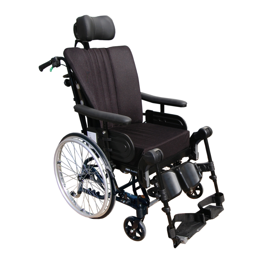
- Page 1 Rea® Azalea® Azalea®Assist, Azalea®Base, Azalea®Max, Azalea®Minor, Azalea®Tall en Manual wheelchair passive User Manual This manual MUST be given to the user of the product. BEFORE using this product, read this manual and save for future reference.
- Page 2 Corporation or its subsidiaries unless otherwise noted. All information quoted is believed to be correct at time of print. Invacare® reserves the right to alter product specifications without prior consultation. Rea, Rea design and DSS (Dual Stability System) design are registered trademarks...
-
Page 3: Table Of Contents
4.13.2 Adjusting the one-piece footrest ....20 Contents 4.13.3 Footboard converter — Azalea Max ... . . 21 4.14 Calf pads adjustment . - Page 4 Rea® Azalea® 8.2 Safety information ......40 8.3 Maintenance electrical version ..... 40 8.4 Cleaning .
-
Page 5: General
Azalea Base have also been carried out with the standard backrest and seat from the Azalea range mounted. 1.4 Limitation of liability Invacare can in no way predict the effect of an accident with other Invacare Rea AB accepts no liability for damage arising from: configurations. -
Page 6: Service Life
The life span may be shorter if the 1.9 Service life wheelchair is subjected to extreme use. We estimate that the Invacare® wheelchair has a service life span of five years. It is difficult to state the exact length of the service life of 1488727-G... -
Page 7: Safety
Below you will find a number of points affecting your personal safety. as this would increase the pressure from the armrests Read them carefully! Contact your local Invacare office or Health to the side of the pelvis. Care provider in case you need assistance. -
Page 8: Symbols On The Labels
Rea® Azalea® Electrical version CLASS II equipment Warning / Caution Product with a thermal fuse Type B Applied Part Applied Part complying with the specified requirements for protection against electrical shock according to IEC60601-1. Safety Isolation transformer, general Location of the electrical information label 2.4 Symbols on the labels General Refer to the user manual. -
Page 9: Setup
Setup 3 Setup 3.1 Delivery check Any transport damage must be reported immediately to the transport company. Remember to keep the packaging until the transport company has checked the goods and a settlement has been reached. 3.2 Assembly When you receive your wheelchair, you either fit the backrest or, on some models, fold up the backrest. -
Page 10: Folding The Backrest - Gas Piston Holder
Rea® Azalea® With the help of the gas piston resting lip A, the therapist / assistant can loosen the safety pin B for the backrest gas piston when folding, in order to avoid that the gas piston and backrest falls to the ground. WARNING! Safety risk The wheelchair may collapse... -
Page 11: Angle Adjustable Legrests
Setup 3.2.6 Angle adjustable legrests 3.2.7 Fixed legrests Push the legrests down into the tubes of the legrest attachment. Push the footrest down into the tubes of the legrest attachment. You must angle the legrest outwards when inserting it You must angle the footrest outwards when inserting it into the legrest attachment. -
Page 12: Components
Rea® Azalea® 4.2 Adjusting the tension adjustable 4 Components backrest 4.1 Wheelchair overview Define where you would like to have a firmer support of the back of the user. Have the user leaning forwards and tighten the straps in that region. -
Page 13: Push Handles/Push Bars
Components 4.4 Push handles/Push bars CAUTION! Risk of trapping fingers The following instructions and warnings are valid for all push handles – Do not trap your fingers between the push handles and the push bar: braced and the neckrest attachment. (If you have a tension adjustable backrest). -
Page 14: Adjusting The Angle Of The Push Bar
Rea® Azalea® 4.4.2 Adjusting the angle of the push bar 4.6.2 Carer-operated tilt adjustment Use the green lever A with the green symbol B on the right Press the buttons A. hand side to tilt the seat unit (seat and backrest). Adjust the push bar B to the preferred angle. -
Page 15: Symbols On The Hand Control
Components 4.7.3 Tilt adjustment seat Risk of malfunction – Work on the handset or other electric parts (motors etc.) should only be carried out by properly trained personnel. When activating the On/Off button, a short “beep” confirms that the hand control is activated. The hand control is active in 30 seconds after the last action, before it is automatically deactivated. -
Page 16: Charging The Battery
Rea® Azalea® 4.7.5 Charging the battery 4.8.1 Tilt scale backrest Damage to the battery – The battery must be loaded 24 hours before using the system the first time. – Unplug the mains cable after loading before the wheelchair is moved. The battery charger has different charging cables in order to adapt to different local electrical standards. -
Page 17: Seat Adjustments
Components 4.9 Seat adjustments Loosen the screw A with an Allen key. Tools: 5 mm Allen Key Adjust the armrests to the desired width. Re-tighten the screw A. Risk of poor adjustment – There must not be any pressure on the armrest / legrest while adjusting the screw. -
Page 18: Armrest Adjustments
CAUTION! For users with longer legs, the legrest attachment can be Risk of trapping fingers mounted in high position. Contact your Invacare dealer for – Be careful not to trap your fingers between the arm further information. pad and the side support when you adjust the armrest height. -
Page 19: Fixed Legrest
Components 4.11.3 Adjusting the angle of the central legrest Loosen the adjustment knob A. Hold the foot plate with the other hand. Adjust to the appropriate leg angle. Re-tighten the knob. WARNING! Risk of trapping fingers When adjusting the foot plate, the fingers might get trapped. -
Page 20: Amputee Legrest
Rea® Azalea® The adjustment should be done in accordance with the adjustment of the calf pads. Higher adjustments (red-marked area) C are possible, but NOT recommended as the legrest might not be able to support the added weight. WARNING! Risk of damage Damage on the mechanism –... -
Page 21: Footboard Converter - Azalea Max
Components The middle part of the footboard converter B is installed by inserting the fasteners C into one of the foot plates and then on the other side. Make sure that the part is turned the right way. If not, it will fall out. -
Page 22: Calf Pads Adjustment
Rea® Azalea® Angle adjustment footboard converter In order to adjust the depth and angle of the footboard converter, remove the middle section of the footboard. See 4.13.3 Footboard converter — Azalea Max, page 21 The calf pads for the Azalea Max are adjustable in angle, depth and sideways. -
Page 23: Using The Carer-Operated Brake
Components 4.17 Using the carer-operated brake Release the handle. WARNING! Risk of reduced brake effect – Incorrect setting or use of the brake reduces the braking effect. Releasing the brakes: squeeze the handle and the lock catch will release automatically. If the brake effect is poor or reduced, contact your authorized representative, i.e your dealer or Health Care provider. -
Page 24: Accessories
Rea® Azalea® The table tray can be adjusted both in depth and width, the following 5 Accessories sections will show the different possibilities. 5.1 Headrest / Neckrest 5.2.1 Adjusting the depth of the table tray 5.1.1 Height adjustment Open the safety lock for the depth adjustment A. The height and the removal are operated by the handwheel. -
Page 25: Mounting The Attachment For Table Tray
Accessories WARNING! Risk of damage Damage on the armrest – Do not put pressure on the front of the armrest, as this could cause damage on the armrest attachment. 5.6 Abduction cushion Place the cushion for the table tray A on the table and place the attachment straps B around the table. -
Page 26: Trunk Support "Swing-Away
Rea® Azalea® Depth adjustment — fixed cushion Angle adjustment — multi adjustable cushion Tools: 5 mm Allen key To adjust the depth of the trunk supports, loosen the screws D Loosen the screw E. with an Allen key. Adjust the cushion to the required angle. Move the trunk support forwards or backwards. -
Page 27: Adjusting The Drip Stand
There are four options how to attach a seat to the Azalea base: • Directly on the seat brackets. • On a seat plate. • On a seat plate with a wedge. • With the H-bracket. Contact your Invacare dealer for more information. 1488727-G... -
Page 28: Calf Strap Padded
Rea® Azalea® CAUTION! Risk of damage The one-piece moulded seat attachments might break. – The back should not be reclined when the Azalea Base is equipped with one-piece moulded seat attachments. 5.11 Calf strap padded Brake lever 5.14 Cover for footrest / foot plate CAUTION! Risk of imbalance Mount the calf strap on the legrest. -
Page 29: Foot Box
However, when transporting the wheelchair in a vehicle, Invacare’s original pelvic belt must be used as a complement to the safety belt in the vehicle! See chapter: 7.2 Transporting wheelchairs with users in vehicles, page 36 See chapter: 5.18 Attachment positioning belt, page 30 for warnings... -
Page 30: Pelvic Belt - Azalea Base
However, when transporting the wheelchair in a vehicle, Invacare’s original pelvic belt must be used as a complement to the safety belt in the vehicle! The pelvic belt is used to prevent the risk of falling or sliding out of the chair and for providing the user with a good See chapter: 7.2 Transporting wheelchairs with users in vehicles,... -
Page 31: Privacy Attachment
However, when transporting the wheelchair in a vehicle, Invacare’s original pelvic belt must be used as a complement to the safety belt in the vehicle! The harness is mounted on the headrest attachment. -
Page 32: Harness Attachment - Azalea Base
Rea® Azalea® Remove the screws for the headrest attachment A and discard 5.20.3 Harness attachment — Azalea Base them. Position washers and harness as shown above. Insert new screws C through the eyelets into the attachment B. Tighten the screws. To mount the lower straps, loosen the armrest attachments with the screws D under the seat. -
Page 33: Usage
Usage 6.1.3 Using the user operated brake 6 Usage 6.1 Operating the wheelchair We recommend that you have the chair tested by the qualified person who has prescribed the wheelchair, after he or she has made the adjustments that you request, taking your build and needs into account. -
Page 34: Propelling Down A Slope
Rea® Azalea® 6.1.7 Climbing a kerb Many experienced users can propel themselves up a slope. In order not to lose control of the steering and to avoid tipping backwards, This method is for when the assistant is always behind the wheelchair you should always lean forwards whilst propelling up a slope. -
Page 35: Escalators And Stairs
Usage Check that the push handles/push bar are securely fixed in place before you start. Fold the anti-tip devices upwards. The assistant steps backwards onto the pavement and pulls the Balance the wheelchair on the rear wheels until the balance point wheelchair up onto the pavement. -
Page 36: Transport
Invacare cannot be held responsible for the possible outcome of an accident. Configurations and accessories that are unsuitable to be used as a seat in transportation in a vehicle are mentioned later on in this chapter. -
Page 37: Restraint Methods
Transport The pelvic part of the 3-point safety belt must be worn low across the pelvis. The angle of the pelvic belt shall be within the preferred zone A. The angle of the pelvic belt must never exceed 75°. Incorrect placement of safety belt The 3-point safety belt must not be held away from the user's body by parts of the wheelchair such as armrests or wheels etc. -
Page 38: Disassembly For Transport
Rea® Azalea® 7.4.2 Backrest Minor WARNING! Risk of injury The user is not securely restrained in the vehicle. – Never use only the pelvic belt as a safety belt during transport. – The vehicle’s 3-point safety belt must always be used to secure the user during transport. -
Page 39: Remove The Legrest Angle Adjustable
Transport 7.4.4 Remove the legrest angle adjustable Push the handle A forwards or sidewards. Turn the footrest B outwards. Lift off the footrest. 7.4.6 Armrest Press and hold the release button A. Remove the armrest. 7.4.7 Rear wheels Push the lever A inwards. Turn the legrest B outwards. -
Page 40: Maintenance
Rea® Azalea® Spray the wheelchair chassis with detergent, for example a 8 Maintenance car-cleaning agent with wax, and leave on to work. Rinse the wheelchair chassis with a high-pressure cleaning or ordinary jet of water depending on how dirty the wheelchair is. 8.1 Daily performance check Do not aim the jet towards bearings and draining holes. -
Page 41: After Use
Invacare® is continuously working towards ensuring that the company’s impact on environment, locally and globally, is reduced • All Invacare Rea AB packing material is developed to fit the to a minimum. products in an optimal way to reduce unnecessary material We comply with the current environment legislation (e.g. -
Page 42: Troubleshooting
Rea® Azalea® 10 Troubleshooting 10.1 Troubleshooting electrical version Symptom Possible cause Remedy End of stroke reached Operate opposite button Battery is not loaded Load the battery Ensure hand control correctly connected to Hand control not connected control unit. Call dealer / technician to replace hand Tilt or recline does not move Hand control defective control... -
Page 43: Technical Data
Technical data 11 Technical data 11.1 Dimensions and weights 1. Seat width 2. Seat depth 3. Seat Height 4. Backrest height 5. Armrest height 6. Legrest length 7. Tilt adjustment 8. Total width 9. Total height 10. Total length 11. Weight 12. -
Page 44: Environmental Conditions
IPx6- The system is protected against water projected from any direction (not high pressure). For full details, also read the documentation from the manufacturer. Download manual(s) from www.linak.com or contact your Invacare dealer. 11.5 Electromagnetic compliance (EMC) General information Products with electronic equipment needs to be installed and used according to the EMC information in this user manual. - Page 45 Technical data Voltage Fluctuations EN 61000-3-3:2008 dc%/dmax/d(t)/Pst Electrostratic Discharge EN 61000-4-2:1995 ±2/4/6kV Contact, ±2/4/8kV Air Radiated Field Immunity EN 61000-4-3:2006 3V/m, 80% 1kHz AM, 80MHz - 2.5 GHz EFT/Bursts EN 61000-4-4:2004 ±2kV L/N/E/LNE Surge Immunity EN 61000-4-5:2006 ±0.5/1kV L-N, ±0.5/1/2kV L-E/N-E Conducted RF Immunity EN 61000-4-6:2007 3V, 80% 1kHz AM, 0.15MHz - 80MHz...
-
Page 46: Service
8” 4.0 bar If you have a flat tire on your wheelchair, contact your Invacare dealer in order to get the flat tire attended to by competent personnel. Pull on the rear wheel to check that the removable axle QR axles rear wheels does not come off. - Page 47 Notes...
- Page 48 Invacare Sales Companies Ireland: United Kingdom: Invacare Ireland Ltd, Invacare Limited Unit 5 Seatown Business Campus Pencoed Technology Park, Pencoed Seatown Road, Swords, County Bridgend CF35 5AQ Dublin Tel: (44) (0) 1656 776 222 Tel : (353) 1 810 7084...
Need help?
Do you have a question about the Rea Azalea Series and is the answer not in the manual?
Questions and answers