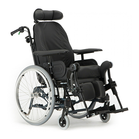
Invacare rea Azalea Assist User Manual
Manual wheelchair passive
Hide thumbs
Also See for rea Azalea Assist:
- User manual (56 pages) ,
- Manual (48 pages) ,
- Service manual (44 pages)
Table of Contents
Advertisement
Quick Links
Advertisement
Table of Contents

Subscribe to Our Youtube Channel
Related Manuals for Invacare rea Azalea Assist


Summary of Contents for Invacare rea Azalea Assist
- Page 1 Rea® Azalea® Azalea® Assist, Azalea® Base, Azalea® Max, Azalea® Minor, Azalea® Tall en Manual wheelchair passive User Manual This manual MUST be given to the user of the product. BEFORE using this product, this manual MUST be read and saved for future reference.
- Page 2 All rights reserved. Republication, duplication or modification in whole or in part is prohibited without prior written permission from Invacare. Trademarks are identified by ™ and ®. All trademarks are owned by or licensed to Invacare Corporation or its subsidiaries unless otherwise noted.
-
Page 3: Table Of Contents
Contents 4.12 Half tray ........27 4.12.1 Mounting the half tray . - Page 4 Rea® Azalea® 8.5.5 Disinfection ....... . 50 9 After Use ........51 9.1 Storage .
-
Page 5: General
Azalea range mounted. Indicates a hazardous situation that could result in serious injury or death if it is not avoided. Invacare can in no way predict the effect of an accident with other configurations. CAUTION Indicates a hazardous situation that could result The Rea Azalea product range has been tested as complete in minor or slight injury if it is not avoided. -
Page 6: Safety
Rea® Azalea® 2 Safety WARNING! Risk of falling – Check that all parts are attached securely to the frame. 2.1 Safety Information – Check that all wheels, knobs, screws and nuts are properly tightened. This section contains important safety information for the –... -
Page 7: Azalea Max And Azalea With Laguna 2 Backrest
Keep in mind that there is no sure – Only use combinations allowed by Invacare. way to determine the effect such modifications Contact your Invacare distributor for will have on the overall immunity of the information. -
Page 8: Labels And Symbols On The Product
Rea® Azalea® 2.5 Labels and symbols on the product Snap hook symbols Depending on the configuration, some wheelchairs may be Identification label used as a seat in a motor vehicle, some may not. The identification label is attached to the frame of your Tie-down positions where the restraint wheelchair and gives the following information: system straps must be placed in case of... -
Page 9: Product Overview
Product Overview 3.3 Main parts of the wheelchair 3 Product Overview 3.1 Product Description This is a passive wheelchair with seat and backrest tilting mechanism and swing-away, angle adjustable leg rests. IMPORTANT! The wheelchair is manufactured and configured individually to the specifications in the order. The specification must be performed by a healthcare professional according to the user’s requirements and health condition. -
Page 10: Parking Brakes
Rea® Azalea® 3.4 Parking brakes 1. Define where you would like to have a firmer support of the back of the user. The parking brakes are used to immobilize the wheelchair 2. Have the user leaning forwards and tighten the straps in when it is stationary to prevent it from rolling away. -
Page 11: Manual Tilt And Backrest Angle Adjustment
Product Overview Carer-operated tilt adjustment WARNING! Risk of tipping The risk of tipping backwards increases when the wheelchair is tilted or reclined The user may slide out of the wheelchair even in a tilted or reclined position – Always use anti-tipper device. –... - Page 12 Rea® Azalea® Backrest angle adjustment CAUTION! Risk of damage to the product – Make sure that the hand control is not unintentionally activated. – Do not let children play with the hand control. – If anything unusual is observed, such as unusual sounds or uneven running during operation, shut down the system.
- Page 13 Product Overview Locking of recline and tilt function 1. Press on the locking key A. 1. Connect the charger cable supplied with the chair into a 2. Keep pressing on the locking key. wall socket. 3. Simultaneously press on the chosen function B for the 2.
-
Page 14: Push Handles/Push Bars
Rea® Azalea® 3.8 Push handles/Push bars CAUTION! Risk of trapping fingers The following instructions and warnings are valid for all push – Do not trap your fingers between the push handles and the push bar: handles braced and the neckrest attachment. (If you have a tension adjustable backrest). -
Page 15: Adjusting The Angle Of The Push Bar
Product Overview 3.8.2 Adjusting the angle of the push bar 3.9.1 Adjusting the seat depth 1. Remove the seat cushion. 2. Loosen the screws A with an 5 mm Allen key. 3. Move the front edge of the seat forwards or backwards. 4. -
Page 16: Armrest Adjustments
Rea® Azalea® 3.10.2 Armrest depth 1. Loosen the screws B. Tools: 5 mm Allen Key 2. Adjust the leg rests to the desired width. 3. Re-tighten the screws B (5–6 Nm). Side rest pad There are two different side rest pads available, one side rest cushion which is placed in the armrest pocket and one side rest pad which is placed directly on the side rest. -
Page 17: Swing Away Leg Rests
Product Overview Hinging IMPORTANT! Risk of damage to the leg rest mechanism 1. Push the leg rest down into its receiver and swing it – Do not place anything heavy, or let children sit forwards until it engages. on the leg rest. Adjusting angle 3.11.1 Swing away leg rests There are six preset positions available for angle adjustment. -
Page 18: Calf Pads - Azalea Max
I (3–5 Nm) in the desired position. folding it down. Invacare recommends that foot plate adjustment is carried out by a qualified technician. To ensure a good position of the feet, two types of straps can be provided;... -
Page 19: Footboard Converter - Azalea Max
Product Overview 1. The middle part of the footboard converter B is installed by inserting the fasteners C into one of the foot plates and then on the other side. 2. Make sure that the part is turned the right way. If not, it will fall out. -
Page 20: Adjusting The Angle Of The Central Legrest
Rea® Azalea® WARNING! CAUTION! Risk of breakage Risk of damage The pressure on the foot plates might cause the The legrest might cause damage to the floor. footboard to break. – When the seat is tilted forwards on a chair –... - Page 21 Product Overview 1. Loosen the handwheel A and adjust to the required angle. 2. Re-tighten the handwheel. 3. Loosen the handwheel B and adjust the calf pad to the required depth. 4. Re-tighten the handwheel. 5. Loosen the screws C and adjust the calf pad sideways. Do not forget to tighten the screws and the handles properly.
-
Page 22: Options
Rea® Azalea® 4 Options 3. Mount the hemiplegic armrest C in the armrest pole. 4. Re-tighten the screw A. 4.1 Headrest/Neckrest 4.1.1 Height adjustment 5. The hemiplegic armrest can be adjusted in angle. The resistance can be increased/decreased by adjusting the screw A. -
Page 23: Trunk Support "Swing-Away
Options Backrest plate Adjustable backrest Tools: 5 mm Allen key Screws height / depth adjustment Attachment position for small side support / large trunk support Height adjustment Attachment position for large side support / small trunk 1. You adjust the height by first loosening the screw / support screws A. -
Page 24: Lateral Positioning Pads (For Adjustable Backrest Cover Only)
Rea® Azalea® 4.5.1 Using lateral positioning pads Tools: 5 mm Allen key / 13 mm fixed spanner. 1. The angle can be adjusted by loosening the screws E 1. Remove the backrest cover A. and bolts D on the trunk support arm. 2. -
Page 25: Tilt Scale
Options 4.7.1 Tilt scale backrest Height 1. Loosen the lever A. 1. Place the tilt scale for the backrest angle G on the push 2. Adjust the drip stand to the desired height. bar/push handle or on the backrest tubes according to 3. -
Page 26: Adjusting The Depth Of The Table Tray
Rea® Azalea® 4.8 Table tray WARNING! Risk of falling / injury – The table must never be used as a replacement for the posture belt. WARNING! Risk of tipping / injury – Max load on the table: 8 kg CAUTION! CAUTION! Risk of discomfort Risk of discomfort / minor bruises... -
Page 27: Add A Table Tray Cushion
Options Depth adjustment Remove the protection paper A from the elbow pads. 1. Loosen the handwheel A. 2. Adjust the table in depth with the table tube B. 3. Re-tighten the handwheel A. Swing away function Place the elbow pads B on the table. 4.11 Mounting the attachment for table tray 1. -
Page 28: Mounting The Half Tray
2. Raise or lower the anti-tip device. 3. Ensure that the spring-loaded buttons A pop out into place properly in their new position. Invacare recommends that anti-tipper height adjustment is carried out by a qualified technician. The anti-tipper has five possible height positions. -
Page 29: Calf Strap Padded
On a seat plate with a wedge. For adjustments, see:6.2.1 Using the User Operated Brake, • With the H-bracket. page 38 Contact your Invacare dealer for more information. CAUTION! Risk of damage The one-piece moulded seat attachments might break. – The back should not be reclined when the Azalea Base is equipped with one-piece moulded seat attachments. -
Page 30: Foot Box
Rea® Azalea® Position adjustment 3. Attach the pre-glued parts of the hook tapes A on the front- and rear side of the footrest. 4. Place the cover C on the one piece footrest. 5. Secure the cover by attaching the loop parts on the 1. -
Page 31: Directional Lock
Options 4.21 Directional lock WARNING! Risk of serious injury during transport WARNING! In a vehicle, a user in his wheelchair must be Risk of injury secured by a safety belt (3-point belt). A posture The directional lock is not a brake. belt only is not sufficient as a personal restraint –... -
Page 32: Posture Belt - Azalea Base
However, when transporting the wheelchair in a vehicle, Invacare’s original posture belt must be used as a complement to the safety belt in the vehicle! See chapter: “Transporting wheelchairs with users in vehicles”... -
Page 33: Harness
Risk of injury mounted by a qualified technician. However, when – The harness has to be fitted and adjusted by a transporting the wheelchair in a vehicle, Invacare’s trained therapist. original posture belt must be used in addition to, but never as a substitute for an approved passenger restraint system (3-point belt)! The harness is mounted on the headrest attachment. -
Page 34: Harness Attachment - Azalea Base
Rea® Azalea® 4.24.3 Harness attachment — Azalea Base 1. Remove the screws for the headrest attachment A and discard them. 2. Position washers and harness as shown above. 3. Insert new screws C through the eyelets into the attachment B. 4. -
Page 35: Setup
Setup 5 Setup 1. Let the piston rest on the lip A for support when mounting the piston. 2. Tilt the backrest slightly forward while supporting the piston manually. 5.1 Safety information 3. Align the holes of piston rod and backrest attachment and slide the safety pin B through them. -
Page 36: Wires With Backrest Plate
Rea® Azalea® 1. Place the wires A and B as shown on the picture above. Risk of damage to the wires – It is important that the cable for the assistant brake A is placed on the inside of the backrest tubes. 2. -
Page 37: Angle Adjustable Leg Rests
Setup 5.10 Fixed leg rests 1. Press and hold in the quick-release button A. 2. Place the rear wheel axle B in the rear wheel To install or remove the Swing away, Fixed leg rest, refer to attachment C. → 3.11.1 Swing away leg rests, page 17. 3. -
Page 38: Using The Wheelchair
Rea® Azalea® brake is operated in the same way as the standard user 6 Using the wheelchair operated brake, the difference is that the brake handle brakes both wheels at the same time. The one arm brake is available both for the right and the left side of the General warnings —... -
Page 39: Move To/From The Wheelchair
Using the wheelchair 6.4 Move to/from the wheelchair WARNING! Risk of overturning There is a high risk of overturning during the transfer. – Only get in and out without assistance if you are physically able to do so. – When transferring, position yourself as far Step 2 Step 3 back as possible in the seat. -
Page 40: Negotiating Steps And Kerbs
Rea® Azalea® 6.6 Negotiating steps and kerbs 1. Move the wheelchair backwards until the rear wheels touch the kerb. WARNING! 2. The assistant should grasp both push handles, push Risk of overturning downwards firmly and tilt the wheelchair backwards so When negotiating steps you could lose your that the front wheels lift off the ground, then pull the balance and tip the wheelchair over. -
Page 41: Stability And Balance When Seated
Using the wheelchair 1. Bend your upper body forwards and propel the wheelchair with quick, powerful strokes on both handrims. 1. Point the front wheels forwards. (To do this, move your wheelchair forwards slightly then back again.) Going down slopes 2. -
Page 42: Transport
Rea® Azalea® 7.3.1 Backrest 7 Transport 7.1 Safety information WARNING! Risk of injury if the wheelchair is not properly secured In the event of an accident, braking manoeuvre, etc. you may suffer serious injuries from flying wheelchair parts. – Always remove the rear wheels when transporting the wheelchair. -
Page 43: Push Handles/Push Bar
Even when the wheelchair is properly secured and the 7.3.6 Armrest following rules are met, injuries to passengers may occur in a collision or sudden stop. Therefore Invacare strongly recommends transferring the wheelchair user to the vehicle seat. Do not make alterations or substitutions to points of the wheelchair (structure, frame or parts) without the written consent of Invacare Corporation. - Page 44 WARNING! – Before journey contact transporter and request Therefore Invacare strongly recommends information about the capability for the below transferring the wheelchair user to the vehicle required equipment. with the posture belt on.
- Page 45 Transport Front side tie-down positions for snap hooks: 1. Attach the snap hooks on the rear straps to the vertical rear tube B by the rear wheel attachment. 2. Attach rear straps to the rail system referring to best CAUTION! practice recommended instructions from the safety belt The directional lock mechanism might break manufacturer.
- Page 46 Rea® Azalea® Fastening the 3-point Passenger Restraint System WARNING! – Ensure the 3-point passenger restraint system fits as tightly across the user's body as possible without discomfort and no part is twisted. – Ensure the 3-point passenger restraint system is not held away from the user's body by parts of the wheelchair such as armrests or wheels etc.
- Page 47 Transport 1. The vehicle's safety belt should fit as tightly across the user's body as possible without discomfort. The upper part of the safety belt should fit over the user's shoulder as illustrated. No part of the safety belt must be twisted. No part of the safety belt must be twisted.
-
Page 48: Maintenance
Check the reclining 2. Tighten any loose bolts with the suitable torque. and tilting Therefore refer to the Service Manual, available on the mechanisms internet at www.invacare.eu.com. Check the castors IMPORTANT! Self-locking screws/nuts or thread-locking Check bolts adhesive are used for several connections. If... -
Page 49: Maintenance Electrical Version
Check that no air is escaping from the tyre. fluids, – before using it for a new user. Spare parts All spare parts may be obtained from an Invacare 8.5.3 Cleaning authorized provider. IMPORTANT! Dirt, sand and seawater can damage the bearings and steel parts can rust if the surface is damaged. -
Page 50: Washing
Rea® Azalea® Cleaning upholstery The fabric can be washed at temperatures up to 60º C. Normal detergents can be used. For cleaning upholstery refer to the instructions on the labels of the seat, cushion and backrest cover. All parts of the wheelchair with multi stretch polyurethane (PU) coated fabric upholstery, such as If possible, always overlap hook and loop strips (the armrest pads, calf pads, headrest or neckrest, should... -
Page 51: After Use
After Use The disposal and recycling of used products and packaging 9 After Use must comply with the laws and regulations for waste handling in each country. Contact your local waste management company for information. 9.1 Storage IMPORTANT! 9.2.1 Disposal Electrical Version Risk of damage to the product WARNING! –... -
Page 52: Troubleshooting
Rea® Azalea® 10 Troubleshooting CAUTION! – If you notice a fault with your wheelchair, e.g. a significant change in handling, stop using your wheelchair immediately and contact your 10.1 Safety information provider. Faults may arise as a result of daily use, adjustments or changing demands on the wheelchair. -
Page 53: Identifying And Repairing Faults
Troubleshooting 10.2 Identifying and repairing faults Fault Possible cause Action The wheelchair does not Incorrect tyre pressure on one rear wheel Correct tyre pressure, → 11.2 Tyres, page 56 travel in a straight line One or more spokes broken Replace faulty spoke(s), → qualified technician Spokes tightened unevenly Tighten loose spokes, →... -
Page 54: Technical Data
Rea® Azalea® 11 Technical Data 11.1 Dimensions and weights All dimension an weight specifications refer to a wide range of the wheelchair in a standard configuration. Dimension and weight (based on ISO 7176–1/5/7) may alter according to different configurations. IMPORTANT! –... -
Page 55: Maximum Weight Of Removable Parts
Technical Data AZALEA AZALEA ASSIST AZALEA TALL AZALEA BASE AZALEA MINOR AZALEA MAX Leg-to- 105° – 180° 105° – 180° 105° – 180° 105° – 180° 105° – 180° 105° – 180° seat- surface angle Armrest-to- 240–360 mm 240–360 mm 240–360 mm 240–360 mm 240–360 mm... -
Page 56: Tyres
Rea® Azalea® 11.2 Tyres The compatibility of the tyres listed above depends on the configuration and/or model of your wheelchair. The ideal pressure depends on the tyre type: The table below is an indication. In case the tyre differs The size of the tyre is mentioned on the sidewall of from the list below, check the side of the tyre, the maximum the tyre. -
Page 57: Electrical System - Models Equipped With Electric Tilt And Backrest
IPx6. See label and label on each electric device for correct IP class. The lowest IP-classification decides the overall classification of the system. IPx6- The system is protected against water projected from any direction (not high pressure). For full details contact your Invacare authorized provider. 11.7 Electromagnetic compliance (EMC) General information Products with electronic equipment needs to be installed and used according to the EMC information in this user manual. - Page 58 Rea® Azalea® EN 61000-4-8 Magnetic Field Immunity 3A/m, 50Hz-80Hz Dips & Interruptions EN 61000-4-11 -95%/-60%/-30% 1488727-R...
- Page 59 Notes...
- Page 60 Invacare distributors United Kingdom: New Zealand: Invacare Limited Invacare New Zealand Ltd Pencoed Technology Park, Pencoed 4 Westfield Place, Mt Wellington 1060 Bridgend CF35 5AQ New Zealand Tel: (44) (0) 1656 776 222 Phone: 0800 468 222 Fax: (44) (0) 1656 776 220 Fax: 0800 807 788 uk@invacare.com...
Need help?
Do you have a question about the rea Azalea Assist and is the answer not in the manual?
Questions and answers