Table of Contents
Advertisement
Quick Links
T30A / T60A Tape Library
<T30A>
-This User's Guide provides information to use the unit safely and correctly and to avoid a
personal injury and/or a damage to the customer's properties. Thoroughly read this manual to
fully understand handling of the unit.
-Keep this User's Guide with the unit to see whenever it is necessary.
-Make sure to provide this User's Guide along with the unit to a third party.
NF6303 / NF6306
User's Guide
Rev.1
<T60A>
856-129409-460-A
Advertisement
Table of Contents
Troubleshooting

Related Manuals for NEC T30A


Summary of Contents for NEC T30A
- Page 1 T30A / T60A Tape Library NF6303 / NF6306 User’s Guide Rev.1 <T30A> <T60A> -This User's Guide provides information to use the unit safely and correctly and to avoid a personal injury and/or a damage to the customer's properties. Thoroughly read this manual to fully understand handling of the unit.
-
Page 2: Handling Of Laser Product
Chinese acceptance statement Taiwan acceptance statement WEEE Disposing of your used NEC product In the European Union EU-wide legislation as implemented in each Member State requires that used electrical and electronic products carrying the mark (left) must be disposed of separately from normal household waste. -
Page 3: Fcc Acceptance Statement
FCC acceptance statement This equipment has been tested and found to comply with the limits for a Class A digital device, pursuant to Part 15 of the FCC Rules. These limits are designed to provide reasonable protection against harmful interference when the equipment is operated in a commercial environment. This equipment generates, uses, and can radiate radio frequency energy and, if not installed and used in accordance with the instruction manual, may cause harmful interference to radio communications. -
Page 4: Safety Precautions
Safety Precautions Before use, In order to use the product safely and correctly, be sure to read over this book, please handle it properly. This product has been designed with sufficient safety. In case of improper use of this product, the operator may be injured and damage to property may result. - Page 5 (Example) Symbol to draw attention Term indicating a degree of danger Description of a danger Disconnect the power cord(s) before installing or removing the product. Make sure to power off the product and disconnect the power cord(s) from a power outlet before installing/removing the server.
- Page 6 NEC assumes no liability for any accident resulting in personal injury, death, or property damage if the product has been used in the above conditions.
- Page 7 Rack Do not overload the supply circuit by connecting this equipment with other equipment so that the total exceeds the outlet rating. To prevent fires, wiring and device damage, the total power drawn by the equipment in the rack shall not exceed the rating of the branch circuit. Contact your electric constructor or the local power company for the requirements on the wiring and installation of electric facilities.
- Page 8 Elevated Operating Ambient. If installed in a closed or multi-unit rack assembly, the operating ambient temperature of the rack environment may be greater than room ambient. Therefore, consideration should be given to installing the equipment in an environment compatible with the maximum ambient temperature (Tma) specified by the manufacturer.
- Page 9 Power Supply and Power Cord Use Do not hold the power plug with a wet hand. Do not disconnect/connect the plug while your hands are wet. Failure to follow this warning may cause an electric shock. Do not connect the ground wire to a gas pipe. Never connect the ground wire to a gas pipe.
- Page 10 Use the authorized power cord only. Use only the power cord that comes with your product. Use of an unauthorized power cord may cause a fire when the electric current exceeds the rated flow. Also, observe the following to prevent an electric shock or a fire caused by a damaged cord. ・Do not stretch the cord harness.
- Page 11 Do not use any unauthorized interface cable. Use only interface cables provided by NEC and locate a proper device and connector before connecting a cable. Using an unauthorized cable or connecting the product to an improper destination may result in a fire by short circuit.
- Page 12 Treat optical fiber cables with care and respect. Rough treatment of optical fiber cables could cause deterioration of characteristics or mechanical damage (line disconnection). ・Ensure a minimum bending radius of 38mm. ・Do not drop a cable on the floor or otherwise shock it. ・If not connecting a cable, place caps on it.
- Page 13 Cleaning and Working with Internal Devices Do not disassemble, repair, or alter the product. Never attempt to disassemble, repair, or alter the product on any occasion. Failure to follow this instruction may cause an electric shock or fire as well as malfunctions of the server.
- Page 14 During Operation Do not use the product if any smoke, odor, or noise is present. If smoke, odor, or noise is present, immediately turn off the product and disconnect the power plug from the outlet, then contact your service representative. Using the product in such conditions may cause a fire.
-
Page 15: Warning Labels
(Do not remove or soil these labels.) If any of these labels are missing, removed, soiled, or otherwise unreadable, contact your local maintenance service company. Warning Label Meaning / Location T30A [Do not disassemble] Only the maintenance Personnelcan disassemble the unit. -
Page 16: The Mark Of This Manual
The mark of this manual The following signs are used in this manual. Kind of display Kind Content It explains the content for which attention is especially necessary in operating. It explains information on the limitations in the operation. It explains amplification of the text. -
Page 17: Table Of Contents
Contents Handling of laser product ....................i Japanese acceptance statement ..................... i Chinese acceptance statement ....................i Taiwan acceptance statement ....................i WEEE ..........................i FCC acceptance statement ....................ii ICES acceptance statement ....................ii ... - Page 18 1.7.8 Attachment of label plate....................25 1.8 Removal of shipment Stabilizer ....................26 Chapter2 Setup ......................... 27 2.1 Connection of a Interface Cable ....................27 2.1.1 Connection of SAS Cable ....................27 2.1.2 Connection of FC Cable ..................... 28 2.2 Connection of AC Power Cable ....................29 2.3 Power-On and self test......................
- Page 19 4.5.6 Setting of Active Slot ......................63 4.6 Insertion and Removing Cartridge by Operator Panel ..............64 4.6.1 Magazine Operations ......................64 4.6.1.1 Removing Magazine ..................... 64 4.6.1.2 Insertion of cartridges into magazine ................66 4.6.1.3 Removal of cartridges from magazine ................66 4.6.1.4 Emergency removal of magazine ...................
- Page 20 6.1.3.1 Master Key ........................ 126 6.1.3.2 Encryption Key ......................127 6.1.3.3 Backup of encryption key ................... 127 6.2 Basic Operation of encryption key management function ............128 6.2.1 Setup ..........................128 6.2.1.1 Registering the activation key ..................129 6.2.1.2 Checking the license key registration status ..............129 6.2.1.3 Enabling the encryption key management function ............
- Page 21 9.4 Cleaning of Magazine Filter ....................161 9.5 Cleaning of cartridge ......................161 9.6 Updating the Firmware ......................162 9.6.1 Confirming the Firmware Version ..................162 9.6.2 Updating the Library Firmware ..................163 9.6.3 Updating the Drive Firmware ................... 164 9.7 Troubleshooting Procedures ....................
-
Page 22: Figures
Figure 1-10 Rack mount rail attachment position................19 Figure 1-11 attachment of rack mount rails .................. 20 Figure 1-12 attachment of rack mount bracket R(left:T30A , right :T60A) ........21 Figure 1-13 attachment of rack mount bracket L(left:T30A , right :T60A) ........21 Figure 1-14 Mounting of library onto rack ................... - Page 23 Figure 5-23 Date and Time setup ....................107 Figure 5-24 SMTP setup ......................108 Figure 5-25 SNMP setup ......................109 Figure 5-26 SNMPv3 setup ....................... 110 Figure 5-27 Trap list........................111 Figure 5-28 Encryption Basis setup .................... 112 Figure 5-29 Encryption Detail setup ................... 113 Figure 5-30 Licenses Registration ....................
- Page 24 Tables Table 1-1 Status LED on OperatorPanel..................3 Table 1-2 Button on OperatorPanel ....................4 Table 1-3 Status LED on Magazine Operation panel ............... 5 Table 1-4 Button on Magazine Operation panel ................5 Table 1-5 Drive Sled ingicator ....................10 Table 1-6 component list of rack mount kit parts ................
-
Page 25: Preface
Preface This User's Guide describes the operation (mainly for the hardware) of the T30A and T60A Tape Library (hereinafter called "T30A Library" or "T60ALibrary" or ”Library”). Refer to the manual of the backup software for commands and console messages of backup software. -
Page 26: Exemptions
Exemptions (1) NEC assumes no liability arising from the use of this product, nor any liability for incidental or consequential damages arising from the use of this manual regardless of Item (5) on the previous page. (2) NEC assumes no liability for the data stored in memory (data cartridge) regardless of existence of an error or a failure. - Page 27 This page is intentionally blank. - - xxvi...
-
Page 28: Chapter1 General Description
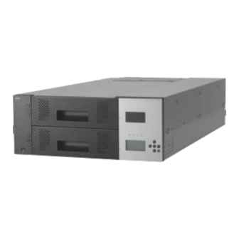
This chapter describes the major hardware components of the library system and the system specifications. The T30A tape library is an automated tape management system that contains one or two LTO Ultrium drives. This library can house up to 30 cartridges. -
Page 29: Names And Features Of Components
Figure 1-1 Front of the Library (Above: T30A/Below: T60A) (1).Magazine operation panel (When the front panel is removed, the Ethernet connector for maintenance is found inside.) (2).Magazine (T30A has one magazine, and T60A has two magazines (upper and lower).) (3).Operator panel... -
Page 30: Operator Panel
1.3.2 Operator panel The operator panel has LEDs that indicate the status of the library, an LCD panel that displays the library status, operations, messages, library settings, error messages, etc., and buttons used to operate the library. Figure 1-2 Operator panel 1.3.2.1 Status LED The following four LEDs are included in the operation panel. -
Page 31: Lcd
1.3.2.2 LCD The LCD panel displays the library state, operations, messages, library settings, error messages, etc. The LCD panel has a built-in backlight LED and is backlit when the operator panel is used. If you disable the Auto Backlight OFF function on the OP Panel Settings menu, the backlight is automatically turned off if the specified time elapses without any operation being performed. -
Page 32: Magazine Operation Panel
1.3.3 Magazine operation panel Figure 1-3 Magazine operation panel(left:T30A,right:T60A) 1.3.3.1 Magazine Status LED Table 1-3 Status LED on Magazine Operation panel This LED indicates the internal status of the I/O station. When the I/O station is closed: On: The I/O station contains one or more cartridges. -
Page 33: Ethernet Connector For Maintenance
1.3.3.3 Ethernet connector for maintenance When the front bezel of the magazine operation panel is removed, the Ethernet connector for maintenance is found inside. The Ethernet connector for maintenance is used for logging in to the remote management interface as a user with maintenance personnel authority. (The IP address of the maintenance port is 192.0.2.1.) In the Ethernet connector for maintenance, a remote administration interface can be used like the... -
Page 34: Magazine
1.3.4.1 Slot number The slot numbers range from 1 to 30 for T30A and from 1 to 60 for T60A. In each column, the slot in the back has the smaller slot number. -
Page 35: Active Slot
“4.4.2.1 Library Settings ” If you enable the I/O station, the magazine slot numbers shown below are assigned to the I/O station slots. Slot numbers: 29/30 for T30A; 59/60 for T60A. By default, the I/O station function is disabled. 1.3.4.4 Escape slot This slot is used to temporarily store tape cartridges when moving tape cartridges inside this product. -
Page 36: Rear View
1.3.5 Rear View (4) (5) (6) (7) Figure 1-5 Components on the Rear of the Library(T30A) Figure 1-6 Components on the Rear of the Library(T60A) (1)Power supply (In case of T60A,the redundant power supply might be installed) (2).AC power connector (3).Drive... -
Page 37: Drive Sled Ingicator
1.3.6 Drive Sled Ingicator These indicate the states of the drive. Table 1-5 Drive Sled ingicator LED indicating the status and maintenance requirements :Maintenance request status. Off :normal. LED indicating the status of power supply :Power is supplied. Off :Power is not supplied. LED indicates the communication status to the library :Recognized from the library. -
Page 38: Power Module Led
1.3.7 Power Module LED Three LED that shows the following is mounted on the back side of the power source module. ・AC:When the AC voltage is supplied, it lights. ・DC:When the DC voltage is supplied, it lights. ・Alarm:When abnormality occurs by the power source module, it lights. -11-... -
Page 39: Encryption
1.4 Encryption This function allows you to encrypt cartridges by setting either an encryption key automatically generated from the master key or a separately specified encryption key to the drive. The library stores encryption keys and manages them individually on a cartridge-by-cartridge basis using barcode labels. -
Page 40: Disposal Of The Product And Comsumables
To avoid data leakage, it is strongly recommended to erase the data completely using your backup software. For information about how to erase data, see the manual of the backup software. NEC is not liable for any leakage of data resulting from improper data erasure. -13-... -
Page 41: Unpacking
1.6 Unpacking 1.6.1 Unpacking The rack mount kit includes the following parts. 1. Unlock the strap (two places). 2. The exterior box has two fasteners, called joints, one on each side. Pull the tab at the right end of the joint toward you and remove the joint. 3. - Page 42 4. Remove the cushioning material to take out the library. 5. Open the plastic bag, and remove the library. -15-...
-
Page 43: Installing The Rack Mounting Kit
1.7 Installing the Rack Mounting Kit 1.7.1 Components The rack mounting kit consists of the components shown below. ⑤(T30A) ⑥(T30A) ⑦ ① ⑧ ② ⑨ ③ ④ ⑤(T60A) ⑥(T60A) Figure 1-7 Components of Rack mount kit parts Table 1-6 component list of rack mount kit parts... -
Page 44: Caution Points For Rack Mounting
1.7.2 Caution points for rack mounting Racks that hold the Autoloader must meet the requirements described in <1> to <4> below. Confirm this by referring to the figure below and by taking measurements. <1> According to the EIA standard, the rack must have a 19-inch universal pitch. <2>... -
Page 45: Figure 1-9 Rack Dimensions
<4> The rack's internal dimensions must meet the dimension requirements shown in Figures A to C below. [unit: mm] Mounting brackets Front door Rear door Enlarged view of X area Figure 1-9 Rack Dimensions Table 1-7 internal Dimension Requirements for rack Site Description Requirement... -
Page 46: Rack Mount Rail Attachment Position
1.7.3 Rack mount rail attachment position Attach four flat head screws (M6) each to the front and back of the rack to attach the rack mount rails. Rack mount rail 2U Library bottom <front of rack> Rack mount rail 2U Library bottom <back of rack>... -
Page 47: Attachment Of Rack Mount Rail L/R
1.7.4 Attachment of Rack mount rail L/R Perform the following steps to attach the left and right rack mount rails. <1> Use four flat head screws (M6) to attach the rack mount rail L to the front and rear of the rack. <2>... -
Page 48: Attachment Of Rack Mount Bracket L/R
<2> Use four screws (M3) to attach the rack mount bracket L to the left of the library. screws(M3) screws(M3) Rack mount bracket R Figure 1-12 attachment of rack mount bracket R(left:T30A , right :T60A) Rack mount bracket L screws(M3) screws(M3) -
Page 49: Installation Of Library
Especially, the rack (44U etc.) with height is not fixed to the delicate state by the stabilizer etc.Transport and set it up while supporting the rack by two people or more. T30A T60A Figure 1-14 Mounting of library onto rack... -
Page 50: Figure 1-15 Attachment Of Rack Ears
Use two screws (M5) to attach the left and right of the Library's front side. T30A T60A Figure 1-15 attachment of rack ears -23-... -
Page 51: Attachment Of Rack Ear
1.7.7 Attachment of Rack ear Attach the left and right rack ears to the left and right of the Library's front side. T30A T60A Figure 1-16 Fastening of Library’s front side -24-... -
Page 52: Attachment Of Label Plate
1.7.8 Attachment of label plate Attach the label plate with repetition belt to the left of library ‘s back side. Figure 1-17 attachment of label plate -25-... -
Page 53: Removal Of Shipment Stabilizer
1.8 Removal of shipment Stabilizer The Library has a screw that is fastened to its rear side to stabilize the internal Accessor during shipment. Before using the Library, be sure to unfasten this screw. Make sure that the shipment stabilizer screw has been unfastened. If the power is turned on while the screw is still fastened, operation faults may occur If the error message "***CHK*** CODE:[0009]"... -
Page 54: Chapter2 Setup
This section describes how to connect the product to a server or switch by using an interface cable. The T60A library can house up to four drives, and the T30A library can house up to two drives. 2.1.1 Connection of SAS Cable Connect each SAS drive of the library to a server by using an SAS cable. -
Page 55: Connection Of Fc Cable
2.1.2 Connection of FC Cable Connect the FC drive of the product to a server or switch by using an FC cable. The product has an FC connector on the back. Be sure to connect the FC cable to Port A. Before connecting the cable, remove the white protection caps. -
Page 56: Connection Of Ac Power Cable
2.2 Connection of AC Power Cable After connecting the signal cable, insert the AC power cable's plug into the Library's AC power connector. Make sure that the plug is fully inserted. When the redundant power supply is installed in the library, insert the AC power cable’s plug into each Library’s AC connector. -
Page 57: Diagnostic Test
2.6 Diagnostic Test Load the diagnostic cartridge in the library, and execute the diagnostic test. For information about Diagnosis test how to perform this test, see "9.2 ." 2.7 Operation Checks after Installation After installing and setting up the library, connecting the cables, executing the diagnostic test, and loading the cartridges, check the following: 1. -
Page 58: Chapter3 Power-On And Power-Off
Chapter3 Power-On and Power-Off 3.1 Power-On and Power-On Sequence Turning on the power of the product initiates a self test. The self test takes several minutes, but no other operation can be performed during the test. Before turning on the power, check that the fastening screw for transportation has been Removal of shipment Stabilizer removed (see "1.8 "). -
Page 59: Chapter4 Operator Panel
Chapter4 Operator Panel This chapter describes how to use the operation panel and how to enter settings for the Library and the cartridge drive. Settings can be entered for the Accessor and the drive only after the Library has been reset. 4.1 Panel Indications The library unit has three screens. -
Page 60: Status Display Screen
4.1.2 Status Display screen [Status Display screen] changes its display when no button operation is performed within certain period of time on [Menu screen], or when Cancel button is pressed on [TopMenu] menu. Shown below is the [Status Display screen]. The [Status Display screen] has the [Library State] that displays a status of library and [Drive State] that displays a status of drive. -
Page 61: Figure 4-3 Accessor Icon
Table 4-1 Library Status displayed in the Operation Panel Message Description PLEASE INSERT MAGAZINE Magazine insertion is requested. MAGAZINE UNLOCKED Magazine is not locked. PLEASE CLOSE I/O STATION I/O Station CLOSE is requested. Initialization is in progress. INITIALIZING・・・ Inventory is in progress. INVENTORY・・・... -
Page 62: Figure 4-4 Magazine Icon
3.Magazine status display section Indicates the status of magazines on the library unit. rear Upper Magazine front Upper Center Lower Magazine Lower 18slot Magazine 12slot Magazine Figure 4-4 Magazine Icon When the magazine is Opened, the display changes as shown below. (In this example,Lower Magazine is Opened.) Figure 4-5 Magazine Icon(Magazine is Opened) When I/O Station is set, it is displayed as follows. -
Page 63: Figure 4-7 Magazine Icon (I/O Station Is Opened)
Figure 4-7 Magazine Icon (I/O Station is opened) Graphic changes into each slot in the magazine depending on the number of cartridge storage as follows. Moreover, a blink indication of the cartridge which the media error generated is given. Data slot I/O Station Figure 4-8 Magazine Icon(Slot Image) 4. -
Page 64: Drive State
4.1.2.2 Drive State In this example, library state that installed four half-Height drives is displayed. Drive State is composed of the following. 1. Drive Icon Indicates the status of tape drive installed in the library unit. Indicates whether a cartridge tape exists in the drive. Table 4-3 Drive Status Icons Indicates that no cartridge tape is inserted into the tape drive. - Page 65 3. Display mode Icon Indicates the current mode of [Status Display screen]. (LIBRARY STATE / DRIVE STATE) 4. Prevent Icon Indicates the prevent status of the drive. When this icon is displayed, it is shown that it is a state of Prevent.
-
Page 66: Asynchronization Message Screen
Indication: Demanding the Magazine lock release from the main management task unlocked (T60A) Message off: End of lock release Magazine Unlocked of Magazine is unlocked(T30A) Indication: End of lock release Message off:Opening the Magazine or in 60 seconds without opening the magazine Upper Magazine Unlocked of Upper Magazine... -
Page 67: Menu Tree
4.2 Menu Tree Table 4-6 Menu tree of commands Top Menu Submenu Commands Move Cartridge Unload Clean Drive Shipping Move Reboot Drive Reboot Library Library State Online / Offline Drive State Online / Offline Selecting of drive Warning Clear -40-... -
Page 68: Table 4-7 Menu Tree Of Configuration
Table 4-7 Menu tree of configuration Top Menu Submenu Configuration Library Settings I/O station Enable / Disable Active Slots Auto Cleaning Mode Enable / Disable Library Mode Random Mode Sequential Mode Loop Mode Enable / Disable Autoload Mode Enable / Disable Cleaning Notice Near Expired Enable / Disable... -
Page 69: Table 4-8 Menu Tree Of Current Information
Top Menu Submenu Current Information Setting Information Library Setting Network Settings Drive Settings OP Panel Settings Slot Information T30A View Magazine View Drive View Escape Slot View Accessor T60A View Upper Magazine View Lower Magazine View Drive View Escape Slot... -
Page 70: Table 4-9 Menu Tree Of Service
Table 4-9 Menu tree of Service Top Menu Submenu Service View Error Status View Library Error View Drive Error Diagnostics Library Verify Drive Diagnostics Perform R/W Test Media Test Head Test Statistics View Accessor Data View Retry Data View Error Data Clear Accessor Data Clear Retry Data Clear Error Data... -
Page 71: Login
4.3 Login Login is required before removing the Library's magazine, entering settings, or using the operation panel's functions. 1) After the library unit is powered on and diagnosis of accessor starts. 2) Diagnosis of accessor is completed, the menu screen as shown below appears. 3) Enter the password on this menu screen. -
Page 72: Service Login
4.3.1 Service Login Input with the password entry screen, "3776". It is displayed as the password error. Service login can be done when inputting once after it returns to the screen of three, "2355". 【Service Login in “Login Mode Disable”】 Push the right-and-left button of an operator panel for 10 seconds. -
Page 73: Top Menu
4.4 Top Menu After Log in, the following screen is displayed. Figure 4-9 Root screen of Top Menu -46-... -
Page 74: Commands
4.4.1 Commands Use the COMMANDS menu when moving the cartridge in the library or cleaning the drive through operator panel. Table 4-11 Commands Submenus Submenu item Default Description Move Cartridge Use this menu to move a cartridge in a slot to another slot of the library. -
Page 75: Configuration
4.4.2 Configuration This menu is used to enter settings for the Library and the drive. Table 4-12 Configuration Submenus Submenu item Description Library Settings This submenu can be used to enter various Library settings. Network Settings This submenu can be used to enter various network-related settings. Drive Settings This submenu can be used to enter various drive settings. -
Page 76: Library Settings
Default Description I/O Station Disable Enable or disable the I/O station. Active Slots T30A:30 Sets the number of data slots and the active/inactive setting. T60A:60 Each logical library can be set. Auto Cleaning Mode Disable Enable or disable auto cleaning. -
Page 77: Network Settings
4.4.2.2 Network Settings Table 4-14 Network Setting Submenu Submenu item Default Description Link Speed Auto Negotiation This sets the network's communications mode. To use the auto setting, select "AUTO". Protocol Stack IPv4 Only Setting of Protocol Stack IPv4 Setting Setting of IPv4 network IPv6 Setting Setting of IPv6 network Table 4-15 IPv4 Setting Submenu... -
Page 78: Drive Settings
4.4.2.3 Drive Settings Table 4-17 Drive Settings Submenu Submenu item Default Description Port-A Setting of Port A of the selected drive. Port-B Setting of Port B of the selected drive. A set content is the same as PortA. The license is necessary for the setting. -
Page 79: Op Panel Settings
4.4.2.4 OP Panel Settings Table 4-19 OP Panel Settings Submenu Submenu item Default Description Auto Backlight OFF Disable This sets the panel's contrast. ・Enable This sets the time until the LCD back light is automatically shut off. ・Disable This disables the LCD back light auto off function. -
Page 80: Current Information
4.4.3 Current Information Current information about library, network, drives, cartridges in the library are displayed. Table 4-21 Current Information submenu Submenu item Description Setting Information Use this menu to view the configuration of the library. Slot Information Use this menu to view the information of the cartridge stored in the library. -
Page 81: Service
4.4.4 Service This menu is used to check or test errors in the Library or drive. Table 4-24 Service submenu Submenu item Description View Error Status This checks the errors in Library or the drive. Diagnostics This diagnoses Library. At least one data cartridge is needed to diagnose Library. Statistics This checks the statistics information in Library. -
Page 82: Statistics
4.4.4.3 Statistics This menu is used to check the statistics information in Library. Table 4-27 Information to be displayed on Statistics Submenu item Description View Accessor Data This checks the statistics information in the Accessor. View Retry Data This checks the statistics information in the Retry. View Error Data This checks the statistics information in the Error. -
Page 83: Advanced Service
4.4.4.7 Advanced Service This menu is used to test of Library. (Do not use it usually. ) Table 4-29 Test to be displayed on Advanced Service Submenu item Description Mechanism test The following mechanism test can be executed. (Do not use it usually. ) ・Demo (Slot-Drv-Slot) ・Demo (Slot-Slot) ・MSBF Test... -
Page 84: Configuring The Library
4.5 Configuring the Library This section describes Library configuration,setting of the drive, changing of the password , and setting for I/O station. 4.5.1 Viewing Configuration data of the library Take the following steps to view the configuration data of the library. 1) [Login]. - Page 85 Once the above message is displayed, the new password is valid. If the entered passwords do not match, the following message will appear. If the above message is displayed, start again from step 4). -58-...
-
Page 86: Setting Of Drive
4.5.3 Setting of Drive This section describes how to set configuration for tape drive installed in the unit. 1) [Login]. See Section 4.3Login for detail. 2) Select [Configuration]. 3) Select [Drive Settings] from [Configuration]. 4) Select the drive to set change. 5) Refer to 4.5.3.1at the SAS drive. -
Page 87: Setting Of Fibre Channel
4.5.3.2 Setting of Fibre Channel This section describes how to set Fibre channel interface configuration for tape drive installed in the unit. In case of FC drive, set drive path , topology , loop ID , Link Speed and robot control path. 1) The following screen will appear after selecting SAS drive. -
Page 88: Setting Robot Control Path
4.5.3.3 Setting robot control path This section describes how to set robot control path. 1) [Login]. See Section 4.3Login for detail. 2) Select [Configuration]. 3) Select [Drive Settings] from [Configuration]. 4) Select the drive that sets the robot control passing. 5) Select Enable under Media Changer Path. -
Page 89: Power Save Mode
4.5.3.4 Power Save Mode This section describes how to set Power Save Mode. 1) [Login]. See Section 4.3Login for detail. 2) Select [Configuration]. 3) Select [Drive Settings] from [Configuration]. 4) Select the drive that sets power save mode. 5) Select Enable under Power Save Mode.(Default:Enable) 6) Selecting [Enable], the screen which inputs time to shift to an energy conservation mode is indicated. -
Page 90: Setting Of I/O Station
4.5.5 Setting of I/O Station You can configure the library unit to use a part of the front magazine as I/O station. Described below is the setting procedure. 1) [Login]. See Section 4.3Login for detail. 2) Select [Configuration] 3) Select [Library Settings] from [Configuration]. 4) Select [Enable] of [I/O station] from [Library Settings]. -
Page 91: Insertion And Removing Cartridge By Operator Panel
4.6 Insertion and Removing Cartridge by Operator Panel This section describes how to insert and remove the cartridge from the library by the operation of the operator panel using the magazine and I/O station. 4.6.1 Magazine Operations 4.6.1.1 Removing Magazine Magazine parts are composed of front magazine and rear magazine. - Page 92 Described below is the procedure to remove rear magazine. The rear magazine is drawn out to the position of the following picture with drawing out the front magazine. 6) A rear magazine is drawn out according to the procedure3),4) similar to the procedure for drawing out the front magazine.(Refer to follwing picture about the location of release lever of fall prevention lock) Please do not draw out the magazine strongly.
-
Page 93: Insertion Of Cartridges Into Magazine
4.6.1.2 Insertion of cartridges into magazine When inserting cartridges into the slots of the magazine, note the direction of each cartridge. If a cartridge is inserted in the wrong direction, malfunctions may occur. Refer to the photo below before inserting. For description of magazine slot numbers, see”... -
Page 94: Emergency Removal Of Magazine
4.6.1.4 Emergency removal of magazine This removal method should be used only during an emergency. When the magazine is taken out in case of things except the necessity by the following operations, neither the library device operation, the drive device nor the tape cartridge can be guaranteed. Moreover, please note that it causes the breakdown of the transportation device ([accessor]) and the magazine when the tape cartridge is taken out while operating. -
Page 95: I/O Station Operations
4.6.2 I/O Station Operations The I/O station dashes out to a device front side after pressing the enter button. Please there must not be danger from which the hand is placed between the moving part, and do not affix the hand to the magazine, and do not put the finger in the opening of the magazine until the I/O station dashes out. -
Page 96: Using The Operation Panel To Move Cartridges
4.7 Using the operation panel to move cartridges 4.7.1 Load cartridge into drive The following describes how to use the operation panel to move a cartridge from a specified magazine slot into the drive. In this example, the cartridge in slot 1 will be loaded into the drive #1. 1) [Login]. -
Page 97: Figure 4-12 Select Destination Screen
6) Select [slotxx] under [Destination], and the slot where the no cartridge is stored is displayed. In this example, slect Drive1. Figure 4-12 Select Destination Screen 7) Select [Execute], the cartridge is moved and inserted into the drive. Figure 4-13 Select Execute -70-... -
Page 98: Removing From The Drive
4.7.2 Removing from the drive This operation should be performed only during emergencies, such as when the operation cannot be controlled from a host device. The following describes the steps for moving a cartridge from the drive. In this example, the cartridge in drive 1 will be removed into the slot1. 1) [Login]. -
Page 99: Figure 4-16 Select Destination Screen
6) Select [slotxx] under [Destination], and the slot where the no cartridge is stored is displayed. In this example, slect Slot01. Figure 4-16 Select Destination screen 7) Select [Execute], the cartridge is ejected from the drive and moved to the slot. Figure 4-17 Select Execute -72-... -
Page 100: Cleaning
4.8 Cleaning 4.8.1 Cleaning by Operation panel Before using the operation panel to set cleaning, make sure that the backup software will not be executing any jobs during the cleaning process. (If necessary, take measures such as turning off the backup software service.) ・Use a special cleaning cartridge with a bar code label that supports the drive to be cleaned. -
Page 101: Rebooting The Library
4.9 Rebooting the Library If a reset is executed without first executing the following steps, the device and/or cartridge may be damaged, and data may be lost. A reboot (initialization) is required in the following cases. ・When a system administrator or maintenance engineer has ordered a reboot of the Library. ・When errors have occurred in the Accessor and/or drive. -
Page 102: Rebooting Drive
4.10 Rebooting Drive If a reset is executed without first executing the following steps, the device and/or cartridge may be damaged, and data may be lost. A reboot (initialization) is required in the following cases. ・When a system administrator or maintenance engineer has ordered a reboot of the Library. ・When errors have occurred in the Accessor and/or drive. -
Page 103: Chapter5 Remote Manager Interface
Chapter5 Remote Manager Interface This chapter describes how to use the Library's Ethernet functions ((Remote Manager interface), SNMP Agent, and email notification). 5.1 Connection Configuration The following configuration is required when using Ethernet functions. (1)General ・10BASE-T/100BASE-TX/1000BASE-T LAN(full duplex or half duplex is OK, Gateway is accessible) (2)Remote Manager Interface Web browser... -
Page 104: Connection Settings
5.2 Connection Settings When using the Library's Ethernet function, the following items must be set appropriately. These items can be set and checked via the operation panel. For description of how to change these settings, see “4.4.2 ”. Configuration Consult with a network manager concerning the settings for these items. Table 5-1 Connection Setting (IPv4) Item Default value... -
Page 105: Startup Of Remote Manager Interface
5.3 Startup of Remote Manager Interface Open a Web browser from any network-connected terminal, and enter the IP address that was set for the Library as the URL. Figure 5-1 Input URL If this product and the terminal are normally connected with the network respectively, the log in screen is displayed as the first stage screen. -
Page 106: Connection Of Https
5.3.1 Connection of https The connection method to the remote manager interface in https is as follows. (1) Https://(IP address set to the tape device) is input. (2) When connecting it with the Web service not registered on the attestation site like the remote manager interface, warning is displayed as shown. -
Page 107: Login Formats
5.4 Login Formats (1)Registered users Up to six users can be freely set. The administrator / service is already registered as the reserved user, so the total number of users, including the reserved user and the freely selectable users, is 15. (Reserved user) User type Username... -
Page 108: Web
5.5 Web Page Configuration The page configuration shown by the browser can be divided into a banner section and a section of specific information for each page. Although the web page can be viewed on an 800 × 600-dot monitor, at least 1280 × 1024 dots is recommended. -
Page 109: Web
5.6 Web Page Detail All windows (except for the login window) display the following menus. Therefore, the user can easily jump to any of these menus from any window. 5.6.1 Menu windows The following are the menus displayed in each window after login. When any of these menus is selected, it changes to a color different from the color of the other menus. -
Page 110: Login
5.6.2 Login [Function] Login to the Web Manager. Authentication is performed by username and password. The three access authority level (administrator, super user and general user) is set according to the username entered. Then, go to the Home page. [Display contets] 1.Account Enter username to login. -
Page 111: Library Information Viewing Menu(Monitor Sytem)
5.6.3 Library information viewing menu(Monitor Sytem) 5.6.3.1 Library Basic Information(System Summary) [Monitor System]-[System Summary] All users [Function] This menu shows the image and basic information of the Library Figure 5-4 Library Basic Information Window -84-... - Page 112 [Information] 1. Device image A photo of the device is shown. 2. Status Library name: Library name Library : Library status (Ready,Not Ready / Dergraded / Failed / PSU n Fault / PSU n FAN Error) ・Failed : The library error was detected. ・Degraded : The mechanism has reached its durability.
-
Page 113: Library Detailed Information Window (Library Map)
5.6.3.2 Library Detailed Information Window (Library Map) [Monitor System] - [Library Map] All users [Function] This menu describes the cartridges loaded in various slots and the Library's various parts. [Information] This window includes detailed information along the right side, which varies according to the selected Accessor, drive, etc. -
Page 114: Figure 5-6 Detail(Magazine)
1. Library Map This shows the physical positions of cartridges stored in the Library, as well as images of the Library's various components such as the Accessor and drive. 2. Details (Magazine) (1)Slot Information This section shows detailed information about the selected slot. Slot type : Indicates the type of slot. -
Page 115: Figure 5-7 Accessor Information
3. Details (Others) (1)Accessor [Accessor information] This section shows detailed information about the Accessor. Status : Indicates the Accessor's status. (Ready, Degraded, Failed, Not Ready, etc) Error information : Displays the event information including an error that occurred in the accessor and an event of articles of consumption exchange notification. -
Page 116: Figure 5-8 Library Information
(2)Library [Library information] This section shows detailed information about the library. Accessor Status : Indicates the Accessor's status. (Ready,Degraded,Failed,Not Ready,etc) Drive n status : Indicates the drive's status. (Ready / Degraded / Failed / Drive FAN Error / Media Error / Cleaning Request) Magazine n status : Indicates the magazine's status. -
Page 117: Figure 5-9 Network Information
(3)Network [Ethernet information] This section shows detailed information about the Ethernet. Status : Indicates the Ethernet's status. Link Speed : Indicates the Ethernet link speed. MAC address : Indicates the Library's MAC address. Library WWNN : Indicates the Library's World Wide Node Name. Protocol : Indicates the currently set protocol. -
Page 118: Figure 5-10 Notification Information
(4)Notification This section shows detailed information about the SMTP / SNMP. SMTP Setting SMTP server : Indicates the IP address of mail server. Sender address : Indicates the e-mail address of library. Subject : Indicates the subject of e-mail the library sends. MailRecipients : Indicates the mail address. -
Page 119: Figure 5-11 Drive Information
4. Details (Drive) (1)Drive n information This section shows drive information. Status : Indicates the drive's status. (Ready / Degraded / Failed / Drive FAN Error / Media Error / Cleaning Request) Element Status:Indicates the drive’s element status. Vendor ID : Indicates the LTO drive manufacturer Product ID : Indicates the drive's product name. -
Page 120: Library Management Menu (Manage Library)
5.6.4 Library management menu (Manage Library) 5.6.4.1 Move Cartridge window (Move Cartridge) [Manage Library]-[Move Cartridge] Service/Administrator/Super user [Function] This window's functions are similar to those of the operation panel's [Move Cartridge] menu, which moves the cartridges by specifying the source and destination of each cartridge to be moved. [Use method] Specifying the source element address and the destination element address to move cartridge. - Page 121 1. Specify source slot Sepecify the source element address to transfer the cartridge.The slot where the cartridge is stored is displayed. Element Address can be narrowed with Row and Slot. 2. Specify destination slot Sepecify the destination element address to transfer the cartridge.The slot where no cartridge is stored is displayed.
-
Page 122: Unload Drive Window (Unload Drive)
5.6.4.2 Unload Drive window (Unload Drive) [Manage Library]-[Unload Drive] Service/Administrator/Super user [Function] This window's functions are similar to those of the operation panel's [Unload] menu, which enables a cartridge that has been inserted in the drive to be unloaded, and displays an unload completion dialog box when this operation is completed. -
Page 123: Clean Drive Window (Clean Drive)
5.6.4.3 Clean Drive window (Clean Drive) [Manage Library]-[Clean Drive] Service/Administrator/Super user [Function] This window's functions are similar to those of the operation panel's [Clean Drive] menu, which inserts a cleaning cartridge into the drive specified by the selected slot, and then cleans the drive. When drive cleaning is finished, the cleaning cartridge is returned to the original slot, and the cleaning complete dialog box is displayed. -
Page 124: Library State (Offline/Online)Switching Window(Library State)
5.6.4.4 Library State (OFFLINE/ONLINE)switching window(Library State) [Manage Library] - [Library State] Service/Administrator/Super user [Function] This function is similar to the operation panel's [Library State] menu's function that switches the Library's setting for the Accessor between online and offline. [Use method] 1. -
Page 125: Library Setting (Configure Library)
5.6.5 Library setting (Configure Library) 5.6.5.1 Account setting (User Access) [Configure Library] - [User Access] Service/Administrator [Function] This window is used to add, modify, or remove users with login access. To add a user, use the Select Action scroll box to select "Add User", and to remove a user, first select the current user to be removed, then use the Select Action scroll box to select "Remove Users". -
Page 126: Figure 5-18 Add A User
[Adding a new user] 1. When "Add User" button is clicked, users can be newly registered. 2. After entering items in the Add a User window, click "Submit" to register a new user. [Information] Figure 5-18 Add a User 1. User name Enter the user name to be registered. -
Page 127: Figure 5-19 Remove A User Confirmation Screen
【Removing a current user】 1. Select the user to remove from Current Users list. 2. When "Remove" is selected, the following dialog box is displayed. 3. Select "Yes" to remove the user. Figure 5-19 Remove a User confirmation screen The user himself cannot be deleted. Service cannot be displayed the user of the Admin authority, be changed, and be encrypting set deleted effectively. -
Page 128: Physical View (Physical)
5.6.5.2 Physical View (Physical) [Configure Library] - [Physical] Service/Administrator [Function] This window is used to set the Library name. [Information] Figure 5-20 Physical 1. Library name The Library's name can be registered. 2. Power Save mode Configure the power save mode of a drive. Enable: Power-save mode validity Disable: Power-save mode invalidity Time to shift to power-save mode further is set up at the time of Enable. -
Page 129: Library Setup Window (Logical)
5.6.5.3 Library setup window (Logical) [Configure Library] - [Logical] Service/Administrator [Function] This window is used to set the Library's operation mode, I/O slot, and number of active slots. [Information] (10) (11) Figure 5-21 Logcal -102-... - Page 130 Use:valid Specify whether to use the slots #59 and #60 as I/O station.(T60A) Specify whether to use the slots #29 and #30 as I/O station.(T30A) 3. Number of active slots This can be used to set the Library's active slots.
- Page 131 10. Drive n ports Sets drive n ports. In case of SAS drive, sets Drive Path,Link speed. In case of FC drive, sets Drive Path, topology , Loop ID, and Link speed. 11. Submit button Click this button to confirm the settings. When complete, a Normal End message will appear. -104-...
-
Page 132: Network Setup Window (Network)
5.6.5.4 Network setup window (Network) [Configure Library] - [Network] Service/Administrator [Function] This window is used to set up network connections. [Information] Figure 5-22 Network setup 1. Ethernet setting Link Speed: The network's link speed can be set as “Auto”, ”10Base-T Full”, “10Base-T Half”, “100Base-TX Full”, “100Base-TX Half”, “1000Base-T Full”,or “1000Base-T Half”. - Page 133 4. IPv6 Settings When "Use IPv6" is checked, the IPv6 protocol is used for communications. Obtain an IP address automatically(Stateless Auto Config): Information is retrieved from a router advertisement, and the IPv6 address, prefix length, and gateway are set automatically. Obtain an IP address automatically(DHCP): Information is retrieved by DHCP, and the IPv6 address, prefix length, and gateway are set automatically.
-
Page 134: Date And Time Setup Window (Date And Time)
5.6.5.5 Date and Time setup window (Date and Time) [Configure Library] - [Date and Time] Service/Administrator [Function] This window is used to set the Library's calendar/clock function. [Information] Figure 5-23 Date and Time setup 1. NTP server This sets time updating from the Time Server (NTP server) as enabled or disabled. Enable: Time information is retrieved from the NTP server. -
Page 135: Event Notification Setup Window(Smtp)
5.6.5.6 Event Notification setup window(SMTP) [Configure Library]-[SMTP] Service/Administrator [Function] This window is used to set the destination to notify the Library information via email. [Information] Figure 5-24 SMTP setup 1. Send Setting SMTP server address: Specify the mail server's IP address or domain name. Sender address:Specify this Library's email address. -
Page 136: Event Notifications Setup Window (Snmp)
5.6.5.7 Event Notifications setup window (SNMP) [Configure Library] - [SNMP] Service/Administrator [Function] This window is used to set the destination to notify the Library information via SNMP. [Information] Figure 5-25 SNMP setup 1. SNMP Enabled The SNMP function is made effective. Trap is not transmitted in the state where SNMP Enabled is not checked. -
Page 137: Figure 5-26 Snmpv3 Setup
Location: Set the device's physical location. Contact: Set contact information. SNMPv3 engine ID: The SNMPv3 Agent's Engine ID may have to be set for the manager. 3. Submit button This button is used to confirm settings. When the Submit button is clicked, the entered values are checked and are set when normal. -
Page 138: Figure 5-27 Trap List
5. Trap List Enter the addresses to be notified via SNMP trap when the specified event occurs in the Library. When clicking address part, following screen is displayed. After setting “Address”, “User name”, “Authentication” and “Privacy”, click “Submit" to register a trap list. -
Page 139: Encryption Basis
5.6.5.8 Encryption Basis [Configure Library] - [Encryption Basis] Administrator [Function] This window is used to set the encryption basis setting. Please refer to section Chapter6 for details. [Information] Figure 5-28 Encryption Basis setup 1. Library Managed Encryption This sets library managed encryption setting as enabled or disabled. 2. -
Page 140: Encryption Detail
5.6.5.9 Encryption Detail [Configure Library] - [Encryption Detail] Administrator [Function] This window is used to set the encryption basis setting. Please refer to section Chapter6 for details. Figure 5-29 Encryption Detail setup -113-... -
Page 141: Licenses Registration
5.6.5.10 Licenses Registration [Configure Library] - [Licenses Registration] Service/Administrator [Function] This window is used to input the activation key to make the function of the option effective. Figure 5-30 Licenses Registration -114-... -
Page 142: Saving The File Setting / Restore Screen (Save And Restore)
5.6.5.11 Saving the File Setting / Restore Screen (Save and Restore) [Configure Library] - [Save and Restore] Service/Administrator [Function] This window is used to save a present setting calue and restore the saved set value. The setting of the device can be succeeded by restoring the data saved when the maintenance chassis are exchanged to a new maintenance chassis. - Page 143 5. Drive Replacement It is used at the time of the maintenance work of a drive. 1) Check Remove of the drive to exchange and click Execute. 2) Remove a drive. 3) Attach the drive of service parts. When you take over to the drive after exchanging the drive serial number before exchange, a case checks.
-
Page 144: Library Maintenance (Service Library)
5.6.6 Library maintenance (Service Library) 5.6.6.1 View Library Logs [Service Library]-[Operator Interventions] All users [Function] Displays only the event log related to the library. [Display Contents] Figure 5-32 View Library logs 1. Select log Select the displayed log. (Command log / Error log / Retry log / Mechanical Motion log / Event log / encryption log / Cleaning log) 2. -
Page 145: Download Library /Drive Logs (Download Logs)
5.6.6.2 Download Library /Drive logs (Download Logs) [Service Library] - [Download Logs] All user [Function] This downloads the library’s logs and the drive's logs.Click the [Download] button to download these logs. In the case of download of the drive’s log, the drive becomes offline. [Display Contens] Figure 5-33 Download Logs 1. -
Page 146: Reset (Reset Library / Drive)
5.6.6.3 Reset (Reset Library / Drive) [Service Library]-[Reset Library and Drives] Service/Administrator [Function] Reset the library or drive. [Display contents] Figure 5-34 Reset Library / Drive 1. Target device Select "Loader" or "Drive". 2. Reset button After selecting the "Target device", clicking this button will reset the device. Complete dialogue is displayed after the completion of reset command. -
Page 147: Firmware Refresh Screen (Firmware Update)
5.6.6.4 Firmware Refresh Screen (Firmware Update) [Service Library] - [Firmware Update] Service/Administrator [Function] The firmware update of library or drive is done. [Display contents] Figure 5-35 Firmware Update 1. Library Firmware Update Select "library firmware file". The file designation is only possible by clicking the "Browse" Button. 2. -
Page 148: Statistical Information (Usage Statistics)
5.6.6.5 Statistical Information (Usage Statistics) [Service Library] - [Usage Statistics] Service [Function] Display the statistical information of the three types of robot of the library, namely, "Motion Counts", "Retry Counts", and “Error Counts". [Display contents] <1> Figure 5-36 Usage Statistics -121-... -
Page 149: Web Shell (Web Shell)
5.6.6.6 Web Shell (web shell) [Service Library] - [Web Shell] Service [Function] The command prompt can be used. [Display contents] Figure 5-37 Web Shell -122-... -
Page 150: Event List
5.7 Event list A list of events reported by SNMP and email is provided for reference. The text strings displayed may vary slightly according to the Firmware Revision. Table 5-4 Event List Event Trap Event level Description of message Drive error emergency,2 DRIVE0x Broken. -
Page 151: Table 5-5 Event List
Table 5-5 Event List Event Trap Event level Description of message Drive WARNING warning,4 DRIVE0x Warning. CHK=xxxx *1 ACCESSOR Warning. CHK=xxxx Accessor WARNING warning,4 Drive Cleaning request warning,4 DRIVE0x Cleaning Request. *1 Request for replacement of Cleaning warning,4 Clean Media Expired. Cartridge Cleaning Cartridge nearly expired warning,4... -
Page 152: Chapter6 Encryption Key Management Function
Chapter6 Encryption Key Management Function 6.1 General Information This chapter introduces the main features of the encryption key management function. 6.1.1 Features of Encryption Key Management Option ・Enables you to easily build a secure backup system without relying on OS or backup software. ・The device administrator can ensure security by himself/herself without going through the backup operator because each encryption key is set to a tape device from the Web browser terminal. -
Page 153: Master Key
6.1.3.1 Master Key You must always set the master key when using this encryption management function. The master key has the following two roles: (1) Used when multiple Libraries share tape medium. (2) Used to automatically generate encryption keys for each tape media. 1. -
Page 154: Encryption Key
6.1.3.2 Encryption Key Encryption keys can be set on each tape medium. Set these keys only to necessary tape medium. If you use the master key to share tape medium, it is not possible to share only some tape medium because all the tape medium automatically generated using the master key are shared. -
Page 155: Basic Operation Of Encryption Key Management Function
6.2 Basic Operation of encryption key management function This chapter describes the most basic operations under the conditions below. If you want to perform operations under other conditions, make sure that you fully understand the description in this chapter, and then go to “Advanced Operations” . [Conditions] Item Condition... -
Page 156: Registering The Activation Key
6.2.1.1 Registering the activation key You can use the encryption key management function by registering the activation key described in the license sheet. To register the activation key, see 5.6.5.10. Make sure that no tape media is inserted in the tape drive before registering the license key. -
Page 157: Enabling The Encryption Key Management Function
6.2.1.3 Enabling the encryption key management function You must enable the encryption key management function to use it. After enabling encryption, register the master key if it is not yet registered. (See 6.2.1.4 Registering (importing) the master key .) If the master key is already registered, click “Submit”. Figure 6-3 Encryption Enable Figure 6-4 Master key is registered -130-... -
Page 158: Registering (Importing) The Master Key
6.2.1.4 Registering (importing) the master key Once you enable the encryption key management function, you can enter the master key. The master key can be entered manually or by using a file. ・The master key is the most important information for this encryption key management function. -
Page 159: Figure 6-6 File Input Of Master Key
2. Entering the master key file Select [Master Key Import] of [Encryption Basis], and then select “Key File” for Import Type. Next, enter the master key file and password, and then click “Submit”. Use the password you entered when exporting the master key. Be careful because the master key cannot be imported if you forget that password. -
Page 160: Exporting (Backing Up) The Master Key
6.2.1.5 Exporting (backing up) the master key It is recommended to export and save (back up) the master key in a file after setting it so that you can use it in the case of a device failure or other problem. Note that it might become impossible to decrypt encrypted data if the master key is lost. -
Page 161: Operation
6.2.2 Operation 6.2.2.1 To Create encrypted medium You can create and read encrypted tape medium without considering higher applications such as backup software by using the tape medium for which “Encryption” is specified in [Encryption Detail]. Use the initial settings, in which “Encryption” is specified for all tape media. (The cleaning cartridge becomes disable automatically.) (Remark) You can see the encryption setting status of each slot from the Encryption Detail Setting screen. -
Page 162: Checking Tape Media Information
6.2.3 Checking tape media Information You can display information about the encryption of a specified slot by displaying Slot Information from [Library Map].See section 5.6.3.2. 6.2.3.1 Sharing tape medium among multiple libraries If you set the same master key to different Libraries, they can share tape medium. Using one master key, you can share tape medium for which encryption keys were automatically generated from the master key. -
Page 163: Executing Set Default
6.2.4.2 Executing Set Default When you execute “Set Default” from the Library’s operation panel, the settings for the Library and all registered encryption information (such as the master key) are cleared. When you execute “Set Default”, encryption information is cleared. If you do not back up encryption information before executing “Set Default”... -
Page 164: Advance Operation Of Encryption Key Management Function
6.3 Advance Operation of encryption key management function This chapter describes the operations not described in “6.2 Basic Operation of encryption key ” by purpose. management function Be sure to back up the KEY database after changing the settings described in this chapter. -
Page 165: Enabling Or Disableing Enctyption For Each Tape Medium
6.3.1 Enabling or Disableing Enctyption for Each tape medium You can enable or disable encryption for each tape media. (All slots are encrypted by default.) You can check the setting for each tape media in [Encryption Detail]. The tape medium stored in a purple slot in the figure below is Enable Encryption, and a tape medium to which Key Type is set with Auto. -
Page 166: Setting Tape Medium Encryption
6.3.1.1 Setting tape medium encryption To change the encryption setting for a tape medium, change the setting for “Encryption”, and then click “Submit”. Although tape medium can contain encrypted data and plain text data at the same time, it is not possible to determine which data is encrypted. Therefore, be sure to use single encryption setting for each tape media. -
Page 167: Sharing Tape Medium Among Multiple Libraries (Advanced)
6.3.1.2 Sharing tape medium among multiple libraries (advanced) Multiple Libraries can share tape medium by using either of the following two methods: 1. Sharing on a library basis (Register the same master key.) 2. Sharing on a tape basis (Register an encryption key for each tape medium.) This chapter describes how to register an encryption key for each tape medium. -
Page 168: When To Import The Encryption Key
6.3.2.1 When to import the encryption key Import the encryption keys when the encryption setting is newly set to "Import" for the cartridge. The Library does not keep on store the encryption key for the tape media without bar code label after exporting the key, even if the Library used the same tape media in the past. -
Page 169: Figure 6-12 File Inputting Of The Encryption Key
Please pay careful attention when inputting the key. An incorrectly input encryption key might be used for encryption. (Remark) What is a key ID? A key ID is used to write specific information that corresponds to the encryption key into the tape media. -
Page 170: To Export An Encryption Key
6.3.2.3 To export an encryption key After selecting the exporting cartridge from Encryption Detail, the encryption key selects Export Type. When Encrypted is selected, it is possible to export by inputting the password and Confirm, and pressing Export. (Export is pressed as it is for Plain data. )The password set at this time is needed at import. -
Page 171: Disabling The Encryption Management Function For The Library
6.3.3 Disabling the Encryption Management Function for the Library You need to disable encryption for the Library when, for example, performing encryption using backup software. Select “Disable” for “Encryption” in [Encryption Basis], and then click “Submit”. Figure 6-14 Disabling the Encryption Management Function When Encryption management function is disabled, the setting of an individual tape medium becomes invalid, too. -
Page 172: Changing The Master Key
6.3.4 Changing the Master Key You can overwrite the master key by selecting the “Overwrite Master Key” checkbox in [Encryption Basis] (under [Setting]). The setting procedure after selecting the checkbox is the same as when you set the master key for the first time. -
Page 173: Backing Up The Key Database
6.3.5.1 Backing up the KEY database When the password and Confirm (the same content as the password) are input to Backup Key Database of Maintenance of Encryption Detail and "Backup" is pressed, the save screen is displayed. The file preservation place is specified, and it saves a file. Figure 6-17 Backup of KEY Database 6.3.5.2 Restoring the KEY database The password of the backup of Key File and Key Database with Restore Key Database of... -
Page 174: Clearing Encryption Information
6.3.6 Clearing encryption information You can clear encryption information in this Library, for example, when you dispose of the Library. Once you clear the encryption information, the data can no longer be read from previously encrypted tape medium. Be sure to back up the encryption information (the KEY database) before clearing it. -
Page 175: Points To Check When A Failure Or Abnormality Occurs
6.4 Points to Check When a Failure or Abnormality Occurs This section provides simple troubleshooting tips. Make sure that you use the Library correctly. Table 6-1 Troubleshooting Table Problem Countermeasure Data cannot be encrypted. 1. Make sure that encryption is enabled (for the Library and tape medium). -
Page 176: Faq About Encryption Key Management Function
6.5 FAQ about Encryption Key Management function 1. Encryption key management Q1-1 What happens if I forget the master key or individual encryption keys? A You will no longer be able to restore encryption information if the device fails. Be sure to back up data when changing the master key or other encryption information. Q1-2 Who does have authority to back up encryption information (the master key and KEY database)? A The device administrator does. -
Page 177: List Of Encryption Event Log Messages
6.6 List of Encryption Event Log Messages This section provides the list of events registered as encryption setting log messages. Message Meaning Master Key was manually. Succeeded in registering the master key(manual). Master Key was exported. Succeeded in exporting the master key. Master Key was Imported. -
Page 178: Chapter7 Installation Of Option
Chapter7 Installation of Option Install the option after stopping JOB of the server when the option is increased, and cutting the power supply in the library. Reboot the server after completing an optional install. If the server is not rebooted, the library cannot be normally recognized from the server. -
Page 179: Install Of Activation Key
7.3 Install of activation key This section provides the procedure of installation activation key. 1) Register activation key.(Refer to 5.6.5.10) 2) The power source module is installed. 3) Stick the name of product label attached to a license option in the label plate installed in the rack mount kit back side. -
Page 180: Data Cartridge
8.1.1 Data Cartridge For the LTO Ultrium7 drive, Ultrium 5, 6, or 7 cartridges with uncompressed capacities of 1500, 2500, and 6000 GB can be used respectively. The data cartridge is a crucial product data is recorded and preserved. Please use the one that the quality is guaranteed. -
Page 181: Cartridge Label
8.2 Cartridge Label The cartridge label displays the medium name and the usage of the cartridge by the character and the bar code. The medium name is shown in the alphanumeric character of six digits that is called VOLSER, and the usage is shown in the alphanumeric character of two digits that is called Media ID. The table below shows the label code of the Ultrium cartridge used in this library. -
Page 182: Attaching A Cartridge Label
8.2.1 Attaching a cartridge label If a bar code label is not attached, it is recommended that a label be attached, such as shown in below figure, so that descriptions and dates of files backed up to the data cartridge can be recorded for easy reference. -
Page 183: Write Protection
8.3 Write Protection This section describes how to set the write protection switch of the cartridge. The data in the cartridge can be protected or overwritten by setting a write protection switch. To protect the data in the cartridge, set the plug in protect position. Every cartridge has a write protection plug at the same location, however, the indication on the switch may differ. -
Page 184: Notes On Handling
8.4 Notes on Handling This section describes precautions needed for handling the data cartridge. 8.4.1 Notes on Use □ Before Use ・Do not use the data cartridge if it is damaged, deformed, or bent. ・If the data cartridge is exposed to an environment other than the operating or storage environment, expose it to the operating environment for a longer time than the period when it is exposed to other environment (for 24 hours at maximum) before use. -
Page 185: Service Life
8.4.4 Service Life The service life of the data cartridge varies greatly depending on operating/storage environment. The estimated life may be shortened by operating environment conditions (temperature, humidity, dust, etc.) □ Create the data cartridge management book. Record the date when each data cartridge is used and estimate how many years and how often each cartridge is used. -
Page 186: Chapter9 Maintenance
Chapter9 Maintenance This chapter explains how to maintain the library so that it can always be used to the best advantage. In the unlikely event that smoke, strange odors or strange sounds are emitted from this device, turn its power switch off immediately, then pull the power plug from the socket. -
Page 187: Diagnosis Test
9.2 Diagnosis test The operation of the library unit and of individual drive units can be tested by using the library’s Diagnostics menu. For details about diagnostic testing, see “4.4.4.2 Diagnostics ”. 1) [Login]. See Section 4.3Login for detail. 2) Select [Commands]. 3) Select [Diagnostics] from [Commands]. -
Page 188: Cleaning Of Magazine Filter
9.4 Cleaning of Magazine Filter The magazine of the library contains a filter to prevent dirt and dust entering the library. Clean the filter about once a year so that it does not become plugged up. To clean the magazine filter, suction out dirt and dust from the magazine bezel part by using a vacuum cleaner or similar device. -
Page 189: Updating The Firmware
9.6 Updating the Firmware The library firmware is updated from the remote management interface. The drive firmware is updated from the remote management interface or by using the FUP tape. 9.6.1 Confirming the Firmware Version You can confirm the version of the library and drive firmware from the remote management interface or the operator panel. -
Page 190: Updating The Library Firmware
2. Confirming the firmware version from the operator panel Log into the system as a user with maintenance personnel authority. You can confirm the library and drive firmware versions by checking [View Revision] under [Service]. For details about how to log in as a user with maintenance personnel authority, see 4.3.1. 9.6.2 Updating the Library Firmware Update the library firmware from the remote management interface. -
Page 191: Updating The Drive Firmware
9.6.3 Updating the Drive Firmware Update the drive firmware from the remote management interface. 1) Start the remote management interface and log in as a user with service authority. Use the following account and password for login: Account: service Password: ser001 2) Select [Firmware Update] from [Service Library]. -
Page 192: Troubleshooting Procedures
9.7 Troubleshooting Procedures The following describes the troubleshooting procedures carried out when an error occurs in the library. 1. If a library error occurs, collect the backup software error log and library logs. Collect the following logs from the library: Use the remote management interface for log collection. -
Page 193: Moving The Library
9.8 Moving the Library Please follow the following procedure when moving or transporting this machine. When shutting down the system, refer to “ ” the System Starting 1) [Login]. See Section 4.3Login for detail. 2) If there is a cartridge in the drive, first unload it (eject), and then move it to the magazine slot. Either consult the back up software manual or use the front panel keys.(See “4.7.2Removing ”... -
Page 194: Chapter10 Replacing Maintenance Parts
This chapter describes the procedure for replacing the field replacement units of the library. Table 10-1 Maintenance Parts List Maintenance part Target Part No. Work procedure reference Maintenance chassis T30A 243-539019-201- A 10.3 Maintenance chassis T60A 243-539019-202- A 10.3 Controller board... -
Page 195: Saving And Restoring Maintenance Information
10.1 Saving and Restoring Maintenance Information Some maintenance part replacement procedures may require maintenance information to be saved and restored. These procedures are described below. 10.1.1 Saving Maintenance Information 1. Log into the remote management interface as a user with service authority. (Account name: service, password: ser001) 2. -
Page 196: Restoring Maintenance Information
10.1.2 Restoring Maintenance Information 1. Log into the remote management interface as a user with service authority. (Account name: service, password: ser001) 2. Click the [Save/Restore] menu and click the [Restore] button. Figure 10-2 Save/Restore Window 3. Choose the replaced unit by a check box. 4. -
Page 197: Replacing The Device
5. Turn off the power to the library, referring to “9.8". 6. Replace the library. When replacing the library, two or more people are required if using T30A, and three or more people are required if using T60A. 7. Connect the interface cable and AC cable and turn on the power to the library. -
Page 198: Replacing The Contoller Board
10.4 Replacing the Contoller Board 1. The supervisory service of all the services of backup software, a tape, and a changer driver is suspended.The Windows version Networker stops a server. 2. If there is a cartridge in the drive, move it to the magazine slot by using the backup software or by using the operating panel. - Page 199 6. Remove the front bezel of the magazine operating panel. Remove it by pushing the left lock. 7. Unfasten the controller board screw and pull the controller board towards you. Screw 8. Replace the controller board with a new one, fasten the screw, and then mount the front bezel and rack ear L using the opposite procedure to the procedure used to demount them.
-
Page 200: Replacing The Drive Module
10.5 Replacing the Drive Module The drive module replacement procedure is the same for all drive types. 1. The supervisory service of all the services of backup software, a tape, and a changer driver is suspended.The Windows version Networker stops a server. 2. -
Page 201: Replacing The Power Supply Module
10.6 Replacing the Power Supply Module For T60A, if the power supply has a redundant configuration, omit steps 1 to 3 and 8. Perform steps 4 to 7 and 9. However, even for a redundant power supply configuration, if two power supply modules are being replaced, power to the library power will be turned off, so perform the procedure from step 1. -
Page 202: Replacing The Operator Panel Pkg
". 2. Remove the cables from the operator panel PKG connectors. The figure below shows T60A. For T30A, remove only the left cable. No cable is connected to the right connector. Remove the two screws shown below and demount the LCD cover frame. - Page 203 4. Remove the FFC cable from the two operator panel PKG connectors shown below, and demount the operator panel PKG. FFC cable connectors 5. Mount the operator panel PKG using the opposite procedure to the procedure used to demount it. Confirm that the FFC cable is latched and mount the operator panel PKG.
-
Page 204: Replacing The Escape Slot
10.8 Replacing the Escape Slot 1. The supervisory service of all the services of backup software, a tape, and a changer driver is suspended.The Windows version Networker stops a server. 2. Turn off the power to the library. 3. Remove the two screws anchoring the save slot and extract the save slot. If the extracted save slot contains a cartridge, pull it out. -
Page 205: Replacing The Air Filter
10.10 Replacing the Air Filter 1. Remove the front magazine whose air filter is to be replaced from the library. (See "4.6.1.1 Removing Magazine .") 2. Place the front magazine on a stable place such as a desk. Make sure that the bezel section is positioned over the edge of the desk so that it does not touch the surface of the desk, as shown in the figure below. - Page 206 4. Remove the four screws anchoring the bezel and demount it. Screws -179-...
- Page 207 5. Pull the air filter forward while pinching and releasing the right and left claws anchoring the air filter. 6. Mount the new air filter. When mounting the new filter, be careful about its orientation. When inserting it, push the sections circled in red below on the other sides of the claws with your finger to confirm that the claws have completely latched onto the sheet metal hole edges.
-
Page 208: Replacing The Drive Fan
10.11 Replacing the Drive fan Replacing the Drive 1. Remove the drive module whose drive fan is to be replaced, referring to "10.5 Module ". 2. Remove the screw anchoring the drive cover and demount the drive cover. When removing the cover, it is necessary to open the left latch (shown below) a little in the direction of the arrow to release the latch. - Page 209 4. Remove the two drive connectors shown below. The figure below shows an example of the FC drive. Remove the cables from the cord keeper. Cord keeper Drive connectors 5. Pull out the drive further. When pulling it out, be careful not to bend the internal cables, causing the wires to break.
- Page 210 8. Mount the fan using the opposite procedure to the procedure used to demount it. Wire the fan cable as shown below. Take care not to get the cables caught when pushing in the drive. Take care not to get the cables caught when mounting the drive cover. To mount the drive cover, insert its two projections.
-
Page 211: Replacing The Internal Fc Cable
10.12 Replacing the Internal FC cable 1. Pull out the drive and remove the two connectors connected to the drive, referring to Replacing the Drive Module "10.5 ". 2. Remove the cable from the cord keeper. 3. Remove the chassis-side connector of the internal FC cable. The connector cannot be removed by using your fingers the space is too narrow, so remove it by picking it up with tweezers from above. -
Page 212: Replacing The Front Bezel L
10.13 Replacing the Front bezel L 1. Remove rack ear L. To remove it, push its underside. Rack ear L Push the underside of the rack ear and remove it. 2. Remove front bezel L of the magazine operating panel. Remove it while pushing the left lock. -
Page 213: Replacing The Front Bezel R
Rack bracket R 5. Remove the three left screws of bezel R and remove bezel R. The figure below shows T60A. For T30A, remove two screws. Screws 6. Mount bezel R using the opposite procedure to the procedure used to demount it. -
Page 214: Chapter11 Self-Diagnosis Function
Chapter11 Self-Diagnosis Function 11.1 Mechanism Test Tests the library mechanism. 11.1.1 Demo (Slot-Drv-Slot) Repeats only the movement between slots. 11.1.2 Demo (Slot-Slot) Repeats only the movement between a slot and a drive. 11.1.3 MSBF Test Repeats only the SWAP operation. 11.1.4 X-Move Test Repeats only the X-movement operation. -
Page 215: Chapter12 Action In Breakdown And Abnormal Circumstances
Chapter12 Action in breakdown and abnormal circumstances Check each component of the library according to troubleshooting briefly described Please refer to the manual of the application software for the associated problem in the main the application software. In the unlikely event that smoke, strange odors or strange sounds are emitted from this device, turn its power switch off immediately, then pull the power plug from the socket. -
Page 216: Trouble Shooting
12.1 Trouble Shooting Symptom Action Power ・Make sure that all the AC cords are correctly connected. The library does not turn on. ・Check if an electricity is supplied to the outlet. Nothing displayed ・Exchange the alternating-current power cable operator panel. ・Confirm the wind has risen from the exhaust hole in back of the library The library failed in the following self test of device... -
Page 217: When You Request Maintenance
Symptom Action Cleaning ・Replace the cleaning cartridge with new one and perform cleaning. (Reference) when using a laundry tape until use frequency restriction, it'll be the following indication. (Example) Lighting Request for cleaning the ・When the message to request for cleaning by a liquid crystal display is drive is repeatedly displayed. - Page 218 6000GB×60 (15000GB* ×60) Number of drives 1 or 2 Number of cartridge tapes Interface 6Gbps SAS,8Gbps Fibre Channel Dimensions 446mm(W)x869mm(D)x88mm(H) (T30A) 446mm(W)x869mm(D)x177mm(H) (T60A) Rack spave Weight 26.1kg(Full Componet) 45.4kg(Full Componet) Data transfer rate LTO Ultrium7 300MB/s (in the non-compression mode),...
- Page 219 A-2Data cartridge Maximum data storage capacity 6000 GB (15000 GB in the compression mode) LTO7 Environmental requirement [During operation] Ambient temperature 10℃~45℃ Relative humidity 20%~80%RH Highest dry bulb temperature 26℃ [During storage] Ambient temperature 16℃~32℃ Relative humidity 20%~80%RH Highest dry bulb temperature 26℃ State of keeping Be sure to put the data cartridge in the protective case and store it in a place free of dust and dirt.
- Page 220 AppendixB Drive B-1 front Figure shows the external view of the front face and the names of sections. <2> <1> <3> 1.Status LED 2.Unload button 3.Single character display(SCD) B-2 Status LED The status LED indicates the status of the tape drive. Depending on the status, the LED lights or blinks green or yellow.
- Page 221 B-3 SCD If a fault occurs in the drive, the relevant error code appears on the single character display. Table B-2 lists the error codes possibly appearing on the single character display. Code Description No errors This code is displayed in the following cases. When cartridge drive's power supply status goes from off to on When diagnostics ends normally Caution: The single character blinks when the cartridge drive is operating normally.
- Page 222 AppendixC Library error code / Drive error code Library error code (1/16) Panel Code( Description Action Indicator - No information available for this error code. Nothing. 0000 Detected firmware defect during power-on To power cycle the library. and initializing. 0001 All LED on (FRU) Contoller board...
- Page 223 Library error code (2/16) Panel Code( Description Action Indicator Failed in data acquisition from DHCP server. 1. Check server. (FRU) 2. Check DHCP configuration. - 0010 DHCP Server, LAN cable, Controller board 3. Check LAN cable connection. 4. To power cycle the library. Failed in time data acquisition from time 1.
- Page 224 Library error code (3/16) Panel Code( Description Action Indicator 0020 Reserved 0021 Reserved 0022 Reserved 0023 Reserved - Reserved 0024 - Reserved 0025 - Reserved 0026 - Reserved 0027 - Reserved 0028 - Reserved 0029 - Reserved 002A - Reserved 002B -...
- Page 225 Library error code (4/16) Panel Code( Description Action Indicator 0030 Reserved 0031 Reserved 0032 Reserved 0033 Reserved - Reserved 0034 - Reserved 0035 - Reserved 0036 - Reserved 0037 - Reserved 0038 - Reserved 0039 - Reserved 003A - Reserved 003B -...
- Page 226 Library error code (5/16) Panel Code( Description Action Indicator - Reserved 0040 - Reserved 0041 - Reserved 0042 - Reserved 0043 - Reserved 0044 - Reserved 0045 - Reserved 0046 - Reserved 0047 - Reserved 0048 - Reserved 0049 - Reserved 004A -...
- Page 227 Library error code (6/16) Panel Code( Description Action Indicator - Reserved 0050 - Reserved 0051 - Reserved 0052 Defect in response information from barcode reader. 0053 (FRU) 0053 Maintenance chassis, CONTROLLER BOARD - Reserved 0054 - Reserved 0055 Check sum defect in received data from barcode reader.
- Page 228 Library error code (7/16) Panel Code( Description Action Indicator Detected read data verify failure after To power cycle the library. write to accessor EEPROM. 0060 (FRU) 0060 Maintenance chassis, CONTROLLER BOARD - Reserved 0061 - Reserved 0062 - Reserved 0063 -...
- Page 229 Library error code (8/16) Panel Code( Description Action Indicator Cannot execute calibration because picker has a 1. To power cycle the library. medium. 2. Unless calibration operated, this error 0070 (FRU) 0070 does not occur. Maintenance chassis, CONTROLLER BOARD Cannot execute calibration because magazine is 1.
- Page 230 Library error code (9/16) Panel Code( Description Action Indicator X motion error #1 (In X motion, defect in data of To power cycle the library. origin sensor when picker moves to target 0080 position.) 0080 (FRU) Maintenance chassis, CONTROLLER BOARD X motion error #2 (Detected motor step-out in X To power cycle the library.
- Page 231 Library error code (10/16) Panel Code( Description Action Indicator Y motion error #1 (In Y motion, defect in data of To power cycle the library. origin sensor when picker moves to target position.) 0090 (FRU) 0090 Maintenance chassis, CONTROLLER BOARD Y motion error #2 (Detected motor step-out in Y To power cycle the library.
- Page 232 Library error code (11/16) Panel Code( Description Action Indicator - Reserved 00A0 - Reserved 00A1 - Reserved 00A2 - Reserved 00A3 - Reserved 00A4 - Reserved 00A5 - Reserved 00A6 - Reserved 00A7 - Reserved 00A8 - Reserved 00A9 - Reserved 00AA -...
- Page 233 Library error code (12/16) Panel Code( Description Action Indicator Cannot detect existence of medium in picker when 1. To power cycle the library. medium picking motion ends. 2. Check the medium. 00B0 (FRU) 3. Check the magazine. 00B0 Maintenance chassis CONTROLLER BOARD No medium in intended cell (cell empty).
- Page 234 Library error code (13/16) Panel Code( Description Action Indicator Picker cannot move because magazine was 1. To power cycle the library. removed. 2. Check the medium. 00C0 (FRU) 00C0 3. Check the magazine. Maintenance chassis When I/O lock release (IOULK) operates, I/O 1.
- Page 235 CONTROLLER BOARD - Reserved 00CF -208-...
- Page 236 Library error code (14/16) Panel Code( Description Action Indicator Detected check sum error during firmware To power cycle the library. update. 00D0 (FRU) 00D0 Detected firmware ID error during firmware To power cycle the library. update. 00D1 (FRU) 00D1 Detected boot information error during To power cycle the library.
- Page 237 Library error code (15/16) Panel Code( Description Action Indicator When writing into flash memory, To power cycle the library. the writing was not finished within 1 00E0 00E0 (FRU) CONTROLLER BOARD When clearing the sector in flash memory, the To power cycle the library. clearing was not finished within 10 seconds.
- Page 238 Library error code (16/16) Panel Code( Description Action Indicator Sensor Abnomaly #1 (At blink check, magazine sensor 1 abnomaly 00F0 detected.) 00F0 (FRU) Maintenance chassis Sensor Abnomaly #2 (At blink check, magazine sensor 2 abnomaly 00F1 detected.) 00F1 (FRU) Maintenance chassis Sensor Abnomaly #3 (At blink check, magazine sensor 3 abnomaly 00F2...
- Page 239 Maintenance chassis 00FD Reserved 00FE Reserved - Reserved 00FF -212-...
- Page 240 Drive error code (1/6) Panel Code( Description Action Indicator An illegal data was sent to drive #n. (NAK was detected.) - 0m00h (FRU) Drive n I/F cable, Drive n, CONTROLLER BOARD A timeout error occurred while waiting for response from drive #n. -...
- Page 241 Drive error code (2/6) Panel Code( Description Action Indicator Command cannot execute in the recovery of communication error 0m10h (FRU) 0m10 Drive n I/F cable, Drive n, CONTROLLER BOARD A timeout error occurred while waiting for response from drive #n.Or The power supply is not supplied to the drive.
- Page 242 Cartridge, Drive n Command cannot execute for disconnection of Drive-n. 0m1Eh (FRU) 01mE Drive n I/F cable, Drive n, CONTROLLER BOARD Detected the initialization time-out with Drive n. (FRU) 0m1Fh Drive n I/F cable, Drive n, CONTROLLER 0m1F BOARD m= n + 1 (n = Drive number.1 is lowest number) -215-...
- Page 243 Drive error code (3/6) Panel Code( Description Action Indicator Detected Medium error with Drive-n. 0m20h (FRU) 0m20 Cartridge Abort Task from Drive n or Logical Unit Reset was received, and the 0m21h command was interrupted. 0m21 (FRU) Cartridge,Drive - Reserved 0m22h -...
- Page 244 Drive error code (4/6) Panel Code( Description Action Indicator After Unload, the medium was not exhausted though passed six minutes. 0m30h (FRU) 0m30 Drive n I/F cable, Drive n, CONTROLLER BOARD Cannot eject medium because drive is in state of Prevent Medium Removal. 0m31h (FRU) 0m31...
- Page 245 Drive error code (5/6) Panel Code( Description Action Indicator - Reserved 0m40h Detected Drive error “1” with Drive n.(Cooling Problem) 0m41h (FRU) 0m41 Drive n FAN, Drive n Detected Drive error “2” with Drive n. (Power Problem) 0m42h (FRU) 0m42 Drive n Detected Drive error “3”...
- Page 246 Drive error code (6/6) Panel Code( Description Action Indicator Detected Drive error “J” with Drive n. (Incompatible Medium Installed) 0m50h (FRU) 0m50 Cartridge Detected Drive error “P” with Drive n. (Write operation to a write protected cartridge has 0m51h been attempted) 0m51 (FRU) Cartridge, Drive n...
- Page 247 AppendixD Tape Alert D-1 Library Tape Alert Code Flag Contents - Action Library Hardware A Changer mechanism is having trouble communicating with the internal drive ・Turn the power off and on again. Library Hardware D The changer mechanism has a hardware fault that is not mechanically related or requires a power cycle to recover ・Turn the power off and on again.
- Page 248 D-2 Drive Tape Alert Code Flag Contents - Action Hard Error The operation has stopped because an error has occurred while reading or writing data which the drive cannot correct. ・Call to maintenance staff. Media Media can no longer be written or read or performance is severely degraded.
- Page 249 Code Flag Contents - Action Expired Cleaning Media Expired cleaning media ・Exchange the cleaning cartridge. Invalid cleaning tape Invalid cleaning tape ・Exchange the cleaning cartridge. Hardware A The drive has a hardware fault that requires a reset to recover. ・Turn the power off and on again. ・Call to maintenance staff.
- Page 250 AppendixE OpenSSL License /* Copyright (C) 1995-1998 Eric Young (eay@cryptsoft.com) * All rights reserved. * This package is an SSL implementation written * by Eric Young (eay@cryptsoft.com). * The implementation was written so as to conform with Netscapes SSL. * This library is free for commercial and non-commercial use as long as * the following conditions are aheared to.
- Page 251 * copied and put under another distribution licence * [including the GNU Public Licence.] /* ==================================================================== * Copyright (c) 1998-2001 The OpenSSL Project. All rights reserved. * Redistribution and use in source and binary forms, with or without * modification, are permitted provided that the following conditions * are met: * 1.
- Page 252 TOKYO, JAPAN TEL +81 33 454 1111 (Reception) NEC Corporation 2016 A part or all of this document cannot be reproduced or modified without prior permission of NEC. Information in this document may be subject to change without notice. 856-129409-460-A...
Need help?
Do you have a question about the T30A and is the answer not in the manual?
Questions and answers