
Related Manuals for Extreme Networks SSA-G8018-0652


Summary of Contents for Extreme Networks SSA-G8018-0652
- Page 1 S-Series Stand Alone (SSA) Switch Hardware Installation Guide SSA S180 Class SSA-T8028-0652 SSA-G8018-0652 9035039 Published December 2016...
-
Page 2: Legal Notice
Copyright © 2017 Extreme Networks, Inc. All rights reserved. Legal Notice Extreme Networks, Inc. reserves the right to make changes in specifications and other information contained in this document and its website without prior notice. The reader should in all cases consult representatives of Extreme Networks to determine whether any such changes have been made. -
Page 3: Table Of Contents
How to Use This Guide............................... 5 Text Conventions...................................6 Providing Feedback to Us..............................6 Getting Help.....................................7 Related Publications................................7 Chapter 1: Introduction......................8 SSA-T8028-0652.................................. 8 SSA-G8018-0652...................................9 AC Power Supplies................................9 Fans......................................10 Micro-USB Port..................................10 Management..................................10 Virtual Switch Bonding..............................10 Chapter 2: Installation......................11 Required Tools..................................11... - Page 4 Table of Contents Installation Site Requirements............................53 Contents of the Mounting Kit............................53 Removing the Rack Mount Ears from the SSA Switch..................54 Installing the Adapter Plates............................54 Four-Post Rack Mount Installation..........................56 Two-Post Rack Mount Installation..........................59 Appendix D: Installing the SSA-WALL-MOUNT Kit.............67 Required Tools..................................
-
Page 5: About This Guide
About this Guide This guide provides an overview, installation, troubleshooting, and optional rack mount rail kit installation instructions, and specifications for the Extreme Networks S-Series® Stand Alone (SSA) switch models: • SSA-T8028-0652 • SSA-G8018-0652 Who Should Use this Guide Warning Electrical hazard: Only qualified personnel should perform installation procedures. -
Page 6: Text Conventions
Ideas for improvements to our documentation so you can find the information you need faster. • Broken links or usability issues. If you would like to provide feedback to the Extreme Networks Information Development team about this document, please contact us using our short online feedback form. -
Page 7: Getting Help
About this Guide Getting Help If you require assistance, contact Extreme Networks using one of the following methods: • GTAC (Global Technical Assistance Center) for Immediate Support • Phone: 1-800-998-2408 (toll-free in U.S. and Canada) or +1 408-579-2826. For the support phone number in your country, visit: www.extremenetworks.com/support/contact... -
Page 8: Chapter 1: Introduction
SSA-G8018-0652 AC Power Supplies Fans Micro-USB Port Management Virtual Switch Bonding This chapter provides an overview of the capabilities of the following Extreme Networks S-Series SSA models: • SSA-T8028-0652 • SSA-G8018-0652 For information about firmware features of the SSA switch and how to configure them, refer to the K-, and 7100 Series Configuration Guide. -
Page 9: Ssa-G8018-0652
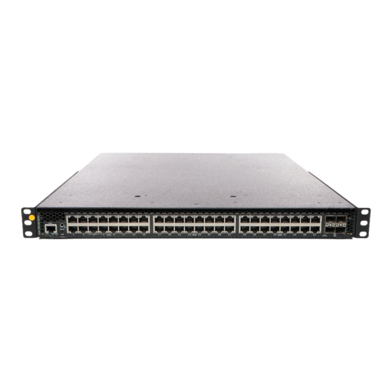
Introduction SSA-G8018-0652 The SSA-G8018-0652 has forty-eight 1000BASE-X SFP ports and four 10GBASE-X SFP+ ports, as shown in Figure Figure 2: SSA-G8018-0652 I/O Port Panel 1 = COM port 5 = 10GBASE-X SFP+ ports 2 = System LEDs 6 = Mounting ears... -
Page 10: Fans
Management You can manage the SSA switch either in-band or out-of-band. In-band remote management is possible using the Extreme Networks’ Extreme Management Center application or the command line interface (CLI) via Telnet. Out-of-band management is provided through the RJ45 COM (Communication) port on the front panel using a PC, a VT terminal, or a VT terminal emulator. -
Page 11: Chapter 2: Installation
I/O ports with your fingers. Advertencia: Para evitar posibles lesiones durante la instalación de su producto interruptor Extreme Networks, evite tocar con los dedos los bordes de los puertos de entrada/salida. Warnhinweis: Verletzungsgefahr beim Installieren des Extreme Networks Switch – berühren Sie die Ränder der E/A-Anschlüsse nicht mit den Fingern. -
Page 12: Installation Site Requirements
Installation Installation Site Requirements Depending upon the cabling used, you need to provide 7.5 to 10 cm (3 to 4 in.) of clearance on the switch I/O port side of the SSA switch. Environmental Guidelines for ExtremeSwitching Products for environmental guidelines relating to the SSA switch installation. -
Page 13: Mounting The Ssa Switch
Installation Mounting the SSA Switch Note The SSA switch comes with integrated mounting ears that are adequate for most installations. For slide-in mounting, high vibration, or high shock installations, an optional rack mount kit (SSA-FB-MOUNTKIT) is available. To install the SSA switch in a rack using the optional rack mount kit, follow the pre-installation discussion here –... - Page 14 Installation Power Supply Airflow and Switch Fan Module Airflow The power supply module has its own fan for cooling the power supply, and each of the two switch fan modules has two fans for cooling the switch circuitry. The airflow direction of all three modules must agree in order to properly cool the installed SSA system.
- Page 15 Installation Reversing the Fan Module Airflow If the SSA switch rack configuration requires the airflow to be from the power supply side to the I/O port side, you must reverse the airflow in the switch fan modules for both switch fan module 1 and switch fan module 2.
- Page 16 Installation When the fan unit is reversed, a metal plate covers the fan unit (as shown in Figure 5 on page 16). To reverse the fan module airflow, follow these steps: Hold the module in your hand. 2 Apply pressure to the edges of the fan units closer to the fan module connector to rotate the fan unit (thick black arrows in Figure 3 Flip the fan unit 180 degrees until the airflow indicator is again completely visible and pointing away...
- Page 17 Installation Rack Mount Ear Positioning If you are installing the SSA switch using the SSA-FB-MOUNTKIT optional rack mount kit, proceed to Optional Rack Mount Rail Kit Installation on page 52. When shipped from the factory, the SSA switch has rack mount ears attached to the edge of the side of the switch containing the I/O ports in a flush mount configuration, as shown in callout 1, Figure 3 page 13.
- Page 18 Installation 4 Repeat step through step on the other side of the chassis. Figure 6: Flush Mount Power Supply Front Configuration 1 = Ear mount screw removal 4 = Ear mount screw insertion 2 = Rack mount ear pivot screw 5 = Pivot screw retightened 3 = Repositioning of rack mount ear Mid-Mount Configuration with I/O Ports Facing Front...
- Page 19 Installation 4 Repeat step through step on the other side of the chassis. Figure 7: Mid-Mount I/O Ports Facing Front Configuration 1 = Ear mount screw removal 3 = Ear mount screw insertion 2 = Repositioning of rack mount ear Mid-Mount Configuration with Power Supply Facing Front The mid-mount, power supply facing front, configuration is depicted in callout 4, Figure 3...
- Page 20 Installation 4 Repeat step through step on the other side of the chassis. Figure 8: Mid-Mount Power Supply Front Configuration 1 = Ear mount screw removal 3 = Ear mount screw insertion 2 = Repositioning of rack mount ear Securing the SSA Switch to the Rack Warning Before rack-mounting the device, ensure that the rack can support it without compromising stability.
- Page 21 Installation Note • The rack mounting ear provides three holes for securing the SSA switch to the rack. Use at least two screws or fasteners appropriate to your rack on each side when securing the SSA switch to the rack. •...
-
Page 22: Unpacking The Power Supplies
Installation Figure 10: Securing the SSA Switch to the Rack in a Mid-Mount Configuration 1 = 4 to 6 screws or fasteners appropriate to the rack You can now unpack and install the SSA power supplies. See Unpacking the Power Supplies on page Installing the SSA Switch on a Flat Surface For flat surface installation, optionally attach the adhesive rubber feet to the bottom of the SSA switch. -
Page 23: Installing The Power Supplies
Installation 2 Verify the contents of the box using Table 3 Remove the power supply from its protective plastic bag. 4 Examine the power supply carefully, checking for damage. If there are any signs of damage, do not install the power supply; instead, contact us Table 6: Contents of SSA Power Supply Carton Item... - Page 24 Installation Figure 11: Installing a Power Supply 1 = Lock Tab 5 If you are installing a second power supply, remove the coverplate from the right power supply bay by unscrewing the screw that attaches the coverplate to the SSA switch and rotating the coverplate S-Series Stand Alone (SSA) Switch Hardware Installation Guide...
-
Page 25: Powering Up The Ssa Switch
Installation out of its position from right to left before disengaging it from the chassis (see Figure 12). Reinstall the screw after the cover plate is removed. Figure 12: Removing the Power Supply Bay Coverplate 1 = Coverplate 2 = Coverplate screw Keep the coverplate in case you need to revert to a single power supply configuration. -
Page 26: Installing The Power Cord Retention Clip Assembly
Installation When the initialization process is successful, the CPU LED turns green. If the CPU LED does not turn green, refer to Troubleshooting on page 34. Installing the Power Cord Retention Clip Assembly The SSA switch comes with two optional power cord retention clip assemblies. Power cord retention clips provide added security against the inadvertent removal of the power cord from the power supply AC receptacle. -
Page 27: Connecting Your Ssa Switch To The Network
Installation Connecting Your SSA Switch to the Network This section provides the procedures for connecting Category 6 unshielded twisted pair (UTP) segments or SFP or SFP+ pluggable transceivers from the network or other devices to the SSA switch. Note If the SSA switch is being installed in a network using Link Aggregation, there are rules concerning the network cable and port configurations that must be followed for Link Aggregation to operate properly. - Page 28 Installation Matrices. You can also refer to the datasheet located at: http://www.extremenetworks.com/product/ transceivers/. To install and remove pluggable transceivers, refer to the following topics: • Preparing to Install a Pluggable Transceiver on page 28 • Installing a Pluggable Transceiver on page 29 •...
- Page 29 Installation Figure 14: SSA Switch Ground Receptacle 1 = Ground receptacle 2 Remove the pluggable transceiver from the anti-static packaging. If there is a protective dust cover on the pluggable transceiver, do not remove it at this time. Installing a Pluggable Transceiver To install an SFP or SFP+ pluggable transceiver in your SSA switch, follow these steps: Hold the pluggable transceiver so that the connector will seat properly.
-
Page 30: Connecting Two Ssa Chassis For Virtual Switch Bonding
Installation Put on the antistatic wrist strap and attach it to the ground receptacle on the switch I/O port side of the SSA switch. Refer to the instructions in the anti-static wrist strap package. See Figure 14 on page 29 for the location of the ground receptacle. -
Page 31: Connecting To A Vt Series Terminal
Installation Connecting to a PC or Laptop To connect a PC or laptop running VT terminal emulation to the SSA switch, follow these steps: Connect the RJ45 connector at one end of the cable to the COM port on the SSA switch. 2 Plug the RJ45 connector at the other end of the cable into an RJ45-to-DB9 adapter. -
Page 32: Completing The Installation
Installation Table 9: COM Port Adapter Wiring and Signal Diagram RJ45 Conductor Signal Blue Receive (RX) Transmit (TX) Green Ground (GRD) Orange Request to Send (RTS) Yellow Clear to Send (CTS) Table 10: VT Series Port Adapter Wiring and Signal Diagram RJ45 DB25 Conductor... - Page 33 San Jose, CA 95134 USA Phone: +1 800 998 2408 E-mail: support@extremenetworks.com WWW: http://www.extremenetworks.com (c) Copyright Extreme Networks, Inc. 2016 Chassis Serial Number: xxxxxxxxxxxx Chassis Firmware Revision: xx.xx.xx.xxxxT User admin last logged in WED SEP 14 16:12:42 2016 There have been 0 failed login attempts since then SSA(su)->...
-
Page 34: Chapter 3: Troubleshooting
Troubleshooting LEDs Troubleshooting Checklist Replacing the SSA Fan Module Removing a Power Supply Shutting Down the SSA Switch Using the OFFLINE/RESET Button Use the topics in this chapter to perform basic troubleshooting for your SSA switch, to replace power supplies and fans, and to shut down the equipment. LEDs The SSA switch has port, system, and power supply LEDs. -
Page 35: System Leds
Troubleshooting Figure 16: SFP and SFP+ Port LEDS 1 = RX LED for bottom port 3 = TX LED for bottom port 2 = RX LED for top port 4 = TX LED for top port Note Figure 16 on page 35 shows SFP ports. The LEDs are the same for both SFP and SFP+ ports. Table 11 describes the LED indications for the RX and TX LEDs for the RJ45, SFP, and SFP+ ports and provides recommended actions. - Page 36 Troubleshooting Figure 17: SSA switch System LEDs Table 12 describes the LED indications for the system LEDs and provides recommended actions. Table 12: System LEDs Color State Recommended Action FAN 1 and 2 Fans are off or booting up. None Green All fans are operating normally.
- Page 37 Troubleshooting Table 12: System LEDs (continued) Color State Recommended Action Blue Blinking: Virtual Switch Bonding is enabled, but None the devices are not bonded Solid: Virtual Switch Bonding is enabled, and the None devices are bonded. The SSA switch is not receiving power from the Ensure that the power cords are power supplies.
-
Page 38: Troubleshooting Checklist
Troubleshooting Table 14: Power Supply LED Status Definitions LED Color Status Green Sufficient power is available to the system. No AC power to the power supply or power supply malfunctioning. Troubleshooting Checklist If the SSA switch is not working properly, refer to Table 15 for a checklist of problems, possible causes, and recommended actions to resolve the problem. -
Page 39: Replacing The Ssa Fan Module
Troubleshooting Table 15: Troubleshooting Checklist (continued) Problem Possible Cause Recommended Action One or more ports Loop condition detected. Verify that Spanning Tree is enabled. Refer to the go into standby for K-, and 7100 Series Configuration Guide no apparent reason instructions to set the type of STP. -
Page 40: Removing A Power Supply
Troubleshooting Determine the location of the failed module using the label shown in Figure Figure 18: Removing the Fan Module 1 = Fan module screws 2 = Fan module location label 2 Unscrew the two captive screws of the failed fan module as shown in Figure 3 Following the discussion in Power Supply Airflow and Switch Fan Module Airflow... - Page 41 Troubleshooting Use appropriate antistatic protection when handling power supplies. 2 If a power cord retention clip is securing the power cord, push down on the retention clip clamp tab to open the clamp and disengage the power cord from the clamp. 3 Unplug the associated power cord from the AC inlet.
-
Page 42: Shutting Down The Ssa Switch Using The Offline/Reset Button
Troubleshooting Shutting Down the SSA Switch Using the OFFLINE/RESET Button You can shut down your SSA switch using the OFFLINE/RESET button, shown in Figure 20 on page 42, which is slightly recessed behind the SSA switch faceplate. There are two procedures for shutting down an SSA switch: •... - Page 43 Troubleshooting If at all possible, use the process described in Recommended Shutdown Procedure on page 42 to shut down your SSA switch. To reset an SSA switch without it performing an orderly shutdown routine, press and hold the OFFLINE/ RESET button for approximately six seconds. S-Series Stand Alone (SSA) Switch Hardware Installation Guide...
-
Page 44: Appendix A: Specifications
The following topics detail the specifications, environmental requirements, and physical properties for your equipment. Extreme Networks reserves the right to change specifications at any time without notice. SSA Switch Specifications The following tables describe I/O ports, physical, electrical, and environmental specifications for the SSA switch. -
Page 45: Pluggable Transceiver Specifications
Specifications Table 20: Environmental Characteristics Operating Temperature 5°C to 40°C (41°F to 104°F) Storage Temperature -30°C to 73°C (-22°F to 164°F) Operating Relative Humidity 5% to 95% (non-condensing) Pluggable Transceiver Specifications For SFP and SFP+ transceiver specifications, refer to the datasheet at: http:// www.extremenetworks.com/product/transceivers/. - Page 46 Specifications Table 22: Compliance Standards Regulatory Compliance Standard Safety UL 60950-1, FDA 21 CFR 1040.10 and 1040.11, CAN/CSA C22.2 No. 60950-1, EN 60950-1, EN 60825-1, EN 60825-2, IEC 60950-1, 2006/95/EC (Low Voltage Directive) Electromagnetic Compatibility (EMC) FCC 47 CFR Part 15 (Class A), ICES-003 (Class A), EN 55022 (Class A), EN 55024, EN 61000-3-2, EN 61000-3-3, AS/NZS CISPR-22 (Class A).
-
Page 47: Appendix B: Clearing Persistent Storage Or Resetting The System Password
To clear the SSA switch persistent storage or to reset the system password to its factory default value, follow these steps: With the console port connected, power up the device. The following message displays: Boot ROM Initialization, Version 01.00.02 Copyright (c) 2016 Extreme Networks, Inc. SDRAM size: 1024 MB Testing SDRAM..PASSED. Loading Boot Image: 0x.00.yy... -
Page 48: Clearing The System Storage Or Resetting The Password Using The Mode Switches
Clearing Persistent Storage or Resetting the System Password 3 Enter the clearpw command to clear the system password only, or enter clearnvram to clear all of persistent storage. [System Image Loader]: clearpw [System Image Loader]: [System Image Loader]: clearnvram [System Image Loader]: 4 Power the system off and back on to reboot the system using the factory defaults. - Page 49 Clearing Persistent Storage or Resetting the System Password Warning This unit may have more than one power supply cord. Disconnect two power supply cords before servicing to avoid electric shock. Advertencia: Esta unida puede tener mas de un cable de fuente de poder. Desconectar dos cables de fuentes de poder antes de dar servicio para prevenir riesgo eléctrico.
-
Page 50: Setting The Mode Switches
Clearing Persistent Storage or Resetting the System Password • Switches 1– 6: For Extreme Networks use only. • Switch 7: Clear Persistent Data. Changing the position of this switch from the up position to the down position clears persistent data on the next power-up of the SSA switch. All user-entered parameters, such as the IP address, system name, and so on, are reset to the factory default settings. - Page 51 Clearing Persistent Storage or Resetting the System Password 5 Reinstall fan module 2 as described in step on page 40 through step on page 40. Note Switches 7 and 8 are treated as one-time toggle switches. The system looks for a change in position since the last system reset.
-
Page 52: Appendix C: Optional Rack Mount Rail Kit Installation
Optional Rack Mount Rail Kit Installation Required Tools Installation Site Requirements Contents of the Mounting Kit Removing the Rack Mount Ears from the SSA Switch Installing the Adapter Plates Four-Post Rack Mount Installation Two-Post Rack Mount Installation This appendix describes the installation and use of the optional SSA Universal Rack Mount kit, model number SSA-FB-MOUNTKIT. -
Page 53: Installation Site Requirements
Optional Rack Mount Rail Kit Installation Installation Site Requirements If you plan to cable your SSA switch with SFP+ pluggable transceivers, you might need to have 7.5 cm to 10 cm (3 to 4 in.) of clearance on the switch I/O port side of the SSA switch. Environmental Guidelines for ExtremeSwitching Products for environmental guidelines relating to the installation. -
Page 54: Removing The Rack Mount Ears From The Ssa Switch
Optional Rack Mount Rail Kit Installation Table 23: Contents of SSA-FB-MOUNTKIT (continued) Item Quantity 10-32 pan head screws (black) 10-32 cage nuts Note The SSA-FB-MOUNTKIT mounting kit does not include rack screws. You must provide screws or fasteners appropriate to your rack for securing the rails and the SSA chassis in the equipment rack. - Page 55 Optional Rack Mount Rail Kit Installation • The rail and mid-bracket assemblies used in the two-post rack configuration (see Two-Post Rack Mount Installation on page 59). The adapter plates can be installed in either a flush or a recessed configuration of up to 3.8 cm (1.5 in.). The SSA switch can be configured for air intake on either the chassis switch I /O port side or the power supply side.
-
Page 56: Four-Post Rack Mount Installation
Optional Rack Mount Rail Kit Installation 2 Align either the flush mount adapter plate screw holes (Callout 2) or the appropriate recess mount adapter plate screw holes with the three chassis screw holes on each side of the chassis. Callout 3 identifies the screw holes used to recess the chassis by .5, 1.0, or 1.5 inches. Note When recess mounting, use care that the installation does not result in openings above and below the chassis face at the inlet side that allow for hot air recirculation from the... - Page 57 Optional Rack Mount Rail Kit Installation 2 = Flush mount, power supply side to switch I/O port 5 = Airflow direction side airflow 3 = Cool air intake side This section details the installation of the optional rack mount kit for a four-post rack and covers installing: •...
- Page 58 Optional Rack Mount Rail Kit Installation Adjust the length of the two assemblies (callout 1) to agree with the distance between the outer face of the vertical rack posts. The screws (callout 5) holding the assembly together may need to be loosened slightly to allow for the adjustment.
-
Page 59: Two-Post Rack Mount Installation
Optional Rack Mount Rail Kit Installation 3 Secure the chassis with one screw or fastener appropriate to your rack in each of two adapter plate ear screw holes. A flange (callout 6) toward the back of each rail assembly secures the back side of the chassis adapter plate in place. - Page 60 Optional Rack Mount Rail Kit Installation 4 = Mid-mount, power supply to I/O port side airflow This section details the installation of the optional rack mount kit for a two-post rack, including: • Preparing the rack mount rail assembly for a two-post rack installation, by removing the extension from the rail assembly and adding a mid-bracket to the rail •...
- Page 61 Optional Rack Mount Rail Kit Installation Attaching the Mid-Bracket to the Rail Note The rack post must have holes on both the front and rear flanges to properly secure the rack mount rail in either a 3-inch or 7.25-inch flush two-post rack configuration. The rack post must have holes on the front flange to secure the rack mount rail in a mid-mount two-post rack configuration.
- Page 62 Optional Rack Mount Rail Kit Installation Figure 29: Securing the Mid-Bracket to the Rail (3-Inch Flush Mount) 1 = Four screws from extension rack assembly 3 = Rail ear 2 = Mid-bracket 2 Insert and secure the four screws (callout 1) from the rack mount extension assembly for both rails. Securing the Mid-Bracket (7.25-Inch Flush Mount or Mid-Mount Assembly) Secure the mid-bracket to the rail for a 7.25-inch post flush mount or mid-mount assembly as shown in the following illustrations.
- Page 63 Optional Rack Mount Rail Kit Installation 1 = Four screws from extension rack assembly 2 = Mid-bracket Figure 31: Securing the Mid-Bracket to the Rail (7.25-Inch Mid-Mount) 1 = Four screws from extension rack assembly 3 = Rail ear square opening 2 = Mid-bracket 4 = Cage nut To secure the mid-bracket, follow these steps:...
- Page 64 Optional Rack Mount Rail Kit Installation Figure 32: Securing a Flush Mount Rail Assembly 1 = Rack-appropriate screws of fasteners (8) 2 Secure each rail assembly with two screws or fasteners appropriate to the rack at both the rail ear and mid-bracket ear.
- Page 65 Optional Rack Mount Rail Kit Installation Figure 33: Securing Mid-Mount Rail Assembly 1 = Rack appropriate screws or fasteners (4) 3 = Cage nuts (2) 2 = Rail ear square opening 3 Secure the rail assembly with two screws or fasteners appropriate to the rack at both the rail ear and mid-bracket ear.
- Page 66 Optional Rack Mount Rail Kit Installation Figure 34: Securing the SSA switch to the Rack 1 = Flush mount configuration 3 = Rack-appropriate screws or fasteners (2) 2 = Mid-mount configuration 4 = Black 10-32 screws (2) 2 For a flush mount rail assembly configuration, secure each side of the chassis using a user-supplied screw or fastener appropriate to your rack.
-
Page 67: Appendix D: Installing The Ssa-Wall-Mount Kit
Installing the SSA-WALL-MOUNT Required Tools Installation Site Requirements Contents of the SSA-WALL-MOUNT Kit Preparing the Installation Site Mounting the SSA Chassis on a Wall This appendix provides instructions for installing the SSA on a wall using the optional SSA-WALL- MOUNT kit. Warning Electrical hazard: Only qualified personnel should perform installation procedures. -
Page 68: Preparing The Installation Site
Installing the SSA-WALL-MOUNT Kit Table 24: Contents of SSA-WALL-MOUNT Kit Item Quantity Mounting bracket 10-32 x .5 inch pan head screws Note The SSA-WALL-MOUNT kit does not include hardware for installing the mounting bracket on a wall. You must provide screws and wall anchors that are appropriate for the wall on which you are installing the mounting bracket. - Page 69 Installing the SSA-WALL-MOUNT Kit Typical drill size is ½ inch for the 3/16 inch toggle bolt. Follow the manufacturer’s instructions. Reusable Anchors The minimum recommended size for reusable anchors is #10 size minimum. Each of the four reusable anchors must be rated for 14.6 kg (32.2 lb.) minimum and be the appropriate size for the sheathing thickness.
-
Page 70: Mounting The Ssa Chassis On A Wall
Installing the SSA-WALL-MOUNT Kit Use sizes that support a #10 screw minimum. Typical drill size is 5/16 inch for the #10 conical lead anchor for concrete. Typical drill size is ¼ inch for the #10 flanged polypropylene anchor for concrete. Follow the manufacturer’s instructions, including the recommendation for drill depth for the insert that you are using. - Page 71 Installing the SSA-WALL-MOUNT Kit 1 = Customer-supplied screws 2 Open the gate on the top side of the mounting bracket as shown in Figure 36 on page 71. a Pull the right and left plungers simultaneously to unlock the gate. To lock the plungers in the open position, rotate the opened plungers counter-clockwise.
- Page 72 Installing the SSA-WALL-MOUNT Kit Figure 37: Mounting Bracket Gate in the Open Position S-Series Stand Alone (SSA) Switch Hardware Installation Guide...
- Page 73 Installing the SSA-WALL-MOUNT Kit 3 Holding the SSA switch with the I/O connectors facing left, slide the bottom side of the SSA chassis under the lip on the bottom side of the mounting bracket. Figure Note You must install the SSA chassis in the orientation shown in Figure 38: I/O connectors facing left, top of the SSA switch facing out.
- Page 74 Installing the SSA-WALL-MOUNT Kit Figure 39: Closing the Gate 1 = Gate S-Series Stand Alone (SSA) Switch Hardware Installation Guide...
- Page 75 Installing the SSA-WALL-MOUNT Kit 6 Using the 10-32 screws included with the mounting bracket, secure the front of the SSA chassis to the left of the mounting bracket. Figure Figure 40: Securing the SSA Chassis to the Mounting Bracket You can now cable the I/O ports and power up the SSA chassis as described in Installation on page 11.
-
Page 76: Appendix E: Regulatory Compliance
Regulatory Compliance Safety Information Declaration of Conformity Warning Electrical hazard: Only qualified personnel should perform installation procedures. Riesgo Electrico: Solamente personal calificado debe realizar procedimientos de instalacion. Elektrischer Gefahrenhinweis: Installationen sollten nur durch ausgebildetes und qualifiziertes Personal vorgenommen werden. Risques d'électrocution: Seul un personnel qualifié doit effectuer les procédures d'installation. Federal Communications Commission (FCC) Notice This device complies with Part 15 of the FCC rules. - Page 77 Regulatory Compliance Class A ITE Notice Warning This is a Class A product. In a domestic environment this product may cause radio interference in which case the user may be required to take adequate measures. Clase A. Aviso de ITE Warning Advertencia: Este es un producto de Clase A.
-
Page 78: Hazardous Substances
Regulatory Compliance AS/NZS CISPR 22 Hazardous Substances This product complies with the requirements of Directive 2011/65/EU of the European Parliament and of the Council of 8 June 2011 on the restriction of the use of certain hazardous substances in electrical and electronic equipment. -
Page 79: Safety Information
Regulatory Compliance Battery Notice This product contains a battery used to maintain product information. If the battery should need replacement it must be replaced by Service Personnel. Contact Technical Support for assistance. Caution There is an explosion risk if you replace the battery with the incorrect type. Dispose of expended battery in accordance with local disposal regulations. - Page 80 Regulatory Compliance Class 1 Laser Transceivers The single mode interface modules use Class 1 laser transceivers. Read the following safety information before installing or operating these modules. The Class 1 laser transceivers use an optical feedback loop to maintain Class 1 operation limits. This control loop eliminates the need for maintenance checks or adjustments.
-
Page 81: Declaration Of Conformity
Niemals direkt auf den Faser-TX-Anschluß und auf die Faserkabelenden schauen, während diese eingeschaltet sind. Declaration of Conformity Application of Council 2004/108/EC Directive(s): 2006/95/EC Manufacturer’s Name: Extreme Networks, Inc. Manufacturer’s Address: 145 Rio Robles San Jose, CA 95134 European Representative Name: Extreme Networks European Representative Nexus House... - Page 82 Regulatory Compliance Conformance to Directive(s)/ EC Directive 2004/108/EC Product Standards: EN55022:2006 A1:2007 EN 55024:1998 A1:2001 A2:2003 EN 61000-3-2:2006 A1:2009 A2:2009 EN 61000-3-3:2008 EC Directive 2006/95/EC EN 60950-1:2006 A1:2009 EN 60825-1:2007 EN 60825-2:2004 A1:2007 EC Directive 2011/65/EU Equipment Type/Environment: Information Technology Equipment, for use in a Commercial or Light Industrial Environment.
-
Page 83: Index
Index features SSA-G8018-0652 9 adapter plates SSA-T8028-0652 8 installing 54 flat-surface installation 22 airflow reversing 15, 16 selecting direction 14 I/O ports mid-mount configuration 18 installing boot loader final steps 32 for resetting system 47 on a wall 68–70 checklist LEDs troubleshooting 38 port 34, 38 clearing persistent storage 47, 48, 50 power supply 37 COM port system 35... - Page 84 Index pluggable transceivers SSA switch (continued) connecting 27, 29 specifications 44 preparing to connect 28 SSA Universal Rack Mount kit removing 29 contents 53 specifications 45 for four-post rack 56–58 ports for two-post rack 59–65 connecting to network 27 installing adapter plates 54 LEDs 34 site requirements 53 management 30 tools required 52 management (COM) 45 SSA-WALL-MOUNT kit power connection 25 contents 67...
Need help?
Do you have a question about the SSA-G8018-0652 and is the answer not in the manual?
Questions and answers