
Related Manuals for Extreme Networks ExtremeSwitching SLX 9250


Summary of Contents for Extreme Networks ExtremeSwitching SLX 9250
- Page 1 ExtremeSwitching SLX 9250 Hardware Installation Guide 9036437-00 Rev AD October 2020...
- Page 2 Copyright © 2020 Extreme Networks, Inc. All rights reserved. Legal Notice Extreme Networks, Inc. reserves the right to make changes in specifications and other information contained in this document and its website without prior notice. The reader should in all cases consult representatives of Extreme Networks to determine whether any such changes have been made.
-
Page 3: Table Of Contents
Grounding the Rack............................24 Securing the Rack.............................24 Evaluating and Meeting Cable Requirements....................25 Labeling Cables and Keeping Accurate Records................25 Installing Cable..............................26 Using RJ45 Connector Jackets........................31 Preventing Radio Frequency Interference (RFI)................32 Meeting Power Requirements..........................32 ExtremeSwitching SLX 9250 Hardware Installation Guide... - Page 4 Removing and Replacing Components......................65 Replacing Internal Power Supplies......................65 Replacing Fan Modules..........................65 Removing the Switch from the Rack...................... 66 ExtremeSwitching SLX 9250 Technical Specifications..........70 System specifications..............................70 SLX 9250 Software Specifications........................70 Weights and Physical Dimensions........................71 Acoustic Specifications ............................73 Fan Tray and Speed Variation..........................73...
- Page 5 Federal Communications Commission (FCC) Notice................88 Germany statement..............................88 KCC statement (Republic of Korea)......................... 88 Japan (VCCI Class A).............................. 89 Japan power cord ..............................89 Cautions and Danger Notices..................90 Cautions..................................90 General cautions............................... 90 Danger Notices................................94 General dangers..............................94 ExtremeSwitching SLX 9250 Hardware Installation Guide...
-
Page 6: Preface
ExtremeSwitching switches or SLX routers, the product is referred to as the switch or the router. Table 1: Notes and warnings Icon Notice type Alerts you to... Helpful tips and notices for using the product. Note Useful information or instructions. Important Important features or instructions. ExtremeSwitching SLX 9250 Hardware Installation Guide... - Page 7 Repeat the previous element, for example, member[member...]. In command examples, the backslash indicates a “soft” line break. When a backslash separates two lines of a command input, enter the entire command at the prompt without the backslash. ExtremeSwitching SLX 9250 Hardware Installation Guide...
-
Page 8: Documentation And Training
Extreme Optics Compatibility Other resources such as white papers, data sheets, and case studies Extreme Networks offers product training courses, both online and in person, as well as specialized certifications. For details, visit www.extremenetworks.com/education/. Getting Help If you require assistance, contact Extreme Networks using one of the following methods: Extreme Portal Search the GTAC (Global Technical Assistance Center) knowledge base;... -
Page 9: Providing Feedback
4. Select Submit. Providing Feedback The Information Development team at Extreme Networks has made every effort to ensure the accuracy and completeness of this document. We are always striving to improve our documentation and help you work better, so we want to hear from you. We welcome all feedback, but we especially want to know about: •... -
Page 10: About This Document
What is new in this document on page 12 Supported hardware and software The ExtremeSwitching SLX 9250 Series switches offer a versatile and efficient core/aggregation switching functionality for both campus and data center environments. The SLX 9250 Series switches run the SLX-OS operating system. - Page 11 The following table list the supported SLX 9250 Switch Fan assemblies. Table 6: Supported SLX 9250 Switch Fan Assemblies Part number Description Introduced OS Currently supported XN-FAN-001-F Fan unit, Front-to-Back airflow SLX-OS 20.1.1 XN-FAN-001-R Fan unit, Back-to-Front airflow SLX-OS 20.1.1 ExtremeSwitching SLX 9250 Hardware Installation Guide...
-
Page 12: Slx 9250 Switch License Option
SLX 9250 Advanced Feature License for GuestVM, Analytics Path, PTP, BGP-EVPN, For information about licensing option for SLX-OS support for SLX 9250 Switches, reference the Extreme SLX-OS Software Licensing Guide What is new in this document This is a new document. ExtremeSwitching SLX 9250 Hardware Installation Guide... -
Page 13: Device Overview
Device management options on page 16 Hardware features The ExtremeSwitching SLX 9250 Series switches offer a versatile and efficient core/aggregation switching functionality for both campus and data center environments. The SLX 9250 Series switches run on the SLX-OS operating system. -
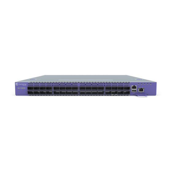
Page 14: Slx 9250-32C Switch Front View
QSFP28/ QSFP+. With a few exceptions, noted below, these ports are configurable for 100 Gb, 40 Gb, 4x25 Gb, and 4x10 Gb modes. For information about QSFP28 and QSFP+ optical modules, ee the Extreme Networks Pluggable Transceivers Installation Guide. •... -
Page 15: Port-Side View Of The Slx 9250 Switch
In 40-gigabit mode, each port can be partitioned into four 10-gigabit data lanes. Logical port numbers are assigned depending on whether the physical ports are partitioned into data lanes. If there is no partitioning/channelizing, the logical port numbers correspond to the physical port ExtremeSwitching SLX 9250 Hardware Installation Guide... -
Page 16: Nonport-Side View Of The Slx 9250 Switch
You can use the management functions built into the device to monitor the port status, physical status, and other information to help you analyze device performance and to accelerate system debugging. The device automatically performs a power-on self-test (POST) each time it is turned on. ExtremeSwitching SLX 9250 Hardware Installation Guide... - Page 17 Ethernet or serial Extreme SLX-OS Management (CLI) connection Configuration Guide REST or NETCONF/YANG Ethernet connection Yes Extreme SLX-OS Management APIs. Configuration Guide Standard SNMP applications Ethernet or serial Extreme SLX-OS Management connection Configuration Guide ExtremeSwitching SLX 9250 Hardware Installation Guide...
-
Page 18: Power Supplies
You can remove one power supply without interrupting the switch's operation. For more information, see the following topics. • 750 W AC Power Supply on page 19 ExtremeSwitching SLX 9250 Hardware Installation Guide... -
Page 19: 750 W Ac Power Supply
Note AC power input cords are not provided with AC power supplies. You can order an appropriate cord from Extreme Networks or from your local supplier. The power cord must meet the requirements listed in Power Cord Requirements for AC-Powered Switches and AC Power... -
Page 20: Preparing For The Installation
34 Preparing for the Installation Before you install your Extreme Networks equipment, careful planning can help ensure that it is used effectively and help prepare you for future growth. Only qualified service personnel should install, maintain, or remove a switch, chassis, or its components. -
Page 21: Operating Environment Requirements
Northbrook, IL 60062 wiring and equipment to determine whether they meet certain safety standards when properly used. Acceptance is usually indicated by the words “UL Approved” or “UL Listed.” ExtremeSwitching SLX 9250 Hardware Installation Guide... -
Page 22: Setting Up The Wiring Closet
We recommend that you consult an electrical contractor for commercial building and wiring specifications. Controlling the Temperature Extreme Networks equipment generates a significant amount of heat. It is essential that you provide a temperature-controlled environment for both performance and safety. ExtremeSwitching SLX 9250 Hardware Installation Guide... -
Page 23: Controlling The Humidity Level
Alternately, you can restart the system immediately by removing and then restoring all line power to the system. Safeguards are built into all Extreme Networks switches and power supply units to minimize the risk of fire. Controlling the Humidity Level To maximize equipment life, keep operating humidity between 50% and 70% relative humidity (non- condensing) during typical operation. -
Page 24: Rack Specifications And Recommendations
This will ensure good grounding between the chassis, rack, and earth ground. Note Because building codes vary worldwide, Extreme Networks strongly recommends that you consult an electrical contractor to ensure proper equipment grounding for your specific installation. -
Page 25: Evaluating And Meeting Cable Requirements
Assign a unique block of sequential numbers to the group of cables that run between each pair of wiring closets. • Assign a unique identification number to each equipment rack. • Identify all wiring closets by labeling the front panel of your Extreme Networks equipment and other hardware. ExtremeSwitching SLX 9250 Hardware Installation Guide... -
Page 26: Installing Cable
Before connecting any category 5 UTP cable to the switch, discharge ESD from the cable by plugging the RJ45 connector into a LAN static discharge device or use an equivalent method. ExtremeSwitching SLX 9250 Hardware Installation Guide... - Page 27 Every cable has a minimum bend radius, example, and fibers will be damaged if the cables are bent too sharply. It is also important not to stretch the cable during installation. Extreme Networks recommends ExtremeSwitching SLX 9250 Hardware Installation Guide...
- Page 28 Cable Distances and Types below shows one example of cable media types and maximum distances that support reliable transmission in accordance with international standards (except where noted). Refer to Extreme Networks Pluggable Transceivers Installation Guide for descriptions of optics and cables, as well as a complete list of supported cable lengths.
- Page 29 10BASE-T Category 3 and higher UTP cable – 1 Proprietary to Extreme Networks. Connections between two Extreme Networks 1000BASE-LX interfaces that use 10/125 µm single-mode fiber can use a maximum distance of 10,000 meters. ExtremeSwitching SLX 9250 Hardware Installation Guide...
- Page 30 Installing Cable Preparing for the Installation The following tables below list the Extreme Networks 100Gb Direct-Attach Cables and the Extreme Networks 40Gb Direct-Attach Cables Table 14: Extreme Networks 100Gb Direct-Attach Cables Cable Type Part Number Length QSFP28-QSFP28 Direct attach passive copper cable 10411 or AA1405029-...
-
Page 31: Using Rj45 Connector Jackets
31 shows examples of recommended and non-recommended connector jacket types. 2 Proprietary to Extreme Networks. Connections between two Extreme Networks 1000BASE-LX interfaces that use 10/125 µm single-mode fiber can use a maximum distance of 10,000 meters. ExtremeSwitching SLX 9250 Hardware Installation Guide... -
Page 32: Preventing Radio Frequency Interference (Rfi)
Routing UTP cable near electrical transformers In areas or applications where these situations cannot be avoided, use fiber optic cabling or shielded twisted pair cabling. Meeting Power Requirements Observe the following requirements and precautions for powering your hardware. ExtremeSwitching SLX 9250 Hardware Installation Guide... -
Page 33: Power Supply Requirements
Extreme Networks equipment. The web page provides specifications for power cords in each country so that you can purchase cords locally. UPS (Uninterruptible Power Supply) Requirements... -
Page 34: Following Applicable Industry Standards
UPS transfer time. UPS transition times vary between UPS models and implementations, but shorter transition times are preferred. For Extreme Networks stacking products, we recommend a UPS transition time of 20 milliseconds or less to ensure optimum performance and minimize service interruptions. - Page 35 For more information, see the following ANSI/TIA/EIA standards: • ANSI/TIA/EIA-568-A—the six subsystems of a structured cabling system • ANSI/TIA/EIA-569-A—design considerations • ANSI/TIA/EIA-606—cabling system administration • ANSI/TIA/EIA-607—commercial building grounding and bonding requirements You can access these standards at: www.ansi.org or www.tiaonline.org. ExtremeSwitching SLX 9250 Hardware Installation Guide...
-
Page 36: Installing Your Switch
57 Connecting Network Interface Cables on page 57 Installing Your Switch Before you attempt to install or remove an Extreme Networks switch, read the precautions in Safety Considerations for Installing Switches on page 37. Extreme Networks switches fit into standard 19-inch equipment racks. -
Page 37: Safety Considerations For Installing Switches
20 and ensure that you have the appropriate people and tools on hand. Installing Extreme Networks switches is easiest when there are two people to maneuver the switch and attach mounting hardware. Provide enough space in front of and behind the switch so that you can service it easily. Allow a minimum of 122 cm (48 in) in front of the rack and 76 cm (30 in) behind the rack. -
Page 38: Attaching The Switch To A Rack
43 Note • When you install Extreme Networks switches, we recommend that you have two people to maneuver the switch and the mounting hardware. • Take care to load the rack so that it is not top-heavy. Start installing equipment at the bottom and work up. - Page 39 One Side of the Switch Housing Figure 8: Attaching a Mounting Bracket to One Side of the Switch Housing 5. Repeat step 4 to attach the other mounting bracket to the other side of the housing. ExtremeSwitching SLX 9250 Hardware Installation Guide...
- Page 40 See the figure Attaching the Slider Assembly to the Front Rack Post . Figure 9: Attaching the Slider Assembly to the Front Rack Post b. Extend the slider assembly until its rear clamp fits around the rear rack post. ExtremeSwitching SLX 9250 Hardware Installation Guide...
- Page 41 See Figure Extending the Slider Assembly to Fit the Rack. Figure 11: Extending the Slider Assembly to Fit the Rack The sliding rails remain attached to the slider assembly. 9. Screw the mounting ear thumbscrews into the rack rails to hand tightness. ExtremeSwitching SLX 9250 Hardware Installation Guide...
- Page 42 12. Release the tabs on both slider assemblies, and slide the switch back until it is firmly in place. Screw the mounting ear thumbscrews into the rack rails to hand tightness. See the Figure Pushing the Mounting Brackets into the Rail Assemblies. Figure 13: Pushing the Mounting Brackets into the Rail Assemblies ExtremeSwitching SLX 9250 Hardware Installation Guide...
-
Page 43: Attaching The Switch To A Two-Post Rack
The side of the switch has different sets of holes for attaching mounting brackets in either configuration. Brackets for a two-post mount are not included in the box with your switch. However, they can be ordered separately using part number XN-2P-RKMT299. ExtremeSwitching SLX 9250 Hardware Installation Guide... - Page 44 For a front mount, position the bracket over the holes so that the flange (ear) is even with the front of the switch, as shown in the figure below: Attaching a Short Mounting Bracket (Ear): Front of Switch . Figure 15: Attaching a Short Mounting Bracket (Ear): Front of Switch ExtremeSwitching SLX 9250 Hardware Installation Guide...
- Page 45 Position the long bracket over the holes between the front and the middle of the switch. Orient it so that its flange (ear) rests against the rack post. See the diagrams below: Attaching a Long Mounting Bracket: Front of Switch and Attaching a Long Mounting Bracket: Middle of Switch. ExtremeSwitching SLX 9250 Hardware Installation Guide...
- Page 46 Attaching the Switch to a Two-Post Rack Installing Your Switch Figure 17: Attaching a Long Mounting Bracket: Front of Switch Figure 18: Attaching a Long Mounting Bracket: Middle of Switch ExtremeSwitching SLX 9250 Hardware Installation Guide...
- Page 47 6. Secure the flanges (ears) on both sides of the switch to the rack posts, using screws that are appropriate for the rack. (Rack-mounting screws are not provided.) The completed installation is shown in the diagrams below: Two-Post Front Mount: Complete and Two-Post Mid-Mount: Complete. Figure 19: Two-Post Front Mount: Complete ExtremeSwitching SLX 9250 Hardware Installation Guide...
-
Page 48: Installing Optional Components
Extreme Hardware/Software Compatibility and Recommendation Matrices. Pluggable Transceiver Modules Extreme Networks offers several optical transceiver modules for transmitting and receiving data over optical fiber rather than through electrical wires. Install these modules using the instructions in Extreme Networks Pluggable Transceivers Installation Guide. -
Page 49: Optical Cables
Optical Cables Direct-attach copper and fiber cables provide connections between unpopulated SFP+, SFP28, QSFP+, and QSFP28 ports. To install optical cables, refer to the instructions in Extreme Networks Pluggable Transceivers Installation Guide. Breakout cables The copper breakout cables are terminated with optical connectors and are available in 1m, 3m, 5m, or greater lengths. -
Page 50: Installing Internal Power Supplies
2. Verify that the new power supply is right side up. 3. Verify that the new power supply's airflow direction (front-to-back or back-to-front) is compatible with the other installed power supply (if any) and with the installed fan modules. ExtremeSwitching SLX 9250 Hardware Installation Guide... - Page 51 EMI levels. 6. Connect the AC power cord. a. If necessary, slide the plastic cord retainer farther away from the back of the switch. b. Connect the AC power cord to the input connector. ExtremeSwitching SLX 9250 Hardware Installation Guide...
- Page 52 Always make sure that the source outlet is properly grounded before plugging the AC power cord into the AC power supply. To install a second power supply, repeat this procedure. When you are finished, follow the steps in Powering up the Switch on page 57 . ExtremeSwitching SLX 9250 Hardware Installation Guide...
-
Page 53: Installing A 750 W Internal Dc Power Supply
You will need three cable wires for each installed DC power supply: two input cables and a grounding cable. We recommend that each cable have differently colored insulation, as described in Required Tools and Materials for Installing a 750 W DC Power Supply on page 53. ExtremeSwitching SLX 9250 Hardware Installation Guide... - Page 54 6. To install a second power supply, repeat the procedure. When you are finished, connect the ground wire to each power supply. See Connecting the Ground Wire to a 750 W DC Power Supply on page 55. ExtremeSwitching SLX 9250 Hardware Installation Guide...
- Page 55 Connecting a 750 W DC Power Supply to the Source Voltage Two 750 W DC power supplies are available: model XN-DCPWR-750W-F (front-to-back airflow) and model XN-DCPWR-750W-R (back-to-front airflow). Both can connect to a –48 V power source. ExtremeSwitching SLX 9250 Hardware Installation Guide...
- Page 56 5. Connect the cables to the DC source voltage, using hardware appropriate to the installation site and following local and national electrical codes. Power up to the switch, following the steps in Powering up the Switch on page 57. ExtremeSwitching SLX 9250 Hardware Installation Guide...
-
Page 57: Powering Up The Switch
An AC power is not included with the AC power supply. You can purchase AC power cords for use in the US and Canada from Extreme networks or from your local supplier. The cord must meet the requirements listed in... - Page 58 5. Repeat step 1 through step 5 for the remaining cables on this or other switches or I/O modules. 6. Dress and secure the cable bundle to provide appropriate strain relief and protection against bends and kinks. ExtremeSwitching SLX 9250 Hardware Installation Guide...
-
Page 59: Activating And Verifying The Switch
3. Access the device using a terminal emulator application (such as HyperTerminal in a Windows environment or Tip in a LINUX environment). 4. Disable any serial communication programs running on the workstation (such as synchronization programs). ExtremeSwitching SLX 9250 Hardware Installation Guide... -
Page 60: Configuring The Switch For Use
Please ensure the Root and Factory passwords are documented in a secure location. Recovery of a lost Root or Factory password will result in fabric downtime. for user - admin ExtremeSwitching SLX 9250 Hardware Installation Guide... - Page 61 Extreme SLX-OS Security Configuration Guide for the SLX 9250 device. The switch is ready for use. To configure other switch features, see the Extreme SLX-OS Layer 2 Switching Configuration Guide . ExtremeSwitching SLX 9250 Hardware Installation Guide...
-
Page 62: Monitoring The Switch
Table 17: LEDs for Data Ports (1-32) Port Configuration Color/State Meaning 100 Gb Steady green Port OK or 4x25 Gb Blinking green Port transmitting or receiving Slow blinking green Port disabled by software No link/Fault ExtremeSwitching SLX 9250 Hardware Installation Guide... -
Page 63: 750 W Ac Power Supply Leds
The following tables describe the meanings of the LEDs on the 750 W AC power supply (part number XN-ACPWR-750W-F or XN-ACPWR-750W-R). The LEDs are located on the end of the power supply unit, arranged vertically to the left of the power cord receptacle. ExtremeSwitching SLX 9250 Hardware Installation Guide... -
Page 64: 750 W Dc Power Supply Leds
(Solid) No PSU fault OUT OK DC output DC output OK (Green) Good (solid) Off or DC output fail Blinking IN OK DC input DC input OK (Green) Good "IN OK" DC input fail ExtremeSwitching SLX 9250 Hardware Installation Guide... -
Page 65: Removing And Replacing Components
If the switch's fan tray has a red tab, the airflow is front-to-back. Use a fan module labeled Air Out. • If the switch's fan tray has a blue tab, the airflow is back-to-front. Use a fan module labeled Air In. Note The operating-system software cannot display the airflow direction. ExtremeSwitching SLX 9250 Hardware Installation Guide... -
Page 66: Removing The Switch From The Rack
Attaching the Switch to a Four-Post Rack on page 38 • Attaching the Switch to a Two-Post Rack on page 43 1. Disconnect the switch from its power source or sources. 2. Remove all cables and transceivers. ExtremeSwitching SLX 9250 Hardware Installation Guide... - Page 67 Carefully slide the switch out of the slider assembly and place it on a flat surface. You can leave the slider assemblies in place. If you want to remove them, continue with the next step . ExtremeSwitching SLX 9250 Hardware Installation Guide...
- Page 68 On one of the slider assemblies, push the rear clamp until it separates from the rear rack post. See the diagram below - Removing the Slider Assembly: Rear Rack Post. Figure 29: Removing the Slider Assembly: Rear Rack Post ExtremeSwitching SLX 9250 Hardware Installation Guide...
- Page 69 If the switch cannot be tilted (because other equipment is mounted directly above and below), remove one or two mounting brackets from the switch and then slide the switch out. If you plan to use the switch again later, we recommend storing it with the mounting brackets attached. ExtremeSwitching SLX 9250 Hardware Installation Guide...
-
Page 70: Extremeswitching Slx 9250 Technical Specifications
750 W Power Supplies Technical Specifications on page 78 Power Cord Requirements for AC-Powered Switches and AC Power Supplies on page 80 The ExtremeSwitching SLX 9250 Series includes the following switch models: Part number Description SLX9250-32C SLX9250-32C Switch with two empty power supply slots, and six empty fan slots. Supports 32x100/40GE SLX9250-32C-AC-F SLX9250-32C Switch AC with Front to Back Airflow. -
Page 71: Weights And Physical Dimensions
Width: 43.96 cm (17.31 in) Length: 53.95 cm (21.24 in) XN-FAN-001-F: Fan unit, front-to-back or XN-FAN-001-R: Height: 4.0 cm (1.57 in) Fan Unit back-to-front Width: 4.0 cm (1.57 in) Length: 13.4 cm (5.28 in) ExtremeSwitching SLX 9250 Hardware Installation Guide... - Page 72 17 kg (37.40 lb) Fan unit, front-to-back or back-to-front 1.82 kg (4.01 lb) Four-post rack mount kit (included with switch) 2.71 kg (5.97 lb) Two-post rack mount kit (separately orderable) 3.20 kg (7.05 lb) ExtremeSwitching SLX 9250 Hardware Installation Guide...
-
Page 73: Acoustic Specifications
Tray 6 Fan 1 high speed Unknown* Tray 6 Fan 2 medium speed Unknown* * - The color of the tab on the fan tray indicates the airflow direction: • Red = Front-to-Back • Blue = Back-to-Front ExtremeSwitching SLX 9250 Hardware Installation Guide... -
Page 74: Power Options
(BTU/hr) (Fans (Watts) (Fans ports linked) high, all ports high, all ports 100% traffic) 100% traffic) SLX9250-32C-AC-F 734 BTU/ hr 215W 1573 BTU/ hr 461W SLX9250-32C-AC-R 734 BTU/ hr 215W 1573 BTU/ hr 461W ExtremeSwitching SLX 9250 Hardware Installation Guide... -
Page 75: Mean Time Between Failures (Mtbf)
384936 hrs @ 25°C SLX9250-32C-AC-R 444822 hrs @ 25°C CPU, Memory Table 32: CPU, Memory 1GHz 64-bit CPU 16 Gb memory, 128 Gb SSD 4GB eMMC Flash Memory 24 MB buffer for ASIC, per chip ExtremeSwitching SLX 9250 Hardware Installation Guide... -
Page 76: Standards
EN 55032:2015/AC:2016-07 Class A EN 55024:2010/A1:2015 EN 55011:2009+A1:2010 (Group 1, Class A) EN 61000-6-2:2005+AC:2005 EN 61000-6-4:2007+A1:2011 EN 61000-3-2:2014 Class A EN 61000-3-3:2013 EN 61000-4-2:2009 EN 61000-4-3:2006+A1:2008+A2:2010 EN 61000-4-4:2012 EN 61000-4-5:2014 EN 61000-4-6:2014/AC:2015 EN 61000-4-8:2010 EN 61000-4-11:2004/A1:2017 ExtremeSwitching SLX 9250 Hardware Installation Guide... - Page 77 EN/ETSI 300 019 (Environmental for Telecommunications) MEF9 and MEF14 certified for EPL, EVPL, and ELAN Table 36: IEEE 802.3 Media Access Standards IEEE 802.3ab 1000BASE-T IEEE 802.3z 1000BASE-X IEEE 802.3ae 10GBASE-X IEEE 802.3ba 40GBASE-X ExtremeSwitching SLX 9250 Hardware Installation Guide...
-
Page 78: Environmental Data
SLX 750W AC power supply - back-to-front airflow (part no. XN-ACPWR-750W-R) • SLX 750W DC power supply - front-to-back airflow (part no. XN-DCPWR-750W-F) • SLX 750W DC power supply - back-to-front airflow (part no. XN-DCPWR-750W-R) ExtremeSwitching SLX 9250 Hardware Installation Guide... - Page 79 Line frequency range 47 to 63 Hz Maximum inrush current 35 A Output +12 V, 61.5 A +12 Vsb, 3 A Total output power not to exceed 750W Power supply input socket IEC 320 C14 ExtremeSwitching SLX 9250 Hardware Installation Guide...
-
Page 80: Power Cord Requirements For Ac-Powered Switches And Ac Power Supplies
For cords up to 6 feet (2 m) long, the wire size must be 18 AWG (.75 mm ) minimum; over 6 feet, the minimum wire size is 16 AWG (1.0 mm For details about obtaining AC power cords for use in your country, refer to http:// www.extremenetworks.com/product/powercords/. ExtremeSwitching SLX 9250 Hardware Installation Guide... -
Page 81: Safety And Regulatory Information
Only trained and qualified service personnel (as defined in IEC 60950-1 and AS/NZS 3260) should install, replace, or perform service to Extreme Networks switches and their components. Qualified personnel have read all related installation manuals, have the technical training and experience necessary to be aware of the hazards to which they are exposed in performing a task, and are aware of measures to minimize the danger to themselves or other persons. -
Page 82: General Safety Precautions
Make sure that your power supplies meet the site DC power or AC power requirements of all the network equipment. • Racks for Extreme Networks equipment must be permanently attached to the floor. Failure to stabilize the rack can cause the rack to tip over when the equipment is removed for servicing. •... -
Page 83: Cable Routing For Lan Systems
For the ratings and power input requirements of each power supply unit, see "Technical Specifications" or the data sheet for the power supply at www.extremenetworks.com. Warning Be sure to satisfy the requirements listed in this section when you install Extreme Networks power supplies or connect power. ExtremeSwitching SLX 9250 Hardware Installation Guide... -
Page 84: Selecting Power Supply Cords
When you install DC power supplies or connect DC power: • Extreme Networks DC power supplies do not have switches for turning the unit on and off. Make sure that the DC circuit is de-energized before connecting or disconnecting the DC power cord at the DC input power socket. -
Page 85: Battery Notice
Veuillez communiquer avec l’assistance technique pour du soutien. Il y a risque d’explosion si la pile est remplacée par un type de pile incorrect. Éliminez les piles usées en conformité aux règlements locaux d'élimination des piles. ExtremeSwitching SLX 9250 Hardware Installation Guide... -
Page 86: Regulatory Statements
Canadian requirements This Class A digital apparatus meets all requirements of the Canadian Interference-Causing Equipment Regulations, ICES-003 Class A. Cet appareil numérique de la classe A est conforme à la norme NMB-003 du Canada. ExtremeSwitching SLX 9250 Hardware Installation Guide... -
Page 87: China Ccc Statement
Regulatory Statements China CCC statement China CCC statement Australia (RCM) Warning This equipment is compliant with Class B of CISPR 32. In a residential environment, this equipment may cause radio interference. ExtremeSwitching SLX 9250 Hardware Installation Guide... -
Page 88: Federal Communications Commission (Fcc) Notice
Machine noise information regulation - 3. GPSGV, the highest sound pressure level value is 70.0 dB(A) in accordance with EN ISO 7779. Maschinenlärminformations-Verordnung - 3. GPSGV, der höchste Schalldruckpegel beträgt 70.0 dB(A) gemäss EN ISO 7779. KCC statement (Republic of Korea) ExtremeSwitching SLX 9250 Hardware Installation Guide... -
Page 89: Japan (Vcci Class A)
Japan power cord English translation of above statement ATTENTION: Never use the power cord packed with your equipment for other products. ExtremeSwitching SLX 9250 Hardware Installation Guide... -
Page 90: Cautions And Danger Notices
Un mensaje de precaución le alerta de situaciones que pueden resultar peligrosas para usted o causar daños en el hardware, el firmware, el software o los datos. ExtremeSwitching SLX 9250 Hardware Installation Guide... -
Page 91: General Cautions
Aucune pièce du bloc de l'alimentation ou du ventilateur ne peut être réparée par l'utilisateur. PRECAUCIÓN Si se desmonta cualquier pieza del módulo de fuente de alimentación y ventiladores, la garantía y las certificaciones normativas quedan anuladas. En el interior del ExtremeSwitching SLX 9250 Hardware Installation Guide... - Page 92 PRECAUCIÓN Para evitar que se dañe el puerto serie, mantenga la cubierta colocada sobre el puerto cuando no lo utilice. Caution Never leave tools inside the chassis. Lassen Sie keine Werkzeuge im Chassis zurück. ExtremeSwitching SLX 9250 Hardware Installation Guide...
- Page 93 Au cours de cette procédure, l'appareil doit être éteint et déconnecté du réseau. GARDE PRECAUCIÓN El dispositivo debe estar apagado y desconectado del fabric durante este procedimiento. ExtremeSwitching SLX 9250 Hardware Installation Guide Caution All devices with DC power supplies are intended for installation in restricted access areas only.
-
Page 94: Danger Notices
Una advertencia de peligro indica condiciones o situaciones que pueden resultar potencialmente letales o extremadamente peligrosas. También habrá etiquetas de seguridad pegadas directamente sobre los productos para advertir de estas condiciones o situaciones. ExtremeSwitching SLX 9250 Hardware Installation Guide... -
Page 95: General Dangers
Jetez/recyclez les batteries conformément aux normes locales. PELIGRO Las baterías usadas para respaldo de RTC/NVRAM no se encuentran en areas de acceso del operador. Existe riesgo de explosión si una batería es remplazada por un ExtremeSwitching SLX 9250 Hardware Installation Guide... - Page 96 Antes de comenzar la instalación, consulte las precauciones en la sección “Power Precautions” (Precauciones sobre corriente). Warning ExtremeSwitching SLX 9250 Hardware Installation Guide Be careful not to accidently insert your fingers into the fan tray while removing it from the chassis. The fan may still be spinning at a high speed.
- Page 97 警告 Warning Use only optical transceivers that are qualified by Extreme Networks, Inc. and comply with the FDA Class 1 radiation performance requirements defined in 21 CFR Subchapter I, and with IEC 60825 and EN60825. Optical products that do not comply with these standards might emit light that is hazardous to the eyes.
Need help?
Do you have a question about the ExtremeSwitching SLX 9250 and is the answer not in the manual?
Questions and answers