
Related Manuals for Extreme Networks ExtremeSwitching SLX 9540


Summary of Contents for Extreme Networks ExtremeSwitching SLX 9540
- Page 1 ExtremeSwitching SLX 9540 Hardware Installation Guide 9036306-00 Rev AB March 2020...
- Page 2 Legal Notice Extreme Networks, Inc. reserves the right to make changes in specifications and other information contained in this document and its website without prior notice. The reader should in all cases consult representatives of Extreme Networks to determine whether any such changes have been made.
-
Page 3: Table Of Contents
Four-post rack mount kit installation (XBR-R000297)................................. 25 Time and items required..........................................25 Parts list................................................25 Flush-front mounting........................................... 26 Installing the Universal Two-Post Rack Kit (XEN-R000294)..............................29 Installation requirements..........................................30 Time and items required..........................................30 ExtremeSwitching SLX 9540 Hardware Installation Guide 9036360-00 Rev AB... - Page 4 Time and items required............................................80 Replacing a power supply............................................80 Inserting a new AC power supply ........................................81 Inserting a new DC power supply........................................82 Grounding the SLX 9540 device........................................83 Fan Assemblies..........................................85 ExtremeSwitching SLX 9540 Hardware Installation Guide 9036360-00 Rev AB...
- Page 5 Precautions specific to fan assemblies......................................86 Identifying the airflow direction..........................................87 Times and items required............................................ 87 Replacing a fan assembly............................................87 Inserting a new fan assembly..........................................87 ExtremeSwitching SLX 9540 Technical Specifications............................91 System specifications............................................91 Ethernet..................................................91 LEDs.....................................................91 Other.................................................... 92 Weight and physical dimensions........................................92 Environmental requirements..........................................
- Page 6 ExtremeSwitching SLX 9540 Hardware Installation Guide 9036360-00 Rev AB...
-
Page 7: Preface
Getting Help..........................................8 • Providing Feedback to Us....................................9 ® This section discusses the conventions used in this guide, ways to provide feedback, additional help, and other Extreme Networks publications. Conventions This section discusses the conventions used in this guide. Notes, cautions, and warnings Notes, cautions, and warning statements may be used in this document. -
Page 8: Command Syntax Conventions
Training Extreme Networks offers product training courses, both online and in person, as well as specialized certifications. For more information, visit www.extremenetworks.com/education/. Getting Help If you require assistance, contact Extreme Networks using one of the following methods:... -
Page 9: Subscribing To Service Notifications
Providing Feedback to Us Quality is our first concern at Extreme Networks, and we have made every effort to ensure the accuracy and completeness of this document. We are always striving to improve our documentation and help you work better, so we want to hear from you! We welcome all feedback but especially want to know about: •... - Page 10 ExtremeSwitching SLX 9540 Hardware Installation Guide 9036360-00 Rev AB...
-
Page 11: About This Document
About this Document • Supported hardware and software................................11 • What is new in this document..................................12 Supported hardware and software The following table describes the ExtremeSwitching SLX 9540 Switch Models . TABLE 1 SLX 9540 Switch Models Part number Description Introduced OS Currently... -
Page 12: What Is New In This Document
Universal two-post mid-mount or flush-mount rack kit XEN-R000296 Universal four-post fixed rack mount kit XBR-R000297 SLX Fixed rack mount kit What is new in this document This is a new document. ExtremeSwitching SLX 9540 Hardware Installation Guide 9036360-00 Rev AB... -
Page 13: Device Overview
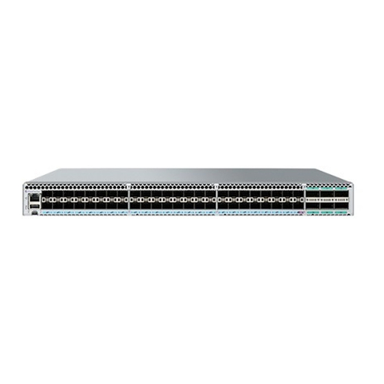
• Nonport-side view of the SLX 9540 Switch ............................15 • Device management options..................................16 Hardware features TABLE 6 ExtremeSwitching SLX 9540 Features SLX 9540 Switch Features Description Maximum 100 GbE/40 GbE ports Maximum 10 GbE/1 GbE ports Switch fabric capacity 1.08 Tbps... - Page 14 The following illustration shows the front view of the SLX 9540 Switch . FIGURE 2 SLX 9540 Switch rear view with power supply and fan assemblies For more device details, refer to ExtremeSwitching SLX 9540 Technical Specifications on page 91. ExtremeSwitching SLX 9540 Hardware Installation Guide 9036360-00 Rev AB...
-
Page 15: Port-Side View Of The Slx 9540 Switch
Power LED Lower LEDs 0-3 for QSFP ports 50, 52, 54 Nonport-side view of the SLX 9540 Switch The following illustration shows the rear-view or nonport-side of the SLX 9540 Switch. ExtremeSwitching SLX 9540 Hardware Installation Guide 9036360-00 Rev AB... -
Page 16: Device Management Options
Ethernet or serial connection ExtremeSwitching SLX-OS Management Configuration Guide REST or NETCONF/YANG APIs. Ethernet connection ExtremeSwitching SLX-OS Management Configuration Guide Standard SNMP applications Ethernet or serial connection ExtremeSwitching SLX-OS Management Configuration Guide ExtremeSwitching SLX 9540 Hardware Installation Guide 9036360-00 Rev AB... -
Page 17: Preparing For The Installation
"E", or an orange arrow with an "I." CAUTION To protect the serial port from damage, keep the cover on the port when not in use. ExtremeSwitching SLX 9540 Hardware Installation Guide 9036360-00 Rev AB... -
Page 18: Esd Precautions
This device might have more than one power cord. To reduce the risk of electric shock, disconnect all power cords before servicing. DANGER To avoid high voltage shock, do not open the device while the power is on. ExtremeSwitching SLX 9540 Hardware Installation Guide 9036360-00 Rev AB... -
Page 19: Lifting Precautions
Laser Radiation. Do Not View Directly with Optical Instruments. Class 1M Laser Products. DANGER Use only optical transceivers that are qualified by Extreme Networks, Inc. and comply with the FDA Class 1 radiation performance requirements defined in 21 CFR Subchapter I, and with IEC 60825 and EN60825. Optical products that do not comply with these standards might emit light that is hazardous to the eyes. -
Page 20: Environmental Considerations
Before plugging a cable to any port, be sure to discharge any static charge stored on the cable by touching the electrical contacts to ground surface. • You should not use tie wraps with fiber-optic cables because they are easily overtightened and can damage the optical fibers. Velcro-like wraps are recommended. ExtremeSwitching SLX 9540 Hardware Installation Guide 9036360-00 Rev AB... -
Page 21: Quick Installation Checklist
Extreme SLX-OS Management Configuration Guide pinging them and tracing routes. Continue configuring the device using the Extreme SLX-OS Management Configuration Guide CLI. Secure access to the device. Extreme SLX-OS Management Configuration Guide ExtremeSwitching SLX 9540 Hardware Installation Guide 9036360-00 Rev AB... -
Page 22: Shipping Carton Contents
Two 6-ft. power cord – Power cord retainer clip – Rubber feet, required for setting up the device as a standalone unit China-RoHS Hazardous/Toxic Substance statement – EULA/Read-Me document – USB drive, 8G ExtremeSwitching SLX 9540 Hardware Installation Guide 9036360-00 Rev AB... -
Page 23: Mounting The Device
Make sure the rack housing the device is adequately secured to prevent it from becoming unstable or falling over. CAUTION Make sure the airflow around the front, and back of the device is not restricted. CAUTION Never leave tools inside the chassis. ExtremeSwitching SLX 9540 Hardware Installation Guide 9036360-00 Rev AB... -
Page 24: Standalone Installation
To mount the product into a four-post rack, you can also order the four-post rack kit with the part number XEN-R000296. For the procedure to install this kit, refer to “Installing the Universal Four-Post Rack Kit (XEN-R000296)” on page 25. ExtremeSwitching SLX 9540 Hardware Installation Guide 9036360-00 Rev AB... -
Page 25: Four-Post Rack Mount Kit Installation (Xbr-R000297)
#2 Phillips torque screwdriver • 1/4-inch slotted-blade torque screwdriver Parts list The following parts are provided with the four-post flush-mount rack kit (XBR-R000297). Verify that the items below are included in the parts list. ExtremeSwitching SLX 9540 Hardware Installation Guide 9036360-00 Rev AB... -
Page 26: Flush-Front Mounting
The device must be turned off and disconnected from the fabric during this procedure. Complete the following tasks to install the device in a four-post rack. Attaching the front brackets on page 27. Installing the device in the rack on page 27. ExtremeSwitching SLX 9540 Hardware Installation Guide 9036360-00 Rev AB... - Page 27 Attach the right front bracket to the right front rack post using three 10-32 x 5/8-in. panhead screws and three retainer nuts. Use the three holes in the bracket. ExtremeSwitching SLX 9540 Hardware Installation Guide 9036360-00 Rev AB...
- Page 28 Attach the left rear bracket to the left rear rack post using three 10-32 x 5/8-in. panhead screws and three retainer nuts. Use the three holes in the bracket. Tighten all the 10-32 x 5/8-in. screws to a torque of 25 in-lb (29 cm-kg). ExtremeSwitching SLX 9540 Hardware Installation Guide 9036360-00 Rev AB...
-
Page 29: Installing The Universal Two-Post Rack Kit (Xen-R000294)
Installing the Universal Two-Post Rack Kit (XEN- R000294) Use the following instructions to install an Extreme Networks 1U or 2U device in a two-post telecommunications (Telco) rack using the Universal Two-Post Rack Kit (XEN-R000294). There are two ways you can mount the device in a two-post rack: •... -
Page 30: Installation Requirements
The following items are required to install the device using the Universal Two-Post Rack Kit: • #2 Phillips torque screwdriver • 1/4-inch slotted-blade torque screwdriver Parts list The following parts are provided with the Universal Two-Post Rack Kit (XEN-R000294). ExtremeSwitching SLX 9540 Hardware Installation Guide 9036360-00 Rev AB... -
Page 31: Flush-Front Mounting
The device must be turned off and disconnected from the fabric during this procedure. • The illustrations in this document show a 1U device, but the instructions are the same for a 2U device. ExtremeSwitching SLX 9540 Hardware Installation Guide 9036360-00 Rev AB... - Page 32 Tighten all the 8-32 x 5/16-in. screws to a torque of 15 in-lb (17 cm-kg). FIGURE 11 Attaching the front brackets The device Screws, 8-32 x 5/16-in., flathead Phillips Front brackets, right and left ExtremeSwitching SLX 9540 Hardware Installation Guide 9036360-00 Rev AB...
- Page 33 Attach the bracket to the right rack upright using two 10-32 x 5/8-in. panhead screws and two retainer nuts. Use the upper and lower holes in the bracket. Repeat step 2 and step 3 to attach the left rear bracket to the left rack upright. ExtremeSwitching SLX 9540 Hardware Installation Guide 9036360-00 Rev AB...
- Page 34 Align the left rear bracket to the left rear of the device and use four 8-32 x 5/16-in. panhead screws to attach the bracket to the device. Again, use the upper and lower slots in the bracket. ExtremeSwitching SLX 9540 Hardware Installation Guide 9036360-00 Rev AB...
-
Page 35: Mid-Mounting
Complete the following steps to attach the front brackets to the device. Position the right front bracket with the flat side against the right side of the device, as shown in Figure ExtremeSwitching SLX 9540 Hardware Installation Guide 9036360-00 Rev AB... - Page 36 Attach the left front bracket to the left rack upright using two 10-32 x 5/8-in. screws and two retainer nuts. Use the upper and lower holes in the bracket. ExtremeSwitching SLX 9540 Hardware Installation Guide 9036360-00 Rev AB...
- Page 37 Attach the brackets to the right rack upright using two 10-32 x 5/8-in. panhead screws and two retainer nuts. Repeat step 2 and step 3 to attach the left rear bracket to the left rack upright. ExtremeSwitching SLX 9540 Hardware Installation Guide 9036360-00 Rev AB...
- Page 38 Align the left rear bracket to the left rear of the device and use four 8-32 x 5/16-in. panhead screws to attach the bracket to the device. Again, use the upper and lower slots in the bracket. ExtremeSwitching SLX 9540 Hardware Installation Guide 9036360-00 Rev AB...
-
Page 39: Installing The Universal Four-Post Rack Kit (Xen-R000296)
L-12.7 cm (L-5 in.) 81.28 cm (32 in.) mounts. Applicable to port-side flush mounts. L-12.7 cm (L-5 in.) 81.28 cm (32 in.) Applicable to nonport-side flush mounts. 81.28 cm (32 in.) ExtremeSwitching SLX 9540 Hardware Installation Guide 9036360-00 Rev AB... -
Page 40: Installation Requirements
The following items are required to install the device using the Universal Four-Post Rack Kit: • #2 Phillips torque screwdriver • 1/4-inch slotted-blade torque screwdriver Parts list The following parts are provided with the Universal Four-Post Rack Kit (XEN-R000296). ExtremeSwitching SLX 9540 Hardware Installation Guide 9036360-00 Rev AB... - Page 41 Screw, 8-32 x 5/16-in., panhead Phillips (8) Screw, 8-32 x 5/16-in., flathead Phillips (16) Screw, 8-32 x 5/16-in., flathead Phillips (16) Screw, 10-32 x 5/8-in., panhead Phillips (8) 10. Retainer nut, 10-32 (8) ExtremeSwitching SLX 9540 Hardware Installation Guide 9036360-00 Rev AB...
-
Page 42: Flush-Front Mounting
Use the upper and lower screw holes, leaving the center holes empty. Repeat step 1 and step 2 to attach the left front bracket to the left side of the device. ExtremeSwitching SLX 9540 Hardware Installation Guide 9036360-00 Rev AB... - Page 43 Use the upper and lower screw holes, leaving the center holes empty. Repeat step 2 and step 3 to attach the left bracket extension to the left side of the device. ExtremeSwitching SLX 9540 Hardware Installation Guide 9036360-00 Rev AB...
- Page 44 Attach the left front bracket to the left front rack post using two 10-32 x 5/8-in. panhead screws and two retainer nuts. Use the upper and lower holes in the bracket. ExtremeSwitching SLX 9540 Hardware Installation Guide 9036360-00 Rev AB...
- Page 45 If possible, leave at least one empty vertical pair of holes between the screws for better support. Repeat step 2 and 3 to attach the left rear bracket to the left bracket extension. ExtremeSwitching SLX 9540 Hardware Installation Guide 9036360-00 Rev AB...
- Page 46 Attach the left rear bracket to the left rear rack post using two 10-32 x 5/8-in. panhead screws and two retainer nuts. Use the upper and lower holes in the bracket. ExtremeSwitching SLX 9540 Hardware Installation Guide 9036360-00 Rev AB...
-
Page 47: Flush-Rear (Recessed) Mounting
49 Attaching the rear brackets to the extensions at the front of the device on page 50 Attaching the rear brackets to the front rack posts on page 52 ExtremeSwitching SLX 9540 Hardware Installation Guide 9036360-00 Rev AB... - Page 48 Insert four 8-32 x 5/16-in. flathead screws through the vertically aligned holes in the bracket extension and then into the holes on the side of the device. Use the upper and lower screw holes, leaving the center holes empty. ExtremeSwitching SLX 9540 Hardware Installation Guide 9036360-00 Rev AB...
- Page 49 Attach the left front bracket to the left rear rack post using two 10-32 x 5/8-in. panhead screws and two retainer nuts. Use the upper and lower holes in the bracket. ExtremeSwitching SLX 9540 Hardware Installation Guide 9036360-00 Rev AB...
- Page 50 Attach the brackets using four 6-32 x 1/4-in. panhead screws. Repeat step 2 and step 3 to attach the left rear bracket to the left extension. ExtremeSwitching SLX 9540 Hardware Installation Guide 9036360-00 Rev AB...
- Page 51 FIGURE 28 Attaching the rear brackets to the extensions at the front of the device Rear brackets, short Screws, 6-32 x 1/4-in., panhead Phillips FIGURE 29 Attaching the short or long rear brackets to the extensions ExtremeSwitching SLX 9540 Hardware Installation Guide 9036360-00 Rev AB...
- Page 52 Tighten all the 10-32 x 5/8-in. screws to a torque of 25 in-lb (29 cm-kg). FIGURE 30 Attaching the rear brackets to the front rack posts Screws, 10-32 x 5/8-in., panhead Phillips Retainer nuts, 10-32 ExtremeSwitching SLX 9540 Hardware Installation Guide 9036360-00 Rev AB...
-
Page 53: Initial Setup And Verification
SLX 9540 Switch. Verify that the device operates correctly. • Check the LEDs to verify operation of module components in the device. Refer to ExtremeSwitching SLX 9540 Technical Specifications on page 91. ExtremeSwitching SLX 9540 Hardware Installation Guide 9036360-00 Rev AB... -
Page 54: Items Required
Connect the power cables to the 100-240 VAC or 48-60 VDC power source. The power sources should be on separate circuits to protect against power failure. Ensure that the power cords have a minimum service loop of 6 inches available and are routed to avoid stress. ExtremeSwitching SLX 9540 Hardware Installation Guide 9036360-00 Rev AB... -
Page 55: Establishing A Serial Connection
Access the device using a terminal emulator application (such as HyperTerminal in a Windows environment or Tip in a UNIX environment). Disable any serial communication programs running on the workstation (such as synchronization programs). ExtremeSwitching SLX 9540 Hardware Installation Guide 9036360-00 Rev AB... - Page 56 (.), and the underscore (_) only. Passwords are case-sensitive, and they are not displayed when you enter them on the command line. For more information on passwords, refer to Extreme SLX-OS Security Configuration Guide for the SLX 9540 device. ExtremeSwitching SLX 9540 Hardware Installation Guide 9036360-00 Rev AB...
-
Page 57: Configuring A Static Ip Address
Connecting interface modules to a private network or VLAN is recommended. After establishing an Ethernet connection, you can complete the device configuration using a serial console connection, Telnet connection, or existing management applications. ExtremeSwitching SLX 9540 Hardware Installation Guide 9036360-00 Rev AB... -
Page 58: Customizing The Chassis And Host Names
Enter configure terminal to enter global configuration mode. Enter switch-attributes chassis-name chassis-name, where chassis-name is the new chassis name. Enter exit to return to privileged EXEC mode. To verify the new chassis name, enter the show chassis command. ExtremeSwitching SLX 9540 Hardware Installation Guide 9036360-00 Rev AB... -
Page 59: Configuring The Dns Service
A Telnet session using the chassis management IP address. Log in to the device using admin as your login name. If you have not changed the default password, use password for password. ExtremeSwitching SLX 9540 Hardware Installation Guide 9036360-00 Rev AB... -
Page 60: Backing Up The Configuration
USB drive attached to the device (for example, plugged into the USB port in the management module). Installing cable management kit For more information about installing cable management, refer to managing cables section Managing cables on page 63. ExtremeSwitching SLX 9540 Hardware Installation Guide 9036360-00 Rev AB... -
Page 61: Transceivers And Cables
Optical transceiver extraction tool (for 10 Gbps transceiver only) NOTE Most Extreme devices come with a transceiver extraction tool and holster. The extraction tool is designed to remove transceivers from modules where the space is limited. ExtremeSwitching SLX 9540 Hardware Installation Guide 9036360-00 Rev AB... -
Page 62: Precautions Specific To Transceivers And Cables
All fiber-optic interfaces use Class 1 lasers. DANGER Use only optical transceivers that are qualified by Extreme Networks, Inc. and comply with the FDA Class 1 radiation performance requirements defined in 21 CFR Subchapter I, and with IEC 60825 and EN60825. Optical products that do not comply with these standards might emit light that is hazardous to the eyes. -
Page 63: Managing Cables
To insert an SFP+ transceiver, complete the following steps. NOTE Route cables to the side so that the line cards can be removed without disturbing the cables to the other line cards. ExtremeSwitching SLX 9540 Hardware Installation Guide 9036360-00 Rev AB... - Page 64 If the transceiver uses a bail latch mechanism (10 GbE transceivers only), ensure that the bail (wire handle) is in the unlocked position, grasp the transceiver, and push it into the port until firmly seated. Close the bail to latch the transceiver in the slot. ExtremeSwitching SLX 9540 Hardware Installation Guide 9036360-00 Rev AB...
-
Page 65: Replacing An Sfp+ Transceiver
You may damage the cable as well as the transceiver. Replacing an SFP+ transceiver Complete the following steps to remove and then install a new SFP+ transceiver. Remove any cables that are inserted into the transceiver. ExtremeSwitching SLX 9540 Hardware Installation Guide 9036360-00 Rev AB... - Page 66 If transceiver has a pull tab, grasp the pull tab and pull the transceiver straight out from the port. NOTE Grasp the pull tab near the body of the transceiver to reduce the chances of bending the pull tab. As the transceiver may be hot, avoid touching it. ExtremeSwitching SLX 9540 Hardware Installation Guide 9036360-00 Rev AB...
-
Page 67: Installing A Qsfp28 Transceiver
QSFP28 must be replaced. • Some QSFP28 transceivers have an integrated cable attached. You do not need to install a separate cable. ExtremeSwitching SLX 9540 Hardware Installation Guide 9036360-00 Rev AB... - Page 68 QSFP28 transceiver. You may damage the cable as well as the transceiver. Organize cables to avoid covering LEDs and air vents so that LCs can be removed. Refer to Managing cables on page 63 for more information. ExtremeSwitching SLX 9540 Hardware Installation Guide 9036360-00 Rev AB...
-
Page 69: Replacing A Qsfp28 Transceiver
The following figure uses a generic interface module. Your interface module might look different. FIGURE 39 Replacing a QSFP28 optical transceiver into blade port Pull tab QSFP28 transceiver QSFP28 cable connector ExtremeSwitching SLX 9540 Hardware Installation Guide 9036360-00 Rev AB... -
Page 70: Breakout Cables
40G-QSFP-SR4-INT (with fiber breakout cables and additional 10GbE optics). • 40G-QSFP-ESR4 (with fiber breakout cables and additional 10GbE optics). FIGURE 40 QSFP+ to 4 SFP+ (4 x 10 GbE) direct-attach copper breakout cable ExtremeSwitching SLX 9540 Hardware Installation Guide 9036360-00 Rev AB... -
Page 71: Verifying Transceiver Operation
LED becomes solid green. When traffic is detected on the port, the light becomes blinking green. You can also enter the show interface status and show ip interface brief commands to verify proper transceiver operation. ExtremeSwitching SLX 9540 Hardware Installation Guide 9036360-00 Rev AB... - Page 72 ExtremeSwitching SLX 9540 Hardware Installation Guide 9036360-00 Rev AB...
-
Page 73: Monitoring The Device
Four single-color status LEDs (green) for each of the 48 QSFP28 ports that indicate the status of the ports in 100 GbE mode, 2x50 GbE mode, 40 GbE mode, and 4x10 GbE mode The figure below shows the LEDs on the SLX 9540 Switch front panel. ExtremeSwitching SLX 9540 Hardware Installation Guide 9036360-00 Rev AB... -
Page 74: Led Indications
Valid power. All monitored voltages are nominal Status (bicolor) Blinking Amber-Green Attention TBD by SW Amber Fault/ initial state This LED shall be lit during the reboot Green Board is operational 1G Ethernet Status ExtremeSwitching SLX 9540 Hardware Installation Guide 9036360-00 Rev AB... - Page 75 Home Run Port LEDs (Amber only. Note: This LED is shared with SFP Port 48 LED) Solid Off No Link Solid Amber ON Link, no traffic Amber Flicker Link, Activity ExtremeSwitching SLX 9540 Hardware Installation Guide 9036360-00 Rev AB...
- Page 76 ExtremeSwitching SLX 9540 Hardware Installation Guide 9036360-00 Rev AB...
-
Page 77: Power Supplies
If the second power supply and any fan slots are unused, you must cover them with filler panels. NOTE Extreme Networks recommends that the SLX 9540 device operate with two power supplies and five fan assemblies installed. If a power supply or fan assembly fails, it must be replaced as soon as possible. - Page 78 Power supply overview FIGURE 42 AC power supply Release lever Power supply handle ExtremeSwitching SLX 9540 Hardware Installation Guide 9036360-00 Rev AB...
-
Page 79: Precautions Specific To Power Supplies
CAUTION Disassembling any part of the power supply and fan assembly voids the warranty and regulatory certifications. There are no user-serviceable parts inside the power supply and fan assembly. ExtremeSwitching SLX 9540 Hardware Installation Guide 9036360-00 Rev AB... -
Page 80: Identifying The Airflow Direction
When installing or replacing a power supply unit, keep in mind the following: • Power supplies can be swapped in or out while the device is running. The remaining power supply provides enough power for the device. ExtremeSwitching SLX 9540 Hardware Installation Guide 9036360-00 Rev AB... -
Page 81: Inserting A New Ac Power Supply
Holding the power supply level, guide it into the carrier rails on each side and gently push it all the way into the slot, ensuring that it firmly engages with the connector and the release lever clicks into its locked position. ExtremeSwitching SLX 9540 Hardware Installation Guide 9036360-00 Rev AB... -
Page 82: Inserting A New Dc Power Supply
Due to the limited space for the safety ground wire, we recommend using a 90 angled lug such as: • TE Connectivity Solistrand "16-14HD 90 Ring 8", part number 184269-1 for 14 AWG wire • PIDG 12-10 Ring #8, 90-DEG, part number 1958340-1 for 12 or 10 AWG wire ExtremeSwitching SLX 9540 Hardware Installation Guide 9036360-00 Rev AB... -
Page 83: Grounding The Slx 9540 Device
Before connecting power to the device, the grounding terminal must be connected to ground to ensure proper operation and to meet electromagnetic interference (EMI) and safety requirements. ExtremeSwitching SLX 9540 Hardware Installation Guide 9036360-00 Rev AB... - Page 84 Attach the 12 AWG stranded copper wire to the grounding terminal on the SLX 9540 device using the screws included in the grounding kit. Attach the grounding wire to a grounding point. NOTE The terminal for the connection of a grounding conductor is not to be used with an aluminum conductor. ExtremeSwitching SLX 9540 Hardware Installation Guide 9036360-00 Rev AB...
-
Page 85: Fan Assemblies
Fan assemby overview The ExtremeSwitching SLX 9540 device includes six hot-swappable fan unit slots. It is shipped with 5 fan FRUs for a (4+1 redundancy). The switch is capable of running on one power supply and four fan assembly. The fifth fan assembly and the second power supply provide additional redundancy. -
Page 86: Precautions Specific To Fan Assemblies
If you do not install a module or a power supply in a slot, you must keep the slot filler panel in place. If you run the chassis with an uncovered slot, the system will overheat. ExtremeSwitching SLX 9540 Hardware Installation Guide 9036360-00 Rev AB... -
Page 87: Identifying The Airflow Direction
"E", or an orange arrow with an "I." Inserting a new fan assembly Use the following steps to install a fan assembly in the SLX 9540 switch. ExtremeSwitching SLX 9540 Hardware Installation Guide 9036360-00 Rev AB... - Page 88 When you are sure the fan assembly has properly engaged the connector, tighten the captive screw to secure the fan assembly in the slot. NOTE The fans are controlled automatically by the device. ExtremeSwitching SLX 9540 Hardware Installation Guide 9036360-00 Rev AB...
- Page 89 If you do not install a module or a power supply in a slot, you must keep the slot filler panel in place. If you run the chassis with an uncovered slot, the system will overheat. ExtremeSwitching SLX 9540 Hardware Installation Guide 9036360-00 Rev AB...
- Page 90 ExtremeSwitching SLX 9540 Hardware Installation Guide 9036360-00 Rev AB...
-
Page 91: Extremeswitching Slx 9540 Technical Specifications
Input AC voltage is out of range. • LED 1: Green and LED 2: Yellow - Output voltage is out of range • LED 1: Green and LED 2: Flashing Yellow/Green - Over-temperature warning or fan error ExtremeSwitching SLX 9540 Hardware Installation Guide 9036360-00 Rev AB... -
Page 92: Other
AC power supply 581 W Operating noise 52.6 dBA (5 fan assemblies, 25°C, typical loading) MTBF (25°C, 60% CL, 306,419 hours with DC power supply Telec) 327,539 hours with AC power supply ExtremeSwitching SLX 9540 Hardware Installation Guide 9036360-00 Rev AB... -
Page 93: Power Supply Specifications (Per Psu)
QSFP28 ports 100 GbE QSFP28 ports SFP+ ports The SFP+ ports can support 10GbE/1GbE interfaces. There are 48 x SFP+ ports. Ethernet management port RJ-45 port with 10/100/1000 Mbps auto-negotiating capability ExtremeSwitching SLX 9540 Hardware Installation Guide 9036360-00 Rev AB... -
Page 94: Serial Port Specifications (Pinout Rj-45)
None Stop bits Flow control None Memory specifications Parameter Type Size Main memory DDR4 16 GB Boot flash NOR Flash 32 MB M.2 SATA III (2 slots) 64 GB per slot ExtremeSwitching SLX 9540 Hardware Installation Guide 9036360-00 Rev AB... -
Page 95: Regulatory Compliance (Emc)
30/2011/TT-BCT - Vietnam circular. • SJ/T 11363-2006 Requirements for Concentration Limits for Certain Hazardous Substances in EIPs (China). • SJ/T 11364-2006 Marking for the Control of Pollution Caused by EIPs (China). ExtremeSwitching SLX 9540 Hardware Installation Guide 9036360-00 Rev AB... - Page 96 ExtremeSwitching SLX 9540 Hardware Installation Guide 9036360-00 Rev AB...
-
Page 97: Regulatory Statements
EN61000-3-2/JEIDA (European and Japanese Harmonics Spec) – EN61000-3-3 China ROHS Refer to the latest revision of the China ROHS document (P/N 53‐1000428‐xx) which ships with the product. BSMI statement (Taiwan) Warning: ExtremeSwitching SLX 9540 Hardware Installation Guide 9036360-00 Rev AB... -
Page 98: Canadian Requirements
This Class A digital apparatus meets all requirements of the Canadian Interference-Causing Equipment Regulations, ICES-003 Class A. Cet appareil numérique de la classe A est conforme à la norme NMB-003 du Canada. China CCC statement ExtremeSwitching SLX 9540 Hardware Installation Guide 9036360-00 Rev AB... -
Page 99: Europe And Australia (Cispr 32 Class A Warning)
Class A device (Broadcasting Communication Device for Office Use): This device obtained EMC registration for office use (Class A), and may be used in places other than home. Sellers and/or users need to take note of this. ExtremeSwitching SLX 9540 Hardware Installation Guide 9036360-00 Rev AB... -
Page 100: Vcci Statement
(VCCI). If this equipment is used in a domestic environment, radio disturbance might arise. When such trouble occurs, the user might be required to take corrective actions. Japan power cord English translation of above statement ATTENTION: Never use the power cord packed with your equipment for other products. ExtremeSwitching SLX 9540 Hardware Installation Guide 9036360-00 Rev AB... -
Page 101: Cautions And Danger Notices
Stellen Sie sicher, dass an der Vorderseite, den Seiten und an der Rückseite der Luftstrom nicht behindert wird. MISE EN GARDE Vérifiez que rien ne restreint la circulation d'air devant, derrière et sur les côtés du dispositif et qu'elle peut se faire librement. ExtremeSwitching SLX 9540 Hardware Installation Guide 9036360-00 Rev AB... - Page 102 Utilisez les vis mentionnées dans les instructions. L'utilisation de vis plus longues peut endommager l'appareil. PRECAUCIÓN Utilice los tornillos especificados en el procedimiento. Si utiliza tornillos de mayor longitud, podría dañar el dispositivo. ExtremeSwitching SLX 9540 Hardware Installation Guide 9036360-00 Rev AB...
- Page 103 Es empfiehlt sich die Installation eines separaten Stromkreiszweiges für jede Elektroschnur als Redundanz im Fall des Ausfalls eines Stromkreises. MISE EN GARDE Utilisez un circuit de dérivation différent pour chaque cordon d’alimentation ainsi, il y aura un circuit redondant en cas de panne d’un des circuits. ExtremeSwitching SLX 9540 Hardware Installation Guide 9036360-00 Rev AB...
-
Page 104: Danger Notices
A Danger statement indicates conditions or situations that can be potentially lethal or extremely hazardous to you. Safety labels are also attached directly to products to warn of these conditions or situations. ExtremeSwitching SLX 9540 Hardware Installation Guide 9036360-00 Rev AB... -
Page 105: General Dangers
Vérifiez que le bâti abritant le dispositif est bien fixé afin qu'il ne devienne pas instable ou qu'il ne risque pas de tomber. PELIGRO Verifique que el bastidor que alberga el instrumento está asegurado correctamente para evitar que pueda hacerse inestable o que caiga. ExtremeSwitching SLX 9540 Hardware Installation Guide 9036360-00 Rev AB... - Page 106 Cette marque vous assure que vous pouvez utiliser le cordon d'alimentation avec le dispositif en toute sécurité. ExtremeSwitching SLX 9540 Hardware Installation Guide 9036360-00 Rev AB...
- Page 107 Alle Glasfaser-Schnittstellen verwenden Laser der Klasse 1. DANGER Toutes les interfaces en fibre optique utilisent des lasers de classe 1. PELIGRO Todas las interfaces de fibra óptica utilizan láser de clase 1. ExtremeSwitching SLX 9540 Hardware Installation Guide 9036360-00 Rev AB...
- Page 108 警告 DANGER Use only optical transceivers that are qualified by Extreme Networks, Inc. and comply with the FDA Class 1 radiation performance requirements defined in 21 CFR Subchapter I, and with IEC 60825 and EN60825. Optical products that do not comply with these standards might emit light that is hazardous to the eyes.
Need help?
Do you have a question about the ExtremeSwitching SLX 9540 and is the answer not in the manual?
Questions and answers