Extreme Networks Alpine 3804 Hardware Manual
Extreme alpine 3804: hardware guide
Hide thumbs
Also See for Alpine 3804:
- Installation notes (8 pages) ,
- Installation note (4 pages) ,
- Installation manual (4 pages)

Subscribe to Our Youtube Channel
Related Manuals for Extreme Networks Alpine 3804


Summary of Contents for Extreme Networks Alpine 3804
- Page 1 Extreme Networks Consolidated Hardware Guide Extreme Networks, Inc. 3585 Monroe Street Santa Clara, California 95051 (888) 257-3000 http://www.extremenetworks.com Published: December 2002 Part number: 100093-00 Rev. 03...
- Page 2 Extreme Networks, Inc., which may be registered or pending registration in certain jurisdictions. The Extreme Turbodrive logo is a service mark of Extreme Networks, which may be registered or pending registration in certain jurisdictions. All other registered trademarks, trademarks and service marks are property of their respective owners.
-
Page 3: Table Of Contents
Installing and Removing a Mini-GBIC GBIC Type and Hardware/Software Support GBIC Media Types and Distances GBIC Specifications Long Range GBIC System Budgets Safety Information Preparing to Install or Replace a GBIC Installing or Replacing a GBIC Extreme Networks Consolidated Hardware Guide... - Page 4 Summit Switch Overview Summit Switch Models Summary of Features Summit “i” series and non-”i” series switches Summit24e2 Summit24e3 SummitPx1 Memory Requirements Port Connections Following Safety Information Chapter 4 Summit Switch Models Switch Models 4 - Contents Extreme Networks Consolidated Hardware Guide...
- Page 5 Summit48i Switch Front View GBIC Ports LEDs Summit48i Switch Rear View Power Sockets Label Reset Button Console Port Summit48si Switch Front View Mini-GBIC Ports Console Port LEDs Summit48si Switch Rear View Power Supplies Reset Button Extreme Networks Consolidated Hardware Guide Contents - 5...
- Page 6 Summit24e3 Switch Front View Mini-GBIC Ports LEDs Console Port Reset Button Summit24e3 Switch Rear View Power Socket Label Summit24e3 Switch LEDs SummitPx1 Application Switch Front View GBIC Network Interface LEDs Ethernet Management Port 6 - Contents Extreme Networks Consolidated Hardware Guide...
- Page 7 Alpine 3800 Series Switch Chassis Alpine 3800 Series Architecture Alpine 3808 Switch Front View Alpine 3808 Switch Rear View Alpine 3804 Switch Front View Alpine 3804 Switch Rear View Alpine 3802 Switch Front View Alpine 3802 Switch Rear View Alpine 3802 Software Enhancements...
- Page 8 Chapter 8 Alpine 3800 Series Switch Power Supplies Power Supply LEDs Installing the Alpine 3808 and the Alpine 3804 AC Power Supply Verifying a Successful Installation Removing the Alpine 3808 and the Alpine 3804 AC Power Supply Supplying Power to the Alpine 3802 AC Power Supply...
- Page 9 Alpine 3800 Series Switch Fan Tray Alpine 3808 Fan Tray Alpine 3804 Fan Tray Alpine 3802 Fan Tray Removing the Alpine 3808 or Alpine 3804 Fan Tray Installing the Alpine 3808 or Alpine 3804 Fan Tray Part 5 BlackDiamond Switch Chapter 12...
- Page 10 F96Ti Module F32Fi Module P3cSi, P3cMi, P12cSi, and P12cMi Modules MPLS Module A3cSi and A3cMi Modules I/O Module LEDs Installing I/O Modules Verifying the I/O Module Installation LED Indicators Displaying Slot Status Information 10 - Contents Extreme Networks Consolidated Hardware Guide...
- Page 11 Appendix A Safety Information Important Safety Information Power Power Cable Fuse Connections Lithium Battery Appendix B Switch Technical Specifications Appendix C Module Technical Specifications Alpine Modules BlackDiamond Modules Common Module Specifications Index Extreme Networks Consolidated Hardware Guide Contents - 11...
- Page 12 12 - Contents Extreme Networks Consolidated Hardware Guide...
- Page 13 Total optical system budgets for long range GBICs GBIC modules Airflow through the Alpine 3808 chassis Airflow through the Alpine 3804 chassis Airflow through the Alpine 3802 chassis Airflow through the BlackDiamond 6816 chassis Airflow through the BlackDiamond 6808 chassis...
- Page 14 The Alpine 3808 chassis requires 8 screws to be securely mounted in a rack The Alpine 3804 chassis requires 8 screws to be securely mounted in a rack The Alpine 3802 chassis requires 4 screws to be securely mounted in a rack...
- Page 15 WM-1T3i module Alpine 3808 fan tray Alpine 3804 fan tray Front view of the BlackDiamond 6816 switch with sample I/O modules Rear view of the BlackDiamond 6816 switch Front view of the BlackDiamond 6808 switch with sample I/O modules Rear view of the BlackDiamond 6808 switch...
- Page 16 BlackDiamond 6808 fan tray BlackDiamond 6804 fan tray An example of removing the BlackDiamond 6816 or the BlackDiamond 6804 fan tray An example of removing the BlackDiamond 6808 fan tray Null-modem cable pinouts PC-AT serial null-modem cable pinouts Extreme Networks Consolidated Hardware Guide...
- Page 17 Switch LED activity for the Summit1i, Summit5i, Summit7i, Summit48i, and Summit48si GBIC types and maximum distances GBIC types and maximum distances Switch LED activity for the Summit4, Summit4/FX, Summit24, and Summit48 97 GBIC types and maximum distances Summit24e2 switch LED activity Summit24e3 switch LED activity...
- Page 18 Supported power supplies for the Alpine 3800 series switch Alpine 3808 and Alpine 3804 power supply LED Alpine 3802 power supply LEDs Source DC power specifications for the Alpine 3808 and the Alpine 3804 Source DC power specifications for the Alpine 3802 SMMi LEDs...
- Page 19 Extreme Networks Consolidated Hardware Guide Summit non-“i” series switch specifications Summit24e2 switch specifications Summit24e3 switch specifications SummitPx1 application switch specifications Alpine 3800 series switch specifications BlackDiamond 6800 series switch specifications Common switch specifications SMMi module specifications GM-4Ti, GM-4Xi, and GM-4Si module specifications...
- Page 20 20 - Tables Extreme Networks Consolidated Hardware Guide...
-
Page 21: Preface
This preface provides an overview of this guide, describes guide conventions, and lists other publications that might be useful. NOTE To ensure proper operation of your Extreme Networks equipment, read this guide before you install any Extreme Networks equipment. Introduction This guide provides the required information to install an Extreme Networks Summit ™... -
Page 22: Conventions
Related Publications The Extreme Networks switch documentation set includes: • Extreme Networks Consolidated Hardware Guide (this guide) • ExtremeWare Software User Guide • ExtremeWare Quick Reference Guide • ExtremeWare Software Command Reference Guide •... -
Page 23: About This Guide
You can also purchase Extreme Networks documentation from the Extreme Networks website. About This Guide This guide describes how to prepare your site and how to install, maintain, and operate your Extreme Networks switch. It contains information on features that are common to all switches, as well as switch-specific features. -
Page 24: How To Use This Guide
The Summit-, Alpine-, and BlackDiamond-specific chapters contain information that is applicable to that family of switch only. All other chapters are applicable to any Extreme Networks switch. For switch-specific information, be sure to read the applicable switch-specific chapter. For example, if you have a BlackDiamond switch and you need to remove and replace an I/O module, see “Removing I/O Modules”... -
Page 25: Part 1 Common Features
Part 1 Common Features... -
Page 27: Summary Of Common Switch Features
Summary of Common Switch Features This chapter describes the features that are shared in common by the Extreme Networks family of switches. The following topics are described in greater detail: • Software Images on page 27 • Full-Duplex Support on page 28 •... -
Page 28: Full-Duplex Support
• BlackDiamond—Management Switch Fabric Module (MSM64i) for the BlackDiamond series switch Extreme Networks does not recommend that you use the management port to route traffic to any front panel port on the switch. The management port is designed for switch management purposes. - Page 29 General Total system budget Total optical system budget for the SX mini-GBIC is 11.5 dBm. Extreme Networks recommends that 3 dBm of the total budget be reserved for losses induced by cable splices/connectors and operating margin. While 8.5 dBm remains available for cable induced attenuation, the 1000BASE-SX standard specifies supported distances of 275 meters over 62.5 micron multimode fiber and 550 meters over 50...
-
Page 30: Safety Information
CAUTION Mini-GBICs can emit invisible laser radiation. Avoid direct eye exposure to beam. Mini-GBICs are class 1 laser devices, and they operate at 3.3 V. Use only Extreme Networks-certified mini-GBIC devices. If you see an amber blinking mini-GBIC port status LED after you install a mini-GBIC into the Summit24e3 or Summit48si switch, this means the mini-GBIC is not certified by Extreme Networks. -
Page 31: Mini-Gbic Modules
If you see an amber blinking mini-GBIC port status LED after you install a mini-GBIC into the Summit24e3 or Summit48si switch, this means the mini-GBIC is not certified by Extreme Networks. To correct this problem, install an Extreme Networks-certified mini-GBIC, available from Extreme Networks, into the port in the switch. -
Page 32: Gbic Type And Hardware/Software Support
Summary of Common Switch Features GBIC Type and Hardware/Software Support Most Extreme Networks switches support two types of GBICs: the Parallel ID GBIC and the Serial ID GBIC. The switch can identify the media type for the GBIC that is installed. Initial ExtremeWare software versions do not support Serial ID GBICs. - Page 33 Table 10: ZX GBIC Rev 03 specifications Parameter Transceiver Optical output power Center wavelength Receiver Optical input power sensitivity Optical input power maximum Operating wavelength Extreme Networks Consolidated Hardware Guide Minimum Typical Maximum -17 dBm 0 dBm 830 nm 860 nm Minimum...
- Page 34 If you see one of the following on the label, you have a ZX GBIC Rev 03 module: • DVA-1203 sticker near the top of the label that covers the Extreme Networks logo • ZX GBIC (1203) text near the top of the label •...
-
Page 35: Long Range Gbic System Budgets
(for example, 0.25 db/km), Extreme Networks recommends that 3 dB of the total budget be reserved for losses induced by cable splices, connectors, and operating margin. Figure 2 shows the total optical system budget between long range GBICs. -
Page 36: Safety Information
GBICs can emit invisible laser radiation. Avoid direct eye exposure to beam. GBICs are class 1 laser devices, and they operate at 5 V. Use only Extreme-approved devices. Remove the SC fiber-optic or the RJ-45 connector from the GBIC prior to removing the GBIC from the I/O module or the switch. -
Page 37: Preparing To Install Or Replace A Gbic
After you complete all of these described tasks, you are ready to install or replace a GBIC. Installing or Replacing a GBIC You can add and remove GBICs from your Extreme Networks switch without powering off the system. Figure 3 shows the three types of GBIC connectors. - Page 38 GBIC out of the slot. To insert a GBIC connector: 1 Holding the GBIC by its sides, insert the GBIC into the slot on the I/O module or the switch. 2 Slide the GBIC into the slot, until you hear it click.
-
Page 39: Part 2 Site Planning
Part 2 Site Planning... -
Page 41: Site Preparation
Site Preparation This chapter describes how to prepare your site for installing Extreme Networks equipment. It contains information on environmental and cabling requirements, power requirements, and building and electrical code organizations. This chapter includes these sections: • Planning Your Site on page 42 •... -
Page 42: Planning Your Site
(or cabling). Step 3: Meeting Power Requirements To run your equipment safely, you must meet the specific power requirements for the Extreme Networks equipment that you plan to install. NOTE Review and follow the safety information before you install your equipment. - Page 43 • Ensure that your system is easily accessible for installation and service. See “Rack Specifications and Recommendations” on page 51 for specific recommendations. • Use appropriate AC power for your switch, as described in Table 15. Table 15: AC power requirements...
- Page 44 • Ensure that all system environmental requirements are met, such as ambient temperature and humidity. NOTE Extreme Networks recommends that you consult an electrical contractor for commercial building and wiring specifications. Requirements 20 A service receptacle, NEMA L6-20 (locking) for BlackDiamond 110 VAC power supplies.
- Page 45 • The Summit family of switches require 3 inches (7.62 cm) on both the left and right sides of the switch (5 inches (12.7 cm) recommended) for proper airflow. • The Alpine 3800 series chassis require 3 inches (7.62 cm) on both the left and right sides of the switch (5 inches (12.7 cm) recommended) for proper airflow.
-
Page 46: Airflow Through The Alpine 3808 Chassis
The airflow of the Alpine 3804 and Alpine 3802 moves from the left side of the chassis to the right side of the chassis as shown in Figure 5 and Figure 6. • Airflow for cooling power supplies moves left to right as you face the chassis. -
Page 47: Airflow Through The Alpine 3804 Chassis
Figure 5: Airflow through the Alpine 3804 chassis Airflow through chassis Figure 6: Airflow through the Alpine 3802 chassis Airflow through chassis Extreme Networks Consolidated Hardware Guide Meeting Site Requirements Airflow through chassis 38_air4 Airflow through chassis 3802air... -
Page 48: Airflow Through The Blackdiamond 6816 Chassis
• Airflow for cooling power supplies moves front to back as you face the chassis. • Airflow for cooling modules moves left to right as you face the chassis. Figure 7: Airflow through the BlackDiamond 6816 chassis Airflow through chassis Airflow through power supplies BD_032 Extreme Networks Consolidated Hardware Guide... -
Page 49: Airflow Through The Blackdiamond 6808 Chassis
Figure 8: Airflow through the BlackDiamond 6808 chassis Airflow through chassis POWER Airflow through power supplies Extreme Networks Consolidated Hardware Guide 50015 50015 POWER DC OUT DC OUT AC IN AC IN 50021 50021 Meeting Site Requirements BD_027... -
Page 50: Airflow Through The Blackdiamond 6804 Chassis
• Use electrostatically safe equipment and the ESD straps that are provided with your equipment. All Alpine and BlackDiamond switches come with ESD wrist strap connectors and wrist straps as shown in Figure 10. Airflow from fan tray 6804air Extreme Networks Consolidated Hardware Guide... -
Page 51: Rack Specifications And Recommendations
Figure 10: Ensure that you use an ESD wrist strap when handling switch components ESD strap connector Connected wrist strap Rack Specifications and Recommendations Racks should conform to conventional standards. In the United States, use EIA Standard RS-310C: Racks, Panels, and Associated Equipment. In countries other than the United States, use IEC Standard 297. - Page 52 Space Requirements for the Rack Provide enough space in front of and behind the switch so that you can service it easily. Allow a minimum of 48 inches (122 cm) in front of the rack and 24 inches (61 cm) behind the rack. When using a relay rack, provide a minimum of 24 inches (61 cm) of space behind the mounted equipment.
-
Page 53: Evaluating And Meeting Cable Requirements
• Radio Frequency Interference Cabling Standards We recommend using the BICSI (Building Industry Consulting Service International) RCDD (Registered Communications Distribution Designer), which is globally recognized as a standard in site planning and cabling. For information, go to http://www.bicsi.org Extreme Networks Consolidated Hardware Guide... -
Page 54: Cable Labeling And Record Keeping
• Assign a unique block of sequential numbers to the group of cables that run between each pair of wiring closets. • Assign a unique identification number to each distribution rack. • Identify all wiring closets by labeling the front panel of your Extreme Networks equipment and other hardware. • Keep accurate and current cable identification records. - Page 55 Unshielded twisted pair (UTP) cable can build up ESD charges when being pulled into a new installation. Before installing category 5 UTP cables, discharge ESD from the cable by plugging it into a port on a switch or any network device that is not powered on. Figure 12: Properly installed and bundled cable...
- Page 56 62.5/125 µm multimode fiber 62.5/125 µm multimode fiber Minimum 2 in. (5.08cm) radius in 90˚ bend 90˚ Optical fiber cable Mhz•Km Maximum Distance Rating (Meters) – 5,000 – 10,000 – 70,000 2000 2000 2000 2000 SPG_002 Extreme Networks Consolidated Hardware Guide...
-
Page 57: Rj-45 Connector Jackets
Category 5 and higher UTP cable 10BASE-T Category 3 and higher UTP cable Proprietary to Extreme Networks. Connections between two Extreme Networks 1000BASE-LX interfaces that use 10/125 µm single-mode fiber can use a maximum distance of 10,000 meters. RJ-45 Connector Jackets Use RJ-45 cable with connector jackets that are flush with the connector or that have connectors with a no-snag feature. -
Page 58: Making Network Interface Cable Connections
In areas or applications where these situations cannot be avoided, use fiber optic cabling or shielded twisted pair cabling (STP). NOTE Because harmonics can appear on the neutral line of a typical three-phase power circuit, Extreme Networks recommends using a harmonics meter in new installations. Making Network Interface Cable Connections Use the appropriate type of cable to connect the ports of your switch to another switch or router. -
Page 59: Power Supply Requirements
For more information about the power specifications of the Extreme Networks family of switches, see Appendix B, “Switch Technical Specifications” on page 297. Power Supply Requirements Adhere to the following requirements in order to operate your Extreme Networks equipment safely: •... -
Page 60: Uninterruptable Power Supply Requirements
An uninterruptible power supply (UPS) is a device that sits between a power supply (such as a wall outlet) and a device (such as a switch) to prevent outages, sags, surges, and bad harmonics from adversely affecting the performance of the device. -
Page 61: Applicable Industry Standards
UPS Transition Time Transition time is the time that is necessary for the UPS to transfer from utility power to full-load battery power. For Extreme Networks products, a transition time of less than 20 milliseconds is required for optimum performance. - Page 62 Site Preparation Extreme Networks Consolidated Hardware Guide...
-
Page 63: Part 3 Summit Switch
Part 3 Summit Switch... -
Page 65: Summit Switch Overview
This section describes the features of the Summit family of switches. If the information in the release notes differs from the information in this guide, follow the release notes. For more information about configuring the switch, refer to the ExtremeWare Software User Guide and The ExtremeWare Command Reference Guide. -
Page 66: Summit "I" Series And Non-"I" Series Switches
• Wire-speed Internet Protocol (IP) routing • IP multinetting • DHCP/BOOTP relay • Extreme Standby Router Protocol (ESRP) • Routing Information Protocol (RIP) version 1 and RIP version 2 • Open Shortest Path First (OSPF) routing protocol • Border Gateway Protocol (BGP) version 4 •... -
Page 67: Summit24E3
• Persistence • 1,000,000 simultaneous layer 7 sessions • 3,000,000 simultaneous layer 4 sessions • 2,000,000 aggregate connections • 8,000,000 client IP addresses, cookies, and SSL sessions • 64,000 real servers • 64,000 virtual servers Extreme Networks Consolidated Hardware Guide... -
Page 68: Memory Requirements
Your “i” series Summit switch must have 128MB of DRAM in order to support the features in ExtremeWare version 6.0 or later. This is not a requirement for Summit24 or Summit48 switch models. If you have a Summit24 or Summit48 switch, it must have 32MB of DRAM to support the features in ExtremeWare version 4.0. -
Page 69: Following Safety Information
Following Safety Information WARNING! Read the safety information in Appendix A thoroughly before installing your Extreme Networks switch. Failure to follow this safety information can lead to personal injury or damage to the equipment. • All service to components of a Summit series switch should be performed by trained service personnel only. - Page 70 Summit Switch Overview Extreme Networks Consolidated Hardware Guide...
-
Page 71: Switch Models
• SummitPx1 on page 103 Summit1i Switch Front View As shown in Figure 15 and Figure 16, the Summit1i switch is 2U in height and is available in two port configurations: • Six autosensing 100BASE-TX/1000BASE-T ports with RJ-45 connectors and two 1000BASE-X ports with SC connectors •... -
Page 72: Gbic Ports
Figure 16: Front view of the Summit1i switch with 1000BASE-SX ports 1000 Mbps ports Port status LEDs GBIC Ports Both Summit1i switch models provide two unpopulated GBIC ports with SC connectors. You can use the following GBICs in the Summit1i switch: • 1000BASE-SX • 1000BASE-LX •... -
Page 73: Leds
(1550 nm optical window) LX100 (1550 nm optical window) *Extreme Networks proprietary. Connections between two Extreme Networks 1000BASE-LX interfaces can use a maximum distance of 10,000 meters. NOTE For more information about the supported GBIC types, see “GBIC Specifications” on page 32. -
Page 74: Power Sockets
Refer to the serial number when you contact Extreme Networks technical support. MAC Address This label shows the unique Ethernet MAC address that Extreme Networks has assigned to the device. Reset Button Use the reset button to cycle the switch down and bring the switch back up without powering off the switch. -
Page 75: Summit5I Switch Front View
Summit5i Switch Front View As shown in Figure 18, Figure 19, and Figure 20, the Summit5i switch is 2U in height and is available in three port configurations: • 12 autosensing 100BASE-TX/1000BASE-T ports with RJ-45 connectors and 4 1000BASE-X ports with SC connectors •... -
Page 76: Gbic Ports
Figure 20: Front view of the Summit5i switch with 1000BASE-LX ports Port status LEDs GBIC Ports All three Summit5i switch models provide four unpopulated GBIC ports with SC connectors. You can use the following GBICs in the Summit5i switch: • 1000BASE-SX •... -
Page 77: Leds
Table 21: GBIC types and maximum distances (continued) Standard LX100 (1550 nm optical window) *Extreme Networks proprietary. Connections between two Extreme Networks 1000BASE-LX interfaces can use a maximum distance of 10,000 meters. NOTE For more information about the supported GBIC types, see “GBIC Specifications” on page 32. -
Page 78: Label
Refer to the serial number when you contact Extreme Networks technical support. MAC Address This label shows the unique Ethernet MAC address that Extreme Networks has assigned to the device. Reset Button Use the reset button to cycle the switch down and bring the switch back up without powering off the switch. -
Page 79: Gbic Ports
29 30 31 32 Port status 1000BASE-SX ports LEDs GBIC Ports Both Summit7i switch models provide four unpopulated GBIC ports with SC connectors. You can use the following GBICs in the Summit7i switch: • 1000BASE-SX Extreme Networks Consolidated Hardware Guide Management... -
Page 80: Leds
10/125 µm single-mode fiber (1550 nm optical window) Category 5 UTP cable *Extreme Networks proprietary. Connections between two Extreme Networks 1000BASE-LX interfaces can use a maximum distance of 10,000 meters. NOTE For more information about the supported GBIC types, see “GBIC Specifications” on page 32. -
Page 81: Reset Button
Summit7i, Summit48i, and Summit48si Switch LEDs” on page 90. Reset Button Use the reset button to cycle the switch down and bring the switch back up without powering off the switch. Your saved switch configuration information is not lost; unsaved switch configurations are lost. -
Page 82: Power Sockets
Refer to the serial number when you contact Extreme Networks technical support. MAC Address This label shows the unique Ethernet MAC address that Extreme Networks has assigned to the device. Summit48i Switch Front View The Summit48i switch is 2U in height and has 48 autosensing 10BASE-T/100BASE-TX ports and 4 1000BASE-X ports with SC connectors. -
Page 83: Gbic Ports
Port status LEDs GBIC Ports The Summit48i switch has two Gigabit Ethernet ports and two redundant Gigabit Ethernet ports. All of the Gigabit Ethernet ports use SC connectors. You can use the following GBICs in the Summit48i switch: • 1000BASE-SX • 1000BASE-LX •... -
Page 84: Leds
10/125 µm single-mode fiber (1550 nm optical window) Category 5 UTP cable *Extreme Networks proprietary. Connections between two Extreme Networks 1000BASE-LX interfaces can use a maximum distance of 10,000 meters. NOTE For more information about the supported GBIC types, see “GBIC Specifications” on page 32. -
Page 85: Label
Refer to the serial number when you contact Extreme Networks technical support. MAC Address This label shows the unique Ethernet MAC address that Extreme Networks has assigned to the device. Reset Button Use the reset button to cycle the switch down and bring the switch back up without powering off the switch. -
Page 86: Mini-Gbic Ports
48si_dtl Mini-GBIC Ports The Summit48si switch has two unpopulated Extreme mini-GBIC ports using LC connectors. You can use the 1000BASE-SX mini-GBIC or the 1000BASE-LX mini-GBIC in the Summit48si switch. Use only Extreme Networks-certified mini-GBICs, available from Extreme Networks, into the mini-GBIC port in the switch. -
Page 87: Leds
The Summit48si switch has the following LEDs: • Management • Port status For information about the LEDs and their activity on the Summit48si switch, see “Summit1i, Summit5i, Summit7i, Summit48i, and Summit48si Switch LEDs” on page 90. Summit48si Switch Rear View Figure 29 shows the rear view for the Summit48si switch. -
Page 88: Reset Button
Summit Switch Models Reset Button Use the reset button to cycle the switch down and bring the switch back up without powering off the switch. Your saved switch configuration information is not lost; unsaved switch configurations are lost. Use a non-conductive tool to push the reset button. -
Page 89: Labels
Refer to the serial number when you contact Extreme Networks technical support. MAC Address This label shows the unique Ethernet MAC address that Extreme Networks has assigned to the device. NOTE The label that indicates country and safety certifications for the Summit48si switch is located on the bottom of the switch. -
Page 90: Summit1I, Summit5I, Summit7I, Summit48I, And Summit48Si Switch Leds
Green Amber Summit4 Switch Front View The Summit4 switch is 2U in height and has 16 autosensing 10BASE-T/100BASE-TX ports with RJ-45 connectors and 6 Gigabit Ethernet ports with SC connectors. The Gigabit Ethernet ports support 1000BASE-SX over multimode fiber-optic cable. -
Page 91: Leds
• Management • Port status • Gigabit Ethernet port status For information about the LEDs and their activity on the Summit4 switch, see “Switch LED activity for the Summit4, Summit4/FX, Summit24, and Summit48” on page 97. Summit4/FX Switch Front View The Summit4/FX switch is 2U in height and has 16 100BASE-FX ports and 6 Gigabit Ethernet ports with standard SC connectors. -
Page 92: Leds
• Management • Port status • Gigabit Ethernet port status For information about the LEDs and their activity on the Summit4/FX switch, see “Switch LED activity for the Summit4, Summit4/FX, Summit24, and Summit48” on page 97. Summit24 Switch Front View... -
Page 93: Gbic Ports
(1550 nm optical window) LX100 (1550 nm optical window) *Extreme Networks proprietary. Connections between two Extreme Networks 1000BASE-LX interfaces can use a maximum distance of 10,000 meters. NOTE For more information about the supported GBIC types, see “GBIC Specifications” on page 32. -
Page 94: Summit48 Switch Front View
• Management • Port status • Gigabit Ethernet port status For information about the LEDs and their activity on the Summit24 switch, see “Switch LED activity for the Summit4, Summit4/FX, Summit24, and Summit48” on page 97. Summit48 Switch Front View The Summit48 switch is 2U in height and has 48 autosensing 10BASE-T/100BASE-TX ports with RJ-45 connectors and 2 Gigabit Ethernet ports and 2 redundant Gigabit Ethernet ports with SC connectors. -
Page 95: Leds
(1550 nm optical window) LX100 (1550 nm optical window) *Extreme Networks proprietary. Connections between two Extreme Networks 1000BASE-LX interfaces can use a maximum distance of 10,000 meters. NOTE For more information about supported GBIC types, see “GBIC Specifications” on page 32. -
Page 96: Power Socket
Refer to the serial number when you contact Extreme Networks technical support. MAC Address This label shows the unique Ethernet MAC address that Extreme Networks has assigned to the device. Console Port Use the console port (9-pin, “D” type connector) to attach a terminal and access the CLI via a serial connection. -
Page 97: Reset Button
Reset Button Use the reset button to cycle the switch down and bring the switch back up without powering off the switch. Your saved switch configuration information is not lost; unsaved switch configurations are lost. Use a non-conductive tool to push the reset button. -
Page 98: Console Port
10/125 µm single-mode fiber (1550 nm optical window) LX70 10/125 µm single-mode fiber (1550 nm optical window) *Extreme Networks proprietary. Connections between two Extreme Networks 1000BASE-LX interfaces can use a maximum distance of 10,000 meters. Mhz•Km Maximum Rating Distance (Meters) –... -
Page 99: Leds
The Summit24e2 switch has the following LEDs: • Power • Console • Link/ACK For information about the LEDs and their activity on the Summit24e2 switch, see “Summit24e2 Switch LEDs” on page 99. Summit24e2 Switch Rear View Figure 38 shows the rear view of the Summit24e2 switch. -
Page 100: Summit24E3 Switch Front View
Link is present; switch is transmitting or receiving data. Link is not present. NOTE For more information about configuring and using the Summit24e2 switch, see the Summit24e2 Installation and User Guide. Summit24e3 Switch Front View The Summit24e3 switch is 1U in height and has 24 autosensing and auto-polarity 10BASE-T/100BASE-TX ports using RJ-45 connectors and 2 mini-GBIC ports using LC connectors. -
Page 101: Mini-Gbic Ports
SH_24e3_dtl Mini-GBIC Ports The Summit24e3 switch has two unpopulated Extreme mini-GBIC ports using LC connectors. You can use the 1000BASE-SX mini-GBIC or the 1000BASE-LX mini-GBIC in the Summit24e3 switch. Use only Extreme Networks-certified mini-GBICs, available from Extreme Networks, into the mini-GBIC port in the switch. -
Page 102: Summit24E3 Switch Rear View
Refer to the serial number when you contact Extreme Networks technical support. MAC Address This label shows the unique Ethernet MAC address that Extreme Networks has assigned to the device. NOTE The label that indicates country and safety certifications for the Summit24e3 switch is located on the bottom of the switch. -
Page 103: Summitpx1 Application Switch Front View
Installation and User Guide. SummitPx1 Application Switch Front View The SummitPx1 application switch is 1U in height and has the following four ports: • Network Interface port is a Gigabit Interface Connector (GBIC) with an SC connector used to connect the application switch to your local network. -
Page 104: Gbic Network Interface
“SummitPx1 Application Switch LEDs” on page 105. Ethernet Management Port Use the Ethernet management port to plug an Ethernet cable directly from your laptop into the switch for out-of-band management. This provides you with direct access into the switch and allows you to view and locally manage the switch configurations. -
Page 105: Power Socket
Refer to the serial number when you contact Extreme Networks technical support. MAC Address This label shows the unique Ethernet MAC address that Extreme Networks has assigned to the device. SummitPx1 Application Switch LEDs Table 32 describes the LED activity on the SummitPx1 application switch. - Page 106 Summit Switch Models NOTE For more information about configuring and using the SummitPx1 switch, see the SummitPx1 Application Switch Installation and Configuration Guide. Extreme Networks Consolidated Hardware Guide...
-
Page 107: Summit Switch Installation
• A minimum of four appropriate screws (not provided) to secure the switch into the rack • # 1 Phillips screwdriver • If you have a Summit7i switch, a minimum of two people to help install the switch into the rack Extreme Networks Consolidated Hardware Guide... -
Page 108: Helper Bracket For The Summit7I Switch
Summit Switch Installation CAUTION Do not use the rack mount kits to suspend the switch under a table or desk, or to attach the switch to a wall. To mount the Summit switch in a standard 19-inch (48.26 cm) rack: 1 If you are installing a Summit7i switch, mount the helper bracket in the rack, as shown in Figure 44. - Page 109 Mounting the Switch in a Rack 6 Insert and tighten the screws with a suitable screwdriver, as shown in Figure 45 and Figure 46. Figure 45: An example of fitting the mounting bracket into the switch EW_rack Extreme Networks Consolidated Hardware Guide...
-
Page 110: Fitting The Mounting Bracket Into The Summit48Si Switch
10 Connect the Summit switch to a redundant power supply (if applicable). 11 To turn on power to the system, connect the AC power cable(s) to the switch and then to the wall outlet(s). For the Summit4, Summit24, and Summit48 switches, turn the on/off switch to the on position. -
Page 111: Placing The Switch On A Table Or Shelf
MGMT LED flashes. The MGMT LED flashes until the switch successfully passes the POST. If the switch passes the POST, the MGMT LED blinks at a slow rate (one blink per second). If the switch fails the POST, the MGMT LED shows a solid yellow light. -
Page 112: Installing The Ac Power Cable Retaining Bracket
5 Keep the faceplate and the power supply packaging for future use. Installing the AC Power Cable Retaining Bracket This section describes how to install the AC power cable retaining bracket on a Summit switch. To install an AC power cable retaining bracket:... -
Page 113: Attaching The Retaining Bracket To The Power Socket
1 Disconnect the power cable from the switch and the power source. 2 Remove the two retaining screws from the power socket on the rear of the switch using a #2 Phillips screwdriver. Keep the screws for future use. 3 Slide the retaining bracket over the power cable, as shown in Figure 49. If necessary, loosen the retaining bracket screw. -
Page 114: Removing The Ac Power Cable Retaining Bracket From A Power Cable
Removing the Switch from a Rack To uninstall the Summit switch from a rack, you need the following tools, equipment, and resources: • Helper bracket (provided with the Summit7i switch) Extreme Networks Consolidated Hardware Guide... - Page 115 • A minimum of four appropriate screws to secure the helper bracket (not provided) • # 1 Phillips screwdriver • If you have a Summit7i switch, a minimum of two people to help remove the switch from the rack To remove the Summit switch from a standard 19-inch (48.26 cm) rack: 1 Unplug the power cable(s) from the from the wall outlet(s) and then from the switch.
- Page 116 Summit Switch Installation Extreme Networks Consolidated Hardware Guide...
-
Page 117: Part 4 Alpine Switch
Part 4 Alpine Switch... -
Page 119: Alpine 3800 Series Switch Overview
Management Module (SMMi) (Alpine 3808) • A 5-slot chassis that can be populated with up to four I/O modules and one SMMi (Alpine 3804) • A 3-slot chassis that can be populated with up to three I/O modules (Alpine 3802) •... -
Page 120: Port Connections
Avoid direct eye exposure to beam. Table 33: Port configurations available on Alpine I/O modules Ethernet Ports 10BASE-T/ 100BASE-TX/ Module 100BASE-TX 1000BASE-T GM-4Ti GM-4Xi GM-4Si GM-WDMi FM-32Ti FM-24Ti FM-24SFi FM-24MFi GBIC 1000BASE-SX 100BASE-FX OTHER 1 WDM Extreme Networks Consolidated Hardware Guide... -
Page 121: Switch Components
3 The FM-8Vi has eight internal loopback ports for rate shaping. Module supports 10BASE-S. Switch Components There are three models in the Alpine 3800 series: the Alpine 3808 switch, the Alpine 3804 switch, and the Alpine 3802 switch. This section describes the three Alpine models. -
Page 122: Power Supply
1 All installation, maintenance, and removal of a power supply must be done by qualified, trained service personnel only. 2 If you have one AC power supply installed in the Alpine 3802 switch, it must be installed in the lower power supply tray (PSU A). - Page 123 • Some devices, such as I/O modules, contain fiber optic ports. To protect your eyes, you should never look at the fiber optic ports while they are on, or look directly at the fiber cable ends when they are Extreme Networks Consolidated Hardware Guide...
- Page 124 Alpine 3800 Series Switch Overview Extreme Networks Consolidated Hardware Guide...
-
Page 125: Alpine 3800 Series Switch Chassis
Alpine 3800 Series Switch Chassis There are three models in the Alpine 3800 series: the Alpine 3808 switch, the Alpine 3804 switch, and the Alpine 3802 switch. This chapter describes: • Alpine 3800 Series Architecture on page 125 • Installing the Chassis on page 135 •... -
Page 126: Front View Of The Alpine 3808 Switch With Sample I/O Modules Installed
• Up to 8 switched T3 ports Figure 51 shows the Alpine 3808 chassis installed with one required SMMi and eight optional I/O modules. Figure 51: Front view of the Alpine 3808 switch with sample I/O modules installed SERVICE WHEN INSTALLED IN 3808 THIS WAY UP... -
Page 127: Alpine 3808 Switch Rear View
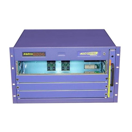
• The Ethernet MAC address of the switch • Symbols of safety certification Alpine 3804 Switch Front View The Alpine 3804 switch consists of the following components: • One 5-slot chassis with backplane • Four I/O module slots, labeled slots 1 through 4 •... -
Page 128: Front View Of The Alpine 3804 Switch With Sample I/O Modules Installed
Alpine 3800 Series Switch Chassis The Alpine 3804 switch can support the following number of ports and types of port configurations: • Up to 128 switched 10BASE-T/100BASE-TX Ethernet ports • Up to 96 switched 100BASE-FX Fast Ethernet ports • Up to 16 switched Gigabit Ethernet ports •... -
Page 129: Alpine 3804 Switch Rear View
Alpine 3804 Switch Rear View Figure 54 shows the rear view of the Alpine 3804 switch. Figure 54: Rear view of the Alpine 3804 switch Label 100-120 200-240 200-240 100-120 REMOVE SLIDE 45012 The rear view of the Alpine 3804 switch provides: •... -
Page 130: Front View Of The Alpine 3802 Switch With Sample I/O Modules Installed
Alpine modules: Alpine Ethernet I/O modules (green stripe) and Alpine Access I/O modules (silver stripe). • Auto—In auto mode, the switch determines if it is in standard or extended mode depending on the type of modules installed in the chassis or the slot preconfigurations. -
Page 131: Alpine 3802 Switch Rear View
Alpine 3802 Switch Rear View The Alpine 3802 switch comes in two versions: AC and DC . Figure 56 shows the rear view of the Alpine 3802 switch with AC power supplies installed. Figure 57 shows the rear view of the Alpine 3802 switch with DC power supplies installed. -
Page 132: Rear View Of The Alpine 3802 Switch With Dual Dc Power Supplies
NOTE Do not attempt to fix a failed power supply; power supplies are not user removable. Alpine 3802 switch power supplies must be installed or removed by trained service personnel only. Contact Extreme Networks Customer Support if you experience problems. -
Page 133: Alpine 3802 Software Enhancements
New Error Messages If you insert a module into the Alpine 3802 that is not allowed in a particular slot, the switch logs the error to the syslog. For example, if you insert a GM-WDMi module in slot 3, the switch logs an error. - Page 134 (for example, an FM-32Ti module) is installed or preconfigured in slot 2, the switch operates in standard mode. If an Alpine I/O module with a silver stripe (for example, a WM-4Ti module) is installed or preconfigured in slots 2 or 3, the switch operates in extended mode.
-
Page 135: Installing The Chassis
Alpine 3804 Alpine 3802 The Alpine 3808 and Alpine 3804 chassis are shipped with a preinstalled fan tray. For your safety, due to the increased weight of the chassis after components are installed and to prevent damage to the equipment, we strongly recommended that you install the power supply and modules after you mount the chassis in a rack. -
Page 136: Helper Bracket For Mounting The Alpine 3800 Series Chassis
Figure 60, Figure 61, and Figure 62. 6 After you secure the chassis, remove the helper bracket. Store it for future use, for example, if you need to remove the chassis. BDbrackt Extreme Networks Consolidated Hardware Guide... - Page 137 Figure 60: The Alpine 3808 chassis requires 8 screws to be securely mounted in a rack Helper bracket 38_rack8 Figure 61: The Alpine 3804 chassis requires 8 screws to be securely mounted in a rack Helper bracket 38_rack4 Extreme Networks Consolidated Hardware Guide...
-
Page 138: Grounding The Alpine 3800 Series Chassis
• One Panduit-style, standard two-hole barrel, copper compression lug • AWG, high strand-count copper wire cable, appropriate for your chassis — 8 AWG for the Alpine 3808 — 10 AWG for the Alpine 3804 — 14 AWG for the Alpine 3802 To ground the chassis: 1 Strip 0.5 inch (1.2 cm) of insulation from the appropriate AWG, high strand-count copper wire cable. - Page 139 3 To reduce weight and prevent possible equipment damage, use a # 1 Phillips screwdriver to remove the: • Power supply, SMMi, and I/O modules from the Alpine 3808 and Alpine 3804. • I/O modules from the Alpine 3802. For information about removing power supplies, see Chapter 8.
- Page 140 Alpine 3800 Series Switch Chassis Extreme Networks Consolidated Hardware Guide...
-
Page 141: Supported Power Supplies For The Alpine 3800 Series Switch
The power supplies for the Alpine 3808 are inserted into the front of the chassis. The power supplies for the Alpine 3804 are inserted into the lower rear of the chassis. The Alpine 3802 power supplies are preinstalled at the factory and are not user-removable. Table 37 describes the supported power supplies for the Alpine 3800 series switch. -
Page 142: Chapter 8 Alpine 3800 Series Switch Power Supplies
Installing the Alpine 3808 and the Alpine 3804 AC Power Supply This section describes how to install an AC power supply for either the Alpine 3808 or the Alpine 3804 switch. The Alpine 3802 switch power supply is preinstalled at the factory. The power supplies for the Alpine 3808 switch are inserted into the front of the chassis. -
Page 143: Ac Power Supply For The Alpine 3808 Switch
52. For more information about grounding the chassis, see “Grounding the Alpine 3800 Series Chassis” on page 138. You need the following tools and equipment to install the Alpine 3808 and the Alpine 3804 AC power supplies: • ESD-preventive wrist strap •... -
Page 144: Ac Power Supply For The Alpine 3804 Switch
Alpine 3800 Series Switch Power Supplies Figure 64: AC power supply for the Alpine 3804 switch Safety latch Handle WHEN INSTALLED IN 3804 THIS WAY UP 100-120 200-240 200-240 100-120 REMOVE SLIDE THIS 45012 SERVICE CAUTION When you install the power supply, open the ejector/injector lever and do not slam the power supply into the backplane. -
Page 145: Verifying A Successful Installation
I/O module LED activity. Removing the Alpine 3808 and the Alpine 3804 AC Power Supply You need the following tools and equipment to remove the Alpine 3808 and the Alpine 3804 AC power supplies: • ESD-preventive wrist strap •... -
Page 146: Supplying Power To The Alpine 3802 Ac Power Supply
6 If you are going to install a replacement power supply, follow the installation steps on page 142. 7 If there is a problem with the power supply that you removed, contact Extreme Networks for assistance. Do not attempt to fix a faulty power supply. Personal injury to yourself or others may occur. -
Page 147: Installing The Alpine 3808 And The Alpine 3804 Dc Power Supply
Selecting the Cabling Use the following guidelines when selecting cabling for the DC power supplies: • Each DC power supply requires 30 A (Alpine 3808) or 16.5 A (Alpine 3804) at -48 VDC nominal (or equivalent power between -40 and -70 VDC). -
Page 148: Dc Power Supply For The Alpine 3808 Switch
52. For more information about grounding the chassis, see “Grounding the Alpine 3800 Series Chassis” on page 138. You need the following tools and equipment to install the Alpine 3808 and the Alpine 3804 DC power supplies: • ESD-preventive wrist strap •... -
Page 149: Attaching The Cabling And Supplying Power
To attach the cable to the lugs, and then to the DC power supply, perform the following steps: Extreme Networks Consolidated Hardware Guide Installing the Alpine 3808 and the Alpine 3804 DC Power Supply Ejector/ injector Handle... -
Page 150: Alpine 3808 Dc Power Supply With Cables
Figure 67 and Figure 68. Figure 67: Alpine 3808 DC power supply with cables -48V WHEN Figure 68: Alpine 3804 DC power supply with cables REMOVE SLIDE CAUTION Ensure that no copper is visible between the lug and the cable insulation. -
Page 151: Verifying A Successful Installation
I/O module LED activity. Removing the Alpine 3808 and the Alpine 3804 DC Power Supply You need the following tools and equipment to remove the Alpine 3808 and the Alpine 3804 DC power supplies: • ESD-preventive wrist strap •... -
Page 152: Supplying Power To The Alpine 3802 Dc Power Supply
8 If you are going to install a replacement power supply, follow the installation steps on page 147. 9 If there is a problem with the power supply that you removed, contact Extreme Networks for assistance. Do not attempt to fix a faulty power supply. Personal injury to yourself or others may occur. -
Page 153: Selecting The Cabling
NOTE Alpine 3802 power supplies must be removed and replaced by personnel that have been trained by Extreme Networks and in accordance with all local and national electrical codes. Selecting the Cabling Use the following guidelines when selecting cabling for the DC power supplies: •... - Page 154 Alpine 3800 Series Switch Power Supplies If the switch passes the POST, the MGMT LED blinks at a slow rate (one blink per second). If the switch fails the POST, the MGMT LED shows a solid yellow light. NOTE See Chapter 9, “Alpine 3800 Series Switch Management Module” for more information about switch management module LED activity and Chapter 10, “Alpine 3800 Series I/O Modules”...
-
Page 155: Alpine 3800 Series Switch Management Module
Management Module (SMMi). The Switch Management Module (SMMi) is responsible for upper-layer protocol processing and switch management functions in the Alpine 3808 and Alpine 3804 chassis. The SMMi can store two ExtremeWare software images (version 6.0 or later) and two switch configurations. -
Page 156: Smmi Memory
The SMMi has two 144-pin SODIMM sockets, and ships with two 128 MB SODRAM modules installed, as shown in Figure 71. NOTE The SMMi supports only the SODIMMs that are supplied by Extreme Networks. Figure 71: SMMi SODIMM sockets NOTE See “Adding SODIMMs to the SMMi Module”... -
Page 157: Installing Smmi Modules
2 Attach the ESD strap that is provided to your wrist and connect the metal end to the ground receptacle that is located on the top-right corner of the switch front panel. 3 Remove the blank faceplate from the slot to make room for the module, if applicable. -
Page 158: Verifying The Smmi Module Installation
For more information about SMMi module LED activity, see “SMMi LEDs” on page 156. Adding SODIMMs to the SMMi Module The SMMi supports only SODIMMs from Extreme Networks. To add a SODIMM to the SMMi: 1 Attach an ESD strap to your wrist and connect the metal end to the ground receptacle that is located on the top-right corner of the switch front panel. -
Page 159: Removing Sodimms From The Smmi Module
1 Attach the ESD strap that is provided to your wrist and connect the metal end to the ground receptacle that is located on the top-right corner of the switch front panel. 2 Use a #2 Phillips screwdriver to unscrew the two captive screws. - Page 160 Alpine 3800 Series Switch Management Module Extreme Networks Consolidated Hardware Guide...
-
Page 161: Alpine 3800 Series I/O Modules
Specifications.” Configuring I/O Modules No configuration information is stored on the I/O modules; configuration information is stored on the SMMi for the Alpine 3808 and 3804 chassis and the integrated Switch Management Module in the Alpine 3802 chassis. NOTE There is a slight difference in appearance between Alpine I/O modules. Alpine Ethernet I/O modules have a green stripe along the side of the module. - Page 162 If you pre-configure a slot for a specific module type, and then insert a different type of module, the module reverts to its default configuration. NOTE See the ExtremeWare Software User Guide and the ExtremeWare Command Reference Guide for more information about configuring I/O modules. Extreme Networks Consolidated Hardware Guide...
-
Page 163: Gm-4Ti Module
The GM-4Xi module has four GBIC-based Gigabit Ethernet ports. All Gigabit Ethernet ports on this module use standard GBIC connectors and support 1000BASE-SX, 1000BASE-LX, and 1000BASE-LX70. The default configuration of the GM-4Xi module is as follows. All ports: Extreme Networks Consolidated Hardware Guide 100/1000 Mbps ports Gigabit Ethernet ports... -
Page 164: Gbic Types And Maximum Distances
(1550 nm optical window) Category 5 UTP cable *Extreme Networks proprietary. Connections between two Extreme Networks 1000BASE-LX interfaces can use a maximum distance of 10,000 meters. If you have an Alpine 3800 series switch populated with a GM-4Xi module, do one of the following: •... -
Page 165: Gm-4Si Module
• Are added to the default VLAN as untagged. • Inherit the properties of the default VLAN (protocol type, VLANid, and so forth). • Operate in autonegotiation mode. Extreme Networks Consolidated Hardware Guide 1000 Mbps ports Configuring I/O Modules 38_GM4S... -
Page 166: Gm-Wdmi Module
The GM-WDMi module transmits bi-directionally on the fiber cable and then multiplexes these wavelengths over the single-mode optical fiber. Typical Maximum -4 dBm 850 nm 860 nm 0 dBm 860 nm 4 Gbps port 38_GMWDM Extreme Networks Consolidated Hardware Guide... - Page 167 General Total system budget Extreme Networks recommends that you reserve 3 dB for losses due to cable splices, connectors, and operating margin. Table 46 describes the cable attenuation, cable budget, and operating distance for a variety of cable attentuation ratings for the GM-WDMi module.
-
Page 168: Fm-32Ti Module
For information about the LEDs and their activity on the FM-32Ti module, see “I/O Module LEDs” on page 176. FM-24Ti Module Figure 79 shows the FM-24Ti module. Figure 79: FM-24Ti module Module status LED Port status LEDs 10/100 Mbps ports 10/100 Mbps ports 38_FM32T 38_FM24T Extreme Networks Consolidated Hardware Guide... - Page 169 • Module status • Port status For information about the LEDs and their activity on the FM-24Ti module, see “I/O Module LEDs” on page 176. Extreme Networks Consolidated Hardware Guide Cable Min Length Shielded trunk cable with 25 CAT5 twisted pairs...
-
Page 170: Fm-24Sfi Module
1510 nm General Total system budget LEDs The FM-24SFi module has the following LEDs: • Module status • Port status 100 Mbps ports with status LEDs Typical FM-24SFi Maximum -14 dBm -8 dBm 11 dBm Extreme Networks Consolidated Hardware Guide... -
Page 171: Fm-24Mfi Module
Optical output power Center wavelength Receiver Optical input power sensitivity Optical input power maximum Operating wavelength General Total system budget Extreme Networks Consolidated Hardware Guide 100 Mbps ports with status LEDs Minimum Typical -20 dBm 1310 nm -31 dBm 1310 nm... -
Page 172: Fm-8Vi Module
The connector on the FM-8Vi requires a male terminated RJ-21 cable. The FM-8Vi uses eight of the twenty-five pairs in the cable. Because the RJ-21 standard was established for telecommunications, one wire of each pair is designated as the tip side and the other wire is designated as the ring side. Extreme Networks Consolidated Hardware Guide... - Page 173 However, the VDSL ports on the FM-8Vi connect to the Mogul-100 in such a way that the Ethernet port on the Mogul-100 behaves as though it is located on the Alpine switch. When you configure a port on the FM-8Vi, you are configuring the Ethernet port on the Mogul-100. For example, when you add port 2 on the FM-8Vi to a VLAN, the Ethernet port on the Mogul-100 connected to port 2 of the FM-8Vi now belongs to that VLAN.
-
Page 174: Wm-4T1I Module
You must ground the Alpine 3800 series chassis to ensure safe operation of the WM-4T1i module. For information about grounding requirements for the Alpine 3800 series chassis, see “Grounding the Alpine 3800 Series Chassis” on page 138. LEDs The WM-4T1i module has the following LEDs: • Module status • Port status Extreme Networks Consolidated Hardware Guide... -
Page 175: Wm-4E1I Module
The WM-4E1i module requires ExtremeWare software version 6.1.5 or later and BootROM 6.5 or later. For more information about software requirements and WM-4E1i module configuration, see the ExtremeWare Software User Guide and the ExtremeWare Command Reference Guide. Extreme Networks Consolidated Hardware Guide... -
Page 176: Wm-1T3I Module
Access I/O modules with the silver stripe (for example, the WM-4T1i, WM-4E1i, and WM-1T3i I/O modules). Table 51: Alpine I/O module LEDs (green stripe) Color Indicates Status Green Normal operation Amber Disabled 10/100 Mbps ports 38_WM1T3i Extreme Networks Consolidated Hardware Guide... -
Page 177: Installing I/O Modules
Installing I/O Modules You can insert I/O modules at any time, without causing disruption of network services. You need the following tools and equipment to install an I/O module: • ESD-preventive wrist strap Extreme Networks Consolidated Hardware Guide Indicates Link up Disabled... - Page 178 Slide the module into the appropriate slot of the chassis (slots 1 through 8 in the Alpine 3808, slots 1 through 4 in the Alpine 3804, or slots 1 through 3 in the Alpine 3802), until it makes contact with the backplane.
-
Page 179: Verifying The I/O Module Installation
All Alpine 3800 series modules (SMMi and I/O modules) are hot-swappable. You do not need to power off the system to remove a module. You need the following tools and equipment to remove an I/O module: Extreme Networks Consolidated Hardware Guide Verifying the I/O Module Installation command to show slot <slot number>... - Page 180 1 Attach the ESD strap that is provided to your wrist and connect the metal end to the ground receptacle that is located on the top-right corner of the switch front panel. 2 Use a #2 Phillips screwdriver to unscrew the two captive screws.
-
Page 181: Alpine 3800 Series Switch Fan Tray
• Alpine 3804 Fan Tray on page 182 • Alpine 3802 Fan Tray on page 182 • Removing the Alpine 3808 or Alpine 3804 Fan Tray on page 183 • Installing the Alpine 3808 or Alpine 3804 Fan Tray on page 184... -
Page 182: Alpine 3804 Fan Tray
Do not cover or obstruct the fan ventilation holes at the rear of the unit. Doing so can result in overheating and possible damage to the Alpine 3804 switch. Thermal sensors will shut down the Alpine 3804 switch if the internal temperature exceeds 60 degrees Celsius. -
Page 183: Removing The Alpine 3808 Or Alpine 3804 Fan Tray
Removing the Alpine 3808 or Alpine 3804 Fan Tray Alpine 3808 and Alpine 3804 fan trays are hot-swappable. You do not need to turn off power to an Alpine 3808 or Alpine 3804 switch to remove a fan tray. You need the following tools and equipment to remove a fan tray: •... -
Page 184: Installing The Alpine 3808 Or Alpine 3804 Fan Tray
Finger grips Installing the Alpine 3808 or Alpine 3804 Fan Tray Alpine 3808 and Alpine 3804 fan trays are hot-swappable. You do not need to turn off power to an Alpine 3808 or Alpine 3804 switch to install a fan tray. - Page 185 CAUTION Only trained service personnel should perform service to Alpine 3808 or Alpine 3804 fan trays. Before installing or removing any components, or carrying out any maintenance procedures, see Appendix A. To install the fan tray in the Alpine 3808 or Alpine 3804 switch: 1 Attach the ESD strap that is provided to your wrist and connect the metal end to the ground receptacle that is located on the top-right corner of the switch front panel.
- Page 186 Alpine 3800 Series Switch Fan Tray Extreme Networks Consolidated Hardware Guide...
-
Page 187: Part 5 Blackdiamond Switch
Part 5 BlackDiamond Switch... -
Page 189: Blackdiamond 6800 Series Switch Overview
This section describes the features of the BlackDiamond family of switches. If the information in the release notes differs from the information in this guide, follow the release notes. For more information about configuring the switch, refer to the ExtremeWare Software User Guide and The ExtremeWare Command Reference Guide. -
Page 190: Port Connections
Avoid direct eye exposure to beam. Table 53: Port configurations available on BlackDiamond I/O modules Ethernet Ports 10BASE-T/ 100BASE-T/ Module 100BASE-TX 1000BASE-T G8Ti G8Xi G12SXi WDMi 10GLRi F32T F48Ti F96Ti F32Fi GBIC 1000BASE-SX 100BASE-FX OTHER 1 10-Gbps 1 10GBASE-LR Extreme Networks Consolidated Hardware Guide... -
Page 191: Switch Components
The BlackDiamond 6816 chassis only supports modules and power supplies with an “i” in their name, such as the MSM64i. BlackDiamond 6808 Switch The BlackDiamond 6808 switch consists of the following components: • One 10-slot chassis with backplane Extreme Networks Consolidated Hardware Guide 100BASE-T/ 1000BASE-T GBIC 1000BASE-SX... -
Page 192: Blackdiamond 6804 Switch
A passive backplane is important because it increases the reliability of the switch. The I/O modules treat the backplane as one logical connection and use the same load sharing (trunking) algorithm as the front facing ports to distribute the switch traffic. There... -
Page 193: Packet Switching And Routing
MSM64i modules that are installed in the switch. For example, if you install an F48Ti module, it has eight Gigabit Ethernet links to the switch backplane. If you have a BlackDiamond 6816 and install four MSM64i modules, each module receives two of the eight Gigabit Ethernet links. - Page 194 BlackDiamond 6800 Series Switch Overview Extreme Networks Consolidated Hardware Guide...
-
Page 195: Blackdiamond 6800 Series Switch Chassis
BlackDiamond 6800 Series Switch Chassis There are three models in the BlackDiamond 6800 series: The BlackDiamond 6816 switch, the BlackDiamond 6808 switch, and the BlackDiamond 6804 switch. This chapter describes: • BlackDiamond 6800 Series Architecture on page 195 • Installing the Chassis on page 204 •... - Page 196 BlackDiamond 6800 Series Switch Chassis The BlackDiamond 6816 switch can support the following number of ports and types of port configurations: • Up to 1344 switched 10BASE-T/100BASE-TX Ethernet ports • Up to 448 switched 100BASE-FX Fast Ethernet ports • Up to 192 switched Gigabit Ethernet ports •...
-
Page 197: Front View Of The Blackdiamond 6816 Switch With Sample I/O Modules
Figure 89: Front view of the BlackDiamond 6816 switch with sample I/O modules ESD wrist strap connector I/O module slots MSM module slots I/O module slots Power supplies Extreme Networks Consolidated Hardware Guide BlackDiamond 6800 Series Architecture BD_6816s... -
Page 198: Blackdiamond 6816 Switch Rear View
• The chassis serial number • The Ethernet MAC address of the switch • Symbols of safety certification Figure 90 shows the rear view of the BlackDiamond 6816 switch. Figure 90: Rear view of the BlackDiamond 6816 switch Grounding studs... -
Page 199: Blackdiamond 6808 Switch Front View
• One fan tray (accessed from the rear of the unit) • One electromagnetic discharge (ESD) wrist strap connector The BlackDiamond 6808 switch can support the following number of ports and types of port configurations: • Up to 672 switched 10BASE-T/100BASE-TX Ethernet ports •... -
Page 200: Front View Of The Blackdiamond 6808 Switch With Sample I/O Modules
BlackDiamond 6800 Series Switch Chassis Figure 91: Front view of the BlackDiamond 6808 switch with sample I/O modules I/O module slots ESD wrist strap connector POWER Power supplies V-50/60Hz 200-240V, 15A MSM module slots I/O module slots 50015 50015 51040... -
Page 201: Blackdiamond 6808 Switch Rear View
• The chassis serial number • The Ethernet MAC address of the switch • Symbols of safety certification Figure 92 shows the rear view of the BlackDiamond 6808 switch. Figure 92: Rear view of the BlackDiamond 6808 switch Fan tray... -
Page 202: Blackdiamond 6804 Switch Front View
• One fan tray (accessed from the front of the unit) • One electromagnetic discharge (ESD) wrist strap connector The BlackDiamond 6804 switch can support the following number of ports and types of port configurations: • Up to 384 switched 10BASE-T/100BASE-TX Ethernet ports •... -
Page 203: Blackdiamond 6804 Switch Rear View
Figure 93: Front view of the BlackDiamond 6804 switch with sample I/O modules ESD receptacle module slots module slots POWER Power supplies V-50/60Hz 200-240V, 15A BlackDiamond 6804 Switch Rear View The rear of the BlackDiamond 6804 switch provides: • The chassis serial number •... -
Page 204: Installing The Chassis
NOTE Mount the chassis in a rack before installing any switch components. Grounding studs 6804_rr... -
Page 205: Rack Installation
Keep the sheet metal plates on the chassis while you insert the chassis into the rack. 4 Have a minimum of two people lift and place the empty chassis on the helper bracket and slowly guide the chassis into the rack. Extreme Networks Consolidated Hardware Guide Installing the Chassis BDbrackt... - Page 206 NOTE To ensure the system meets the NEBS GR-63-CORE Zone 4 earthquake requirements, we recommend the use of a welded steel seismic rack, such as Hendry Telephone Products (www.hendry.com) model: 0GS136. Extreme Networks Consolidated Hardware Guide...
-
Page 207: Securing The Blackdiamond 6816 Chassis In A Rack
Figure 96: Securing the BlackDiamond 6816 chassis in a rack Extreme Networks Consolidated Hardware Guide BD_rack16 Installing the Chassis... -
Page 208: Securing The Blackdiamond 6808 Chassis In A Rack
BlackDiamond 6800 Series Switch Chassis Figure 97: Securing the BlackDiamond 6808 chassis in a rack Figure 98: Securing the BlackDiamond 6804 chassis in a rack 6804rack Extreme Networks Consolidated Hardware Guide... -
Page 209: Grounding The Blackdiamond 6800 Series Chassis
• A minimum of two people to help remove the chassis from the rack To uninstall the chassis from a rack: 1 Unplug the power cable from the outlet and then from the switch before you attempt to remove the chassis components and the chassis from the rack. - Page 210 5 Have a minimum of two people gently remove the chassis from the rack and place it on a secure, flat surface with the front of the chassis facing you. 6 Unscrew the helper bracket and remove it from the rack. Extreme Networks Consolidated Hardware Guide...
-
Page 211: Blackdiamond 6800 Series Switch Power Supplies
BlackDiamond 6804 chassis. To increase switch reliability, you can install additional power supplies as needed. If you have three or more power supplies installed in a BlackDiamond 6816 switch or two or more power supplies installed in a BlackDiamond 6808 or BlackDiamond 6804 switch, you can remove one of the power supplies without turning off power to the chassis. -
Page 212: 220 Vac Power Supplies
BlackDiamond 6808, and two modules in the BlackDiamond 6804 are powered on. The BlackDiamond switch does not support installing a combination of the old 220 VAC PSUs (part number 50012) with the new iPower 220 VAC PSUs (part number 50021) in the same chassis. -
Page 213: 110 Vac Power Supplies
Table 58 describes the LED activity on the 110 VAC power supply Table 58: 110 VAC power supply LED activity Color AC In Green Amber Extreme Networks Consolidated Hardware Guide Indicates Input voltage is 220 V Input voltage is less than 180 V No input power All DC outputs are operational... -
Page 214: Dc Power Supplies
Input voltage is within range Amber Input voltage is outside of range Input voltage is below 12 V DC OUT DC IN POWER DC OUT DC IN 50022 SINGLE DC PSU -48V -48V RET 48V, 60A BD_DCpsx Extreme Networks Consolidated Hardware Guide... -
Page 215: Installing A Blackdiamond 6800 Series Power Supply
2 If there is a blank faceplate covering the power supply bay, remove it and save it for future use. 3 For the BlackDiamond 6816 switch, ensure that the power supply is right side up, as shown in Figure 102, and the locking handle is open. -
Page 216: Installing An Ac Power Supply In A Blackdiamond 6808 Or A Blackdiamond 6804
Figure 102: Installing a DC power supply in a BlackDiamond 6816 Figure 103: Installing an AC power supply in a BlackDiamond 6808 or a BlackDiamond 6804 POWER DC OUT AC IN 50021 V-50/60Hz 200-240V, 15A BD_034 BD_033 Extreme Networks Consolidated Hardware Guide... - Page 217 If you have a DC power supply, remove the plexiglass cover, attach the power cables, and turn the on/off switch to the on position. See “Attaching the DC Cabling” on page 220 for more information about how to attach the DC cabling to the power supply.
-
Page 218: Ac Power Cable And Plug
POWER AC Power Cable and Plug Use the appropriate AC power cable and plug for your switch and your location. See “Wiring Closet Considerations” on page 43 for more information about the types of power cords to use. Figure 106 shows the BlackDiamond 6800 series 220 VAC power cable and plug. -
Page 219: Selecting The Dc Cabling
DC power supply. Figure 108 shows the specifications of the lug that is used to connect the DC power cable to the DC power supply. Extreme Networks Consolidated Hardware Guide Installing a BlackDiamond 6800 Series Power Supply Wider prong... -
Page 220: Attaching The Dc Cabling
(+) and negative (–) studs extend 0.9 inch high-strand-count Terminal crimp Area for heat-shrink 0.37 in. tubing (0.94cm) ” or ” flathead screwdriver, to 20 in-lbs of torque. The DC_lug 4 AWG, conductor BD_021 Extreme Networks Consolidated Hardware Guide... -
Page 221: Verifying A Successful Installation
2 Completely remove the power supply cable(s) from the wall outlet and then from the power supply. If you have a DC power supply, turn the on/off switch to the off position and remove the power cables. -
Page 222: Removing Blackdiamond 6816 Dc Power Supplies
BlackDiamond 6800 Series Switch Power Supplies Figure 110: Removing BlackDiamond 6816 DC power supplies Figure 111: Removing BlackDiamond 6808 or BlackDiamond 6804 220 VAC power supplies POWER DC OUT AC IN POWER 50021 50021 BD_029 DC OUT AC IN BD_028 Extreme Networks Consolidated Hardware Guide... - Page 223 Do not handle the power supply using the DC output bus bars. 6 Leave the ESD strap permanently connected to the chassis so that it is always available when you need to handle ESD-sensitive components. Extreme Networks Consolidated Hardware Guide Removing a BlackDiamond 6800 Series Power Supply...
- Page 224 BlackDiamond 6800 Series Switch Power Supplies Extreme Networks Consolidated Hardware Guide...
-
Page 225: Blackdiamond 6800 Series Management Switch Module
Read the information in this chapter thoroughly before you attempt to install or remove the BlackDiamond Management Switch Fabric Module (MSM64i). The Management Switch Fabric Module (MSM64i) is the internal switch fabric for data that is being sent between I/O modules. One MSM64i is required for switch operation; however, adding more MSM64i modules increases both reliability and throughput. -
Page 226: Msm64I Activity
Packet handling is distributed among the CPUs of all installed MSM64i modules. When you save the switch configuration, it is saved to all MSM64i modules. If you download a new ExtremeWare image, the image is downloaded to all MSM64i modules. -
Page 227: Msm64I Memory
• When the BlackDiamond 6800 series switch boots with a single MSM64i (regardless of the slot position), it is selected as the master. If additional MSM64i modules are added to the switch after powered on, the added MSM64i modules become the slaves. MSM64i modules that operate as slaves can be inserted and removed without disrupting network services. -
Page 228: Msm64I Leds
To reset the critical software error LED (amber ERR LED), use the reboot the switch. If you continue to have critical software errors, or the ERR LED is amber after the command and a switch reboot, contact Extreme Networks Customer Support. -
Page 229: Installing Msm64I Modules
2 Attach the ESD strap that is provided to your wrist and connect the metal end to the ground receptacle that is located on the top-left corner of the switch front panel. 3 Remove the blank faceplate from the slot to make room for the module, if applicable. -
Page 230: Msm64I Prior To Insertion In A Blackdiamond 6808
To secure the module, tighten the two screws with a #1 Phillips screwdriver. NOTE Tighten the screws of this module before you insert additional modules. Otherwise, you might unseat modules that you have not secured. Extreme Networks Consolidated Hardware Guide... -
Page 231: Verifying The Msm64I Module Installation
MSM64i to the slave MSM64i. CAUTION Depending on the size and complexity of your network, you should install and configure a slave MSM64i module when there will be minimal network disruption. You may need to reboot your switch after you use the synchronize 6 Store the module packaging for future use. -
Page 232: Removing A Sodimm From The Msm64I Module
1 Attach an ESD strap to your wrist and connect the metal end to the ground receptacle that is located on the top-left corner of the switch front panel. 2 To loosen the module, unscrew the screws with a #1 Phillips screwdriver. EW_SODMs Extreme Networks Consolidated Hardware Guide... - Page 233 5 Leave the ESD strap permanently connected to the chassis so that it is always available when you need to handle ESD-sensitive components. To remove additional MSM64i modules, repeat steps 1 through 4. Extreme Networks Consolidated Hardware Guide Removing MSM64i Modules...
- Page 234 BlackDiamond 6800 Series Management Switch Module Extreme Networks Consolidated Hardware Guide...
-
Page 235: Blackdiamond 6800 Series I/O Modules
BlackDiamond I/O modules consist of a printed circuit board mounted on a metal panel that acts as the insertion vehicle in a BlackDiamond 6800 series switch. The module carrier also includes ejector/injector levers and captive retaining screws at each end of the module front panel. - Page 236 BlackDiamond 6800 Series I/O Modules NOTE See the ExtremeWare Software User Guide and the ExtremeWare Command Reference Guide for more information about configuring I/O modules. Extreme Networks Consolidated Hardware Guide...
-
Page 237: G8Ti Module
The G8Ti module has the following LEDs: • Module status • Port status • Port speed For information about the LEDs and their activity on the G8Ti module, see “I/O Module LEDs” on page 271. Extreme Networks Consolidated Hardware Guide... -
Page 238: G8Xi Module
The G8Xi module supports any of the following GBICs: • 1000BASE-SX • 1000BASE-LX • 1000BASE-LX70 • ZX GBIC • LX100 GBIC • UTP GBIC GBIC Media Types and Distances. Table 64 describes the media types and associated maximum distances for each GBIC type. Extreme Networks Consolidated Hardware Guide... - Page 239 (1550 nm optical window) LX100 (1550 nm optical window) *Extreme Networks proprietary. Connections between two Extreme Networks 1000BASE-LX interfaces can use a maximum distance of 10,000 meters. NOTE For more information about the supported GBIC types, see “GBIC Specifications” on page 32.
-
Page 240: G12Sxi Module
For information about the LEDs and their activity on the G12SXi module, see “I/O Module LEDs” on page 271. Software Requirements The G12SXi module requires that you load ExtremeWare version 6.1.4 or later on the switch. Extreme Networks Consolidated Hardware Guide... -
Page 241: Wdmi Module
Parameter Transmitter Optical output power Channel 1 wavelength Channel 2 wavelength Channel 3 wavelength Channel 4 wavelength Receiver Optical input power sensitivity Extreme Networks Consolidated Hardware Guide BD_WDMi Minimum Typical -5 dBm -3 dBm 1495 nm 1501 nm 1515 nm... - Page 242 Fiber Optic Cable Back reflection Extreme Networks recommends that you reserve 3 dB for losses due to cable splices, connectors, and operating margin. Table 66 describes the cable attenuation, cable budget, and operating distance for a variety of cable attentuation ratings for the WDMi module...
-
Page 243: 10Glri Module
Table 67 summarizes the optical parameters for the 10GLRi module. Table 67: 10GLRi optical parameters Parameter Minimum launch power Maximum receiver sensitivity Minimum extinction ratio Minimum distance Extreme Networks Consolidated Hardware Guide Port status LED 10 Gbps port XM_042 Value -6.2 dBm -12.6 dB 3.5 dB... - Page 244 10m <cost> 100m <cost> 1g <cost> 10g <cost> Where specifies the interface cost. <cost> The default cost settings for each interface are: • 10 Mbps—10 • 100 Mbps—5 • 1 Gbps—4 • 10 Gbps—2 Extreme Networks Consolidated Hardware Guide...
-
Page 245: F48Ti Module
For information about the LEDs and their activity on the F48Ti module, see “I/O Module LEDs” on page 271. Software Requirements The F48Ti module requires that you load ExtremeWare version 6.1.4 or later on the switch. Extreme Networks Consolidated Hardware Guide 52011... -
Page 246: F96Ti Module
Port 5 Port 4 Port 3 Port 2 Port 1 Spare Port 12 Port 11 Port 10 Port 9 Port 8 Port 7 Port 6 Port 5 Port 4 Port 3 Port 2 Port 1 BD_037 Extreme Networks Consolidated Hardware Guide... -
Page 247: Connector Pinouts For The Rj-21 Port
RxD (-) TxD (-) RxD (-) TxD (-) RxD (-) TxD (-) Extreme Networks Consolidated Hardware Guide RJ-45 Pin Numbers 2, 6, 1, 3 2, 6, 1, 3 2, 6, 1, 3 2, 6, 1, 3 2, 6, 1, 3... - Page 248 For information about the module status LED and its activity on the F96Ti module, see “I/O Module LEDs” on page 271. Output Signal RxD (+) TxD (+) Min Length Max Length 100 m XM_046 Max Torque 4 in-lbs Extreme Networks Consolidated Hardware Guide...
-
Page 249: F32Fi Module
For information about the LEDs and their activity on the F32Fi module, see “I/O Module LEDs” on page 271. Software Requirements The F32Fi module requires that you load ExtremeWare version 6.1.8 or later and BootROM 6.5 or later on the switch. Extreme Networks Consolidated Hardware Guide Configuring I/O Modules... -
Page 250: P3Csi, P3Cmi, P12Csi, And P12Cmi Modules
The P3cSi and the P12cSi modules support single mode fiber-optic cable only, and the P3cMi and the P12cMi modules support multimode fiber-optic cable only. These modules connect the switch to a SONET infrastructure that is used by metropolitan area service providers and operators of server co-location networks. -
Page 251: Optical Interface Specifications For The Pos Modules
In the first application, the metropolitan area network service provider can build service network sites in various cities, then use PoS modules in a BlackDiamond 6800 series switch to connect those cities to a carrier’s SONET infrastructure. In the second application, operators of server co-location networks can use PoS modules in BlackDiamond 6800 series switches to create a SONET-based connection between server co-location sites. - Page 252 Service Ports. The PoS modules are equipped with two front-panel service ports: one port is a subminiature DB-9 connector; the other is a micro HD-15 connector (see Figure 129). Both ports are reserved for use only by Extreme Networks technical support personnel for diagnostic purposes. Extreme Networks Consolidated Hardware Guide...
-
Page 253: Showing The Components And Leds Of The Pos Module
— MultiProtocol Label Switching Control Protocol (MPLSCP) — OSI Network Layer Control Protocol (OSINLCP) — Extreme Discovery Protocol Control Protocol (EDPCP) • Efficient support for IP routing over SONET via IPCP • Support for Transparent LAN Services (TLS) over SONET via BCP •... - Page 254 The use of PPP over SONET links is commonly referred to as Packet over SONET, or PoS. The Extreme Networks implementation of PPP for the PoS module provides support for the following protocols in the PPP suite:...
- Page 255 Jumbo frames are Ethernet frames that are larger than 1522 bytes, including four bytes used for the cyclic redundancy check (CRC). Extreme products that use the “i” chipset support switching and routing of jumbo frames at wire-speed on all ports.
- Page 256 You can also control whether traffic switched to the protection line is automatically switched back to the working line when it is restored to service. The Extreme Networks implementation supports network configurations where: • Working and protection lines are terminated in the same PoS module.
- Page 257 PoS modules, consult your release notes. PoS modules installed in a BlackDiamond chassis require at least one BlackDiamond Ethernet I/O module also installed in the chassis in order to operate correctly. Extreme Networks Consolidated Hardware Guide...
-
Page 258: Arm
• Processing the frames. • Transmitting the frames back into the switch fabric which then sends them to the appropriate I/O module. A maximum of four ARM modules can be placed in a BlackDiamond 6800 series switch at any one time. Physical Description This section describes the components and the LEDs of the ARM module, as shown in Figure 131. -
Page 259: Showing The Components And Leds Of The Arm Module
Service Ports. The ARM module is equipped with two front-panel service ports: one port is a DB-9 connector; the other is a micro HD-15 connector (see Figure 131). Both ports are reserved for use only by Extreme Networks technical support personnel for diagnostic purposes. Figure 131: Showing the components and LEDs of the ARM module... - Page 260 Each ARM IP routing database provides an aggregate IP forwarding throughput of up to 4 Gbps. The total forwarding throughput for a single BlackDiamond chassis can be scaled up to 16 Gbps by adding up to four ARM modules. ARMs interface to the BlackDiamond switch fabric via four 1 Gbps internal links.
-
Page 261: Mpls Module
• Transmitting the frames back into the switch fabric which then sends them to the appropriate I/O module. A maximum of four MPLS modules can be placed in a BlackDiamond 6800 series switch at any one time. Extreme Networks Consolidated Hardware Guide... - Page 262 Service Ports. The MPLS module is equipped with two front-panel service ports: one port is a subminiature DB-9 connector; the other is a micro HD-15 connector (see Figure 133). The ports are reserved for use only by Extreme Networks technical support personnel for diagnostic purposes. Extreme Networks Consolidated Hardware Guide...
-
Page 263: Showing The Components And Leds Of The Mpls Module
FECs include an IP prefix, a host address, or a VLAN ID. The label concept in MPLS is analogous to other connection identifiers, such as an ATM VPI/VCI or a Frame Relay DLCI. Extreme Networks Consolidated Hardware Guide Module status LED... - Page 264 VPN scalability. IP Unicast Forwarding. IP unicast packets are forwarded in the MPLS module using the longest prefix match algorithm. IP unicast forwarding is required to switch packets at ingress or upon egressing an MPLS network domain.
- Page 265 MPLS module, consult your release notes. MPLS modules installed in a BlackDiamond chassis require at least one BlackDiamond Ethernet I/O module also installed in the chassis in order to operate correctly. Extreme Networks Consolidated Hardware Guide...
-
Page 266: A3Csi And A3Cmi Modules
Enterprise ATM network and an Ethernet backbone. In the first application, the metropolitan area network service provider can build service network sites in various cities, then use ATM modules in a BlackDiamond 6800 series switch to connect those cities to a carrier’s ATM infrastructure. -
Page 267: Optical Interface Specifications For The Atm Modules
• Two high-performance network processors • A GPP subsystem The network processors are programmable devices that participate with the Extreme “i” chipset to support expanded functionality, features, and flexibility. The GPP subsystem handles system control and I/O module management functions. The GPP subsystem resides outside of the I/O module data path to optimize performance. -
Page 268: Showing The Components And Leds Of The Atm Module
The ATM module is equipped with two front-panel service ports: one port is a DB-9 connector; the other is a micro HD-15 connector (see Figure 135). Both ports are reserved for use only by Extreme Networks technical support personnel for diagnostic purposes. - Page 269 Jumbo frames are Ethernet frames that are larger than 1522 bytes, including four bytes used for the cyclic redundancy check (CRC). Extreme products that use the “i” chipset support switching and routing of jumbo frames at wire-speed on all ports.
- Page 270 VID tables: one table is used in the ingress direction; the other is used in the egress direction. Each of the tables enables an input VID to be mapped to an output VID. This feature is useful in reconciling policy differences at the boundary between the customer and the service provider. Extreme Networks Consolidated Hardware Guide...
-
Page 271: I/O Module Leds
Amber blinking DIAG Amber blinking Amber Port x Green Green blinking Amber blinking Extreme Networks Consolidated Hardware Guide Indicates Normal operation Configuration error, code version error, diagnostic failure, or other severe module error No power Normal operation Diagnostics in progress... -
Page 272: Installing I/O Modules
You need the following tools and equipment to install an I/O module: • ESD-preventive wrist strap • # 1 Phillips screwdriver • I/O module • Appropriate type of cable for the I/O module you plan to install Extreme Networks Consolidated Hardware Guide... - Page 273 2 Attach the ESD strap that is provided to your wrist and connect the metal end to the ground receptacle that is located on the top-left corner of the switch front panel. 3 Remove the blank faceplate from the slot to make room for the module, if applicable.
-
Page 274: Verifying The I/O Module Installation
For more information about slot status information, see the ExtremeWare Software User Guide and the ExtremeWare Command Reference Guide. command to show slot <slot number> (where <slot> is the show slot <slot> also displays that show slot <slot> Extreme Networks Consolidated Hardware Guide... -
Page 275: Removing I/O Modules
1 Attach the ESD strap that is provided to your wrist and connect the metal end to the ground receptacle that is located on the top-left corner of the switch front panel. 2 Use a #1 Phillips screwdriver to unscrew the two captive screws. - Page 276 BlackDiamond 6800 Series I/O Modules Extreme Networks Consolidated Hardware Guide...
-
Page 277: Chapter 17 Blackdiamond 6800 Series Switch Fan Tray
ExtremeWare monitors the fan trays in the BlackDiamond 6816 switch for failure and overheat conditions. All fan failures and over temperature events cause the switch to send alerts to the network management station or to the switch log. See the ExtremeWare Software User Guide for more information on switch monitoring. -
Page 278: Blackdiamond 6808 Fan Tray
ExtremeWare monitors the fan trays in the BlackDiamond 6808 switch for failure and overheat conditions. All fan failures and over temperature events cause the switch to send alerts to the network management station or to the switch log. See the ExtremeWare Software User Guide for more information on switch monitoring. -
Page 279: Blackdiamond 6804 Fan Tray
ExtremeWare monitors the fan trays in the BlackDiamond 6804 switch for failure and overheat conditions. All fan failures and over temperature events cause the switch to send alerts to the network management station or to the switch log. See the ExtremeWare Software User Guide for more information on switch monitoring. -
Page 280: Removing A Blackdiamond 6800 Series Fan Tray
2 For the BlackDiamond 6816 switch or the BlackDiamond 6804 switch, use a #1 Phillips screwdriver to unscrew the two screws that secure the fan tray on the front of the chassis. -
Page 281: An Example Of Removing The Blackdiamond 6816 Or The Blackdiamond 6804
Figure 139. This action disconnects the power to the fan tray. For the BlackDiamond 6808 switch, grasp the edges of the two handles on the front of the fan tray to pull it straight out of the chassis approximately ½ inch (12.7 mm), as shown in Figure 140. This action disconnects power to the fan tray. -
Page 282: Installing A Blackdiamond 6800 Series Fan Tray
• # 1 Phillips screwdriver • Replacement fan tray CAUTION Only trained service personnel should perform service to BlackDiamond fan trays. Before installing or removing any components, or carrying out any maintenance procedures, see Appendix A. BD_fanx Extreme Networks Consolidated Hardware Guide... - Page 283 For the BlackDiamond 6808 switch, use both hands to hold the fan tray handles and use the two pins located on each side of the fan tray to guide the fan tray into the bay. Gently begin to insert the new fan tray into the bay.
- Page 284 BlackDiamond 6800 Series Switch Fan Tray Extreme Networks Consolidated Hardware Guide...
-
Page 285: Part 6 Switch Operation
Part 6 Switch Operation... -
Page 287: Connecting Equipment To The Console Port
• Flow control—XON/XOFF The terminal or PC with terminal-emulation software that you connect to any Summit, Alpine, or BlackDiamond switch must be configured with these settings.This procedure is described in the documentation supplied with the terminal. Appropriate cables are available from your local supplier, or you can make your own. To ensure the electromagnetic compatibility of the unit, only shielded serial cables should be used. -
Page 288: Logging In For The First Time
Ground Logging In for the First Time After your switch has completed all POSTs, it is operational. When the switch is operational, you can log in and configure an IP address for the default VLAN (named default). To manually configure the IP settings:... - Page 289 1 Connect a terminal or PC with terminal-emulation software to: • The console port for Summit switches • The SMMi for the Alpine 3808 and Alpine 3804 switches • The console port for the Alpine 3802 switch • The MSM64i for BlackDiamond switches 2 At your terminal, press [Return] one or more times until you see the login prompt.
- Page 290 Initial Switch and Management Access Extreme Networks Consolidated Hardware Guide...
-
Page 291: Part 7
Part 7 Appendixes... -
Page 293: Appendix A Safety Information
Important Safety Information WARNING! Read the following safety information thoroughly before installing your Extreme Networks switch. Failure to follow this safety information can lead to personal injury or damage to the equipment. Installation, maintenance, and removal of a switch, chassis, or its components must be done by qualified service personnel only. -
Page 294: Power Cable
This information only pertains to the Summit series of switches, with the exception of the Summit7i. The unit automatically adjusts to the supply voltage, and it is suitable for both 110 VAC and 200-240 VAC operation. To change the fuse in a Summit series switch: ), Type SVT or SJT, Extreme Networks Consolidated Hardware Guide... -
Page 295: Connections
Fiber Optic ports - Optical Safety. To protect your eyes, never look at the transmit LED/laser through a magnifying device while it is powered on. Never look directly at a fiber port on the switch or at the ends of fiber cable when they are powered on. - Page 296 • The weight of the lithium contained in each coin cell is approximately 0.035 grams. • Two types of batteries are used interchangeably: — CR chemistry uses manganese dioxide as the cathode material. — BR chemistry uses poly-carbonmonofluoride as the cathode material. Extreme Networks Consolidated Hardware Guide...
-
Page 297: Summit "I" Series Switch Specifications
Switch Technical Specifications This appendix describes the technical specifications of the Extreme Networks family of switches: • Summit “i” series switch specifications on page 297 • Summit non-“i” series switch specifications on page 299 • Summit24e2 switch specifications on page 300 •... -
Page 298: Appendix B Switch Technical Specifications
AS/NZS 3548 (Australia/New Zealand) NOM/NYCE (Mexico) MIC Mark (Korea) GOST (Russia) CNS 13438 Class A (Taiwan) Environmental EN60068 to Extreme IEC68 schedule Heat Dissipation Summit1i SX—105 W maximum (358 BTU/hr maximum) TX—187 W maximum (638 BTU/hr maximum) Summit5i SX—200 W maximum (683 BTU/hr maximum) TX—345 W maximum (1177 BTU/hr maximum) -
Page 299: Summit Non-"I" Series Switch Specifications
Table 79: Summit non-“i” series switch specifications Physical Dimensions Safety Certifications and Standards Electromagnetic Compatibility (EMC) Extreme Networks Consolidated Hardware Guide 100 VAC to 240 VAC 100-120/200-240 VAC 4/2 A 50 Hz to 60 Hz 90 VAC to 264 VAC 100-120/200-240 VAC 10/5 A... -
Page 300: Summit24E2 Switch Specifications
AS/NZS 3548 (Australia/New Zealand) NOM/NYCE (Mexico) MIC Mark (Korea) GOST (Russia) CNS 13438 Class A (Taiwan) Environmental EN60068 to Extreme IEC68 schedule Heat Dissipation 140 W maximum (341.2 BTU/hr maximum) Power Supply AC Line Frequency 50 Hz to 60 Hz... -
Page 301: Summit24E3 Switch Specifications
Certifications and Standards Environmental Heat Dissipation Power Supply AC Line Frequency Input Voltage Options Extreme Networks Consolidated Hardware Guide FCC CFR 47 Part 15 Class A CAN/ICES-003 Class A 89/336/EEC EMC Directive EN55022:1998 Class A CISPR22:1997 Class A EN55024:1998 includes IEC 6100-4-2, 3, 4, 5, 6, 11... -
Page 302: Summitpx1 Application Switch Specifications
AS/NZS 3548 (Australia/New Zealand) NOM/NYCE (Mexico) MIC Mark (Korea) GOST (Russia) CNS 13438 Class A (Taiwan) Environmental EN60068 to Extreme IEC68 schedule Heat Dissipation 90.9 W maximum (310.37 BTU/hr maximum) Power Supply AC Line Frequency 47 Hz to 63 Hz... - Page 303 Heat Dissipation Power Supplies Alpine 3808 AC Line Frequency Input Voltage Options Extreme Networks Consolidated Hardware Guide Alpine 3804 Height: 10.5 inches (26.65 cm) Width: 17.32 inches (44 cm) Depth: 15.53 inches (39.42 cm) Weight, empty chassis: 30 pounds (13.6 kg) Weight, fully loaded chassis: 68 pounds (30.9 kg)
-
Page 304: Blackdiamond 6800 Series Switch Specifications
Weight, each power supply: 30 to 33 lbs (13.6 to 15.0 kg) Weight, each module: 5 lbs (2.3 kg) Safety 70 VDC 30 A 70 VDC 16.5 A 70 VDC 7.5 A max (-48 VDC 6.5 A) Extreme Networks Consolidated Hardware Guide... - Page 305 -48 DC Power Supply Input Voltage Options Current Rating Weight Switch Power-Off Extreme Networks Consolidated Hardware Guide UL 60950 3rd Edition, listed cUL listed to CAN/CSA-C22.2 No. 60950-00 EN60950:2000 plus deviations IEC950CB, IEC 60950:2000 3rd Edition Low Voltage Directive (LVD)
-
Page 306: Common Switch Specifications
TUV/GS (German Notified Body) TUV/S (Argentina) GOST (Russian Federation) C-Tick (Australian Communication Authority) ACN 090 029 066 Underwriters Laboratories (USA and Canada) MIC (South Korea) BSMI, Republic of Taiwan NOM (Mexican Official Normalization, Electronic Certification and Normalization) Extreme Networks Consolidated Hardware Guide... - Page 307 • PoS module specifications on page 319 • ARM module specifications on page 320 • MPLS module specifications on page 320 • ATM module specifications on page 321 Specifications common to all modules: • Common Module Specifications on page 322 Extreme Networks Consolidated Hardware Guide...
-
Page 308: Appendix C Module Technical Specifications
EN/ETSI 300 386-2 v1.1.3 (1997) Table 87: GM-4Ti, GM-4Xi, and GM-4Si module specifications Physical Dimensions Height: 1.5 inches (3.8 cm) Width: 16.25 inches (41.3 cm) Depth: 8.0 inches (20.3 cm) Weight: 4 lbs (1.8 kg) Safety Extreme Networks Consolidated Hardware Guide... -
Page 309: Gm-Wdmi Module Specifications
Physical Dimensions Safety Certifications and Standards Electromagnetic Compatibility (EMC) Extreme Networks Consolidated Hardware Guide NEBS/Telcordia, Type IV, Level 3, GR-63 Issue2 UL 1950 3rd Edition, listed accessory cUL listed accessory to CAN/CSA-C22.2 No. 950 EN60950:1992 A1-A4, A11:1996 plus deviations IEC950CB, IEC 60950:1991 A1-A4:1996 2nd Edition... -
Page 310: Fm-32Ti And Fm-24Ti Module Specifications
NOM/NYCE (Mexico) MIC Mark (Korea) GOST (Russia) CNS 13438 Class A (Taiwan) Environmental NEBS/Telcordia, Type IV, Level 3, GR-63 Issue2 EN/ETSI 300 019 Telecommunications NEBS/Telcordia, Type IV, Level 3, GR-1089, GR-63 EN/ETSI 300 386-2 v1.1.3 (1997) Extreme Networks Consolidated Hardware Guide... -
Page 311: Fm-24Sfi And Fm-24Mfi Module Specifications
Telecommunications Table 91: FM-8Vi module specifications Physical Dimensions Safety Certifications and Standards Extreme Networks Consolidated Hardware Guide Height: 1.5 inches (3.8 cm) Width: 16.25 inches (41.3 cm) Depth: 8.0 inches (20.3 cm) Weight: 4 lbs (1.8 kg) NEBS/Telcordia, Type IV, Level 3, GR-63 Issue2 UL 1950 3rd Edition, listed accessory cUL listed accessory to CAN/CSA-C22.2 No. -
Page 312: Wm-4T1I And Wm-4E1I Module Specifications
EN55024:1998 includes IEC 6100-4-2, 3, 4, 5, 6, 11 EN6100-3-2, 3-3 VCCI Class A (Japan) AS/NZS 3548 (Australia/New Zealand) NOM/NYCE (Mexico) MIC Mark (Korea) GOST (Russia) CNS 13438 Class A (Taiwan) Low Voltage Directive (LVD) Extreme Networks Consolidated Hardware Guide... -
Page 313: Wm-1T3I Module Specifications
Electromagnetic Compatibility (EMC) Certifications and Standards Environmental Telecommunications Extreme Networks Consolidated Hardware Guide NEBS/Telcordia, Type IV, Level 3, GR-63 Issue2 EN/ETSI 300 019 NEBS/Telcordia, Type IV, Level 3, GR-1089, GR-63 EN/ETSI 300 386-2 v1.1.3 (1997) T1: FCC CFR 47 Part 68... -
Page 314: Blackdiamond Modules
EN/ETSI 300 386-2 v1.1.3 (2000) Table 95: G8Xi, G8Ti, and G12SXi module specifications Physical Dimensions Height: 1.6 inches (4.1 cm) Width: 15.1 inches (38.4 cm) Depth: 16.0 inches (40.6 cm) Weight: 6.25 lbs (2.81 kg) Safety Extreme Networks Consolidated Hardware Guide... -
Page 315: Wdmi Module Specifications
Physical Dimensions Safety Certifications and Standards Electromagnetic Compatibility (EMC) Extreme Networks Consolidated Hardware Guide NEBS/Telcordia, Type IV, Level 3, GR-63 Issue2 UL 60950 3rd Edition, listed accessory cUL listed accessory to CAN/CSA-C22.2 No. 60950-00 EN60950:2000 plus deviations IEC950CB, IEC 60950:1999... -
Page 316: 10Glri Module Specifications
NOM/NYCE (Mexico) MIC Mark (Korea) GOST (Russia) CNS 13438 Class A (Taiwan) Environmental NEBS/Telcordia, Type IV, Level 3, GR-63 Issue2 EN/ETSI 300 019 Telecommunications NEBS/Telcordia, Type IV, Level 3, GR-1089, GR-63 EN/ETSI 300 386-2 v1.1.3 (2000) Extreme Networks Consolidated Hardware Guide... -
Page 317: F48Ti And F96Ti Module Specifications
• C—Temporary loss of function is permitted, provided the function is self-recoverable or can be recovered by the operation of controls Table 99: F48Ti and F96Ti module specifications Physical Dimensions Safety Extreme Networks Consolidated Hardware Guide Performance Test Specification Criterion (CE required) (CE required) ±8kV air discharge,... -
Page 318: F32Fi Module Specifications
UL 60950 3rd Edition, listed accessory cUL listed accessory to CAN/CSA-C22.2 No. 60950-00 EN60950:2000 plus deviations IEC950CB, IEC 60950:1999 Low Voltage Directive (LVD) AS/NZS 3260 S-Mark (Argentina) EN60825-1 + A11:1996 FCC CFR 21, CDRH Electromagnetic Compatibility (EMC) Extreme Networks Consolidated Hardware Guide... -
Page 319: Pos Module Specifications
Certifications and Standards Electromagnetic Compatibility (EMC) Certifications and Standards Environmental Telecommunications Extreme Networks Consolidated Hardware Guide NEBS/Telcordia, Type IV, Level 3, GR-1089 Issue2 FCC CFR 47 Part 15 Class A CAN/ICES-003 Class A 89/336/EEC EMC Directive EN55022:1998 Class A CISPR22:1997 Class A... -
Page 320: Arm Module Specifications
NEBS/Telcordia, Type IV, Level 3, GR-63 Issue2 UL 60950 3rd Edition, listed accessory cUL listed accessory to CAN/CSA-C22.2 No. 60950-00 EN60950:2000 plus deviations IEC950CB, IEC 60950:1999 Low Voltage Directive (LVD) AS/NZS 3260 S-Mark (Argentina) EN60825-1 + A11:1996 FCC CFR 21, CDRH Extreme Networks Consolidated Hardware Guide... -
Page 321: Atm Module Specifications
Safety Certifications and Standards Electromagnetic Compatibility (EMC) Certifications and Standards Environmental Extreme Networks Consolidated Hardware Guide NEBS/Telcordia, Type IV, Level 3, GR-1089 Issue2 FCC CFR 47 Part 15 Class A CAN/ICES-003 Class A 89/336/EEC EMC Directive EN55022:1998 Class A CISPR22:1997 Class A... -
Page 322: Common Module Specifications
Table 105: Common module specifications Environmental Requirements Operating Temperature 0° to 40° C (32° to 104° F) Storage Temperature -40° to 70 ° C (-40° to 158° F) Operating Humidity 10% to 95% relative humidity, noncondensing Extreme Networks Consolidated Hardware Guide... - Page 323 AC rear view, DC removing the chassis from a rack serial number show switch command standard mode Extreme Networks Consolidated Hardware Guide Alpine 3804 switch AC power supply certification marks checking the installation checking the installation (AC) DC cabling...
- Page 324 MAC address MSM64i, description rear view removing the chassis from a rack serial number size telecommunications standard weight BlackDiamond switch, general agency certifications checking the installation components Extreme Networks Consolidated Hardware Guide...
- Page 325 Alpine 3808 BlackDiamond 6804 BlackDiamond 6808 BlackDiamond 6816 checking the installation Alpine 3802 switch (AC) Alpine 3802 switch (DC) Alpine 3804 switch (AC) Alpine 3804 switch (DC) Alpine 3808 switch (AC) Alpine 3808 switch (DC) BlackDiamond switch Summit switch commands...
- Page 326 Alpine 3802 switch F32Fi module dimensions electromagnetic compatibility environmental standard telecommunications standard weight F48Ti module dimensions electromagnetic compatibility environmental standard telecommunications standard weight F96Ti module dimensions electromagnetic compatibility environmental standard telecommunications standard weight Extreme Networks Consolidated Hardware Guide 50, 55 44, 306...
- Page 327 BlackDiamond 6804 switch installing in a BlackDiamond 6808 switch installing in a BlackDiamond 6816 switch installing in an Alpine 3804 switch installing in an Alpine 3808 switch removing from a BlackDiamond 6804 switch removing from a BlackDiamond 6808 switch...
- Page 328 ZX GBIC Rev 03 industry standards installation AC power cable retaining bracket, Summit switch AC power supply, Alpine 3804 switch AC power supply, Alpine 3808 switch Alpine 3802 chassis Alpine 3804 chassis Alpine 3804 fan tray...
- Page 329 CHAP CHAP overview 192, 225 concatenated mode diagnostic service ports Differentiated Services. See DiffServ DiffServ dimensions EDPCP electromagnetic compatibility environmental standard Extreme Discovery Protocol Control Protocol. See EDPCP feature summary GPP subsystem IP Control Protocol. See IPCP Index - 329...
- Page 330 BlackDiamond 6800 series switch Summit non-"i" series switch power-on self test (POST) Alpine 3802 switch (AC power) Alpine 3802 switch (DC) Alpine 3804 switch (AC power) Alpine 3804 switch (DC power) Alpine 3808 switch (AC power) 59, 60 Alpine 3808 switch (DC power)
- Page 331 Summit48si switch Summit5i switch Summit71 switch SummitPx1 switch serial port. See console port service access to the rack Extreme Networks Consolidated Hardware Guide show version command site planning process size Summit "i" series switch Summit non-"i" series switch slave MSM64i...
- Page 332 Summit48i switch agency certifications certification marks console port location dimensions electromagnetic compatibility environmental requirements environmental standard Extreme Networks Consolidated Hardware Guide...
- Page 333 GBIC support heat dissipation Extreme Networks Consolidated Hardware Guide LEDs MAC address management port modem port port configurations power supply power supply specifications power-off specifications rear view...
- Page 334 WM-4T1i module temperature tools Alpine 3800 series rack installation Alpine 3800 series rack removal Alpine 3804 AC power supply Alpine 3804 DC power supply Alpine 3804 fan tray installation Alpine 3804 fan tray removal Alpine 3808 AC power supply Alpine 3808 DC power supply...
- Page 335 WM-1T3i module dimensions electromagnetic compatibility environmental standard telecommunications standard weight WM-4E1i module dimensions electromagnetic compatibility environmental standard telecommunications standard weight WM-4T1i module dimensions electromagnetic compatibility environmental standard telecommunications standard weight Extreme Networks Consolidated Hardware Guide Index - 335...
- Page 336 336 - Index Extreme Networks Consolidated Hardware Guide...
Need help?
Do you have a question about the Alpine 3804 and is the answer not in the manual?
Questions and answers