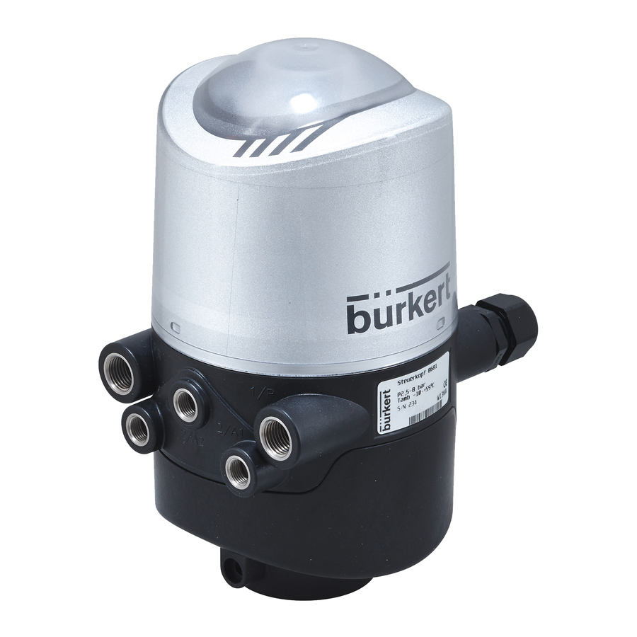
Burkert 8681 Quick Start Manual
Control head for decentralized automation of hygienic process valves
Hide thumbs
Also See for 8681:
- Operating instructions manual (166 pages) ,
- Quick start manual (92 pages) ,
- Conversion instructions (31 pages)
Table of Contents
Advertisement
Available languages
Available languages
Quick Links
Download this manual
See also:
Quick Start Manual
Advertisement
Chapters
Table of Contents

Related Manuals for Burkert 8681


Summary of Contents for Burkert 8681
- Page 1 Type 8681 Control Head Steuerkopf Tête de commande Quickstart English Deutsch Français...
- Page 2 We reserve the right to make technical changes without notice. Technische Änderungen vorbehalten. Sous réserve de modifications techniques. © Bürkert Werke GmbH, 2010 - 2014 Operating Instructions 1412/04_EU-ML_00810362 / Original DE...
-
Page 3: Table Of Contents
Type 8681 TabelofContents 7.2. Assembly ..................11 1. THE QUICKSTART ..................5 7.3. Pneumatic Installation ..............11 1.1. Definition of term “Device“ ............5 7.4. Opening and Closing the Housing ..........12 1.2. Symbols ....................5 7.5. Electrical Installation ..............12 2. AUTHORIZED USE ..................6 8. 24 V DC - DESIGN ..................13 2.1. - Page 4 Type 8681 11. 120 V AC - DESIGN .................. 22 11.1. Connection ..................22 11.2. Electrical Data ................22 11.3. Electrical Installation ..............23 12. POSITION MEASURING SYSTEM ............. 24 12.1. Teach-In ..................24 12.2. Teach-Reset ..................25 12.3. Autotune ..................25 12.4. LED - Color Assignments ............25 13. START-UP ...................... 25 14. PACKAGING, TRANSPORT, STORAGE, DISPOSAL ....
-
Page 5: The Quickstart
Quickstart explains, for example, how to install and start-up the device. CAUTION! A detailed description of the device can be found in the operating instructions for the Type 8681. Warns of a possible danger! • Failure to observe this warning may result in a moderate or minor injury. -
Page 6: Authorized Use
Before loosening pneumatic lines and valves, turn off the pressure Bürkert Service Center. and vent the lines. • The device may be used only in conjunction with third-party devices and components recommended and authorized by Burkert. Danger of explosion in explosive atmosphere (only in the event of a fault as it is zone 2)! • Any unauthorized reconstructions and changes to the control head are prohibited for safety reasons. - Page 7 • the general rules of technology apply to application planning and Control Head Type 8681 was developed with due conside- operation of the device. ration given to accepted safety rules and is state-of-the-art.
-
Page 8: General Information
Warranty nection 2/A1), as well as The warranty is only valid if the Control Head Type 8681 is used as • a mechanical manual control accessible when the hood is open on intended in accordance with the specified application conditions. -
Page 9: Structure
TechnicalData 5.2. Structure TECHNICAL DATA Position measuring system with LED’s 6.1. Conformity In accordance with the EC Declaration of conformity, the type 8681 Electronics module Flow restriction is compliant with the EC Directives. screw(s) of (with service interface, solenoid valves connection terminals, 6.2. -
Page 10: Mechanical Data
Type 8681 TechnicalData 6.4. Mechanical Data Air rate of solenoid valve: 110 I /min (for de-/aeration, ventilation) Dimensions: see data sheet (110 I /min - supplied state Housing material: outside: PA, PC, PPO, VA 200 I /min - maximum typical flow-rate) inside: ABS, PA, PMMA... -
Page 11: Assembly / Installation
Assembly/Installation ASSEMBLY / INSTALLATION 7.2. Assembly For the installation of the Control Head Type 8681 to a process 7.1. Safety instructions valve, you will require a process valve-specific hub flange as an adapter. The hub flange must be adapted to the design of the DANGER! process valve. -
Page 12: Opening And Closing The Housing
Type 8681 Assembly/Installation 7.4. Opening and Closing the Housing Sealing Opening: lugs at the → housing Loosen seal, if housing has been secured. → Open the plastic hood by turning counterclockwise (all the way, approx. 1.5 cm). Exhaust air Supply connection pressure Closing: (Silencer) connection →... -
Page 13: Dc - Design
Type 8681 24VDC-Design 24 V DC - DESIGN Central display of the switching states: 42 mA with a power supply of 8.1. Connection options 24 V DC per illuminated display; Outputs/binary feedback signals: S1 out - S4 out Design: Normally open contact, PNP output short-circuit-proof, with self-clocking short-circuit protection Switchable output current: max. -
Page 14: Electrical Installation (24 V Dc)
Type 8681 24VDC-Design 8.3. Electrical Installation (24 V DC) Teach-In- Service buttons T1-3 interface DANGER! Danger of explosion in explosive atmosphere DIP switches Solenoid valve (only in the event of a fault as it is zone 2)! for color connection with coding the • Opening the hood or the housing in an explosive atmosphere is status LED for LED‘s... - Page 15 Type 8681 24VDC-Design An external initiator can be connected using the small 3-pin terminal Terminal strip 2 Configuration strip 2 (see “Fig. 4” or manual, chapter „Connection of an external 24 V Power supply 24 V for external initiator initiator“). S4 IN Input external initiator...
-
Page 16: As-I - Design
Type 8681 AS-i-Design AS-I - DESIGN 9.4. Electrical Data 9.1. Connection options Power supply for the solenoid valves: Standard: via AS-i Option: externally 29,5 ... 31,6 V DC acc. specification; (19,2 V DC to 21,0 ... 31,6 V DC acc. specific. Power24 31,6 V DC) left connection: Setting the solenoid valve’s power supply using jumpers on the 1 x M16 x 1,5 cable gland with Multi-pole connection (M12 plug AS-interface electronics module. -
Page 17: Electrical Installation As Interface
Type 8681 AS-i-Design Central display of the switching states: Risk of injury from improper installation! Power consumption: max. 33 mA or 1 W per illuminated • Installation may be carried out by authorized technicians only and display (at 30.5 V AS-i voltage) with the appropriate tools! Power supply via AS interface bus: Internal cabling work is not required for any of the AS Interface designs Power consumption from max. -
Page 18: Devicenet- Design
Type 8681 DeviceNet-Design 10. DEVICENET- DESIGN Inputs 3 discrete feedback signals of the position measuring system (pos. S1 - S3), 10.1. Connection 1 discrete feedback signal of the external initiators (S4), 1 analog position signal in mm, Supply via DeviceNet string (11 to 25 V DC), Switch level high signal ≥... -
Page 19: Electrical Data
Type 8681 DeviceNet-Design 10.4. Electrical Data Output reduction integrated via DeviceNet interface electronics Electrical power supply: 11 to 25 V DC (according to pull-in current 120 mA typ. / 200 ms (3 valves) specification) Holding current 100 mA typ. at 24 V DC (3 valves) Max. power consumption: 200 mA at 24 V DC... -
Page 20: Network Topology
Type 8681 DeviceNet-Design 10.6. Network Topology No internal cabling work is required for any of the DeviceNet designs. However, you will require the correspondingly assembled cable sets When installing a DeviceNet system, ensure that the terminating circuit with the pin assignments described below: of the data lines is correct. -
Page 21: Configuration Of The Safety Position Of Solenoid Valves If Bus Error
Type 8681 DeviceNet-Design 10.9. Configuration of the Safety Input-Assemblies Address Format of the Data attribute Position of Solenoid Valves if Bus value 0: OFF / value 1: ON Error S1…S4 4, 1, 3 Byte 0: Bit 0: position S1 If the bus fails, the solenoid valve is switched to a programmable Bit 1: position S2 safety position (factory setting: the solenoid valve is in the power-off-... -
Page 22: Ac - Design
Type 8681 120VAC-Design 11. 120 V AC - DESIGN Outputs/binary feedback signals: S1out - S3out 11.1. Connection Design: NO contact, L switching, short-circuit protection via auto- left connection: matically resetting fuse 1 x M16 x 1,5 switchable output cable gland for power supply and signals current: max. -
Page 23: Electrical Installation
Type 8681 120VAC-Design 11.3. Electrical Installation connection Teach-In- buttons for valve 1 WARNING! with status T1, T2, T3 connections for Danger of explosion in explosive atmosphere (zone 2)! valve 2, 3 with • See the note DANGER at chapter “8.3”, page 14! service status LED interface Risk of injury due to electrical shock (120 V AC)! DIP-switches •... -
Page 24: Position Measuring System
Type 8681 PositionMeasuringSystem 12. POSITION MEASURING SYSTEM Terminal strip 2 Configuration (external initiator) The recordable stroke range is between 0 and 80 mm. Power supply - live conductor Three Teach-In buttons have been provided for comparison with the S4 IN Input external initiator actual stroke range. -
Page 25: Teach-Reset
Autotune functions and Autotune sequences - see operating • Only adequately trained personnel should take the instructions. plant / the device in operation. 12.4. LED - Color Assignments → Assembly of the control head type 8681. S1 - green, continuously lit, → S2 - yellow, continuously lit, Pneumatic and electrical installation. -
Page 26: Packaging, Transport, Storage, Disposal
Type 8681 Packaging, T ransport, S torage, D isposal 14. PACKAGING, TRANSPORT, STORAGE, DISPOSAL NOTE! Transport / storage damage! Inadequately protected equipment may be damaged during transport or storage. • Protect the device during transportation / storage against moisture and dirt in shock-resistant packaging. • Avoid the effects of heat and cold which could result in tempera- tures above or below the permitted storage temperature. - Page 27 Typ 8681 Inhaltsverzeichnis 7.2. Montage ...................36 1. DER QUICKSTART ..................29 7.3. Pneumatische Installation .............36 1.1. Begriffsdefinition „Gerät“ .............29 7.4. Öffnen/Schließen des Gehäuses ..........37 1.2. Darstellungsmittel ................29 7.5. Elektrische Installation ..............37 2. BESTIMMUNGSGEMÄSSE VERWENDUNG ........30 8. 24 V DC - AUSFÜHRUNG ................ 37 2.1.
- Page 28 Typ 8681 11. 120 V AC - AUSFÜHRUNG ..............46 11.1. Anschlussmöglichkeit ..............46 11.2. Elektrische Daten .................46 11.3. Elektrische Installation ..............47 12. WEGMESSSYSTEM .................. 49 12.1. Teach-In ..................49 12.2. Teach-Reset ..................49 12.3. Autotune ..................49 12.4. LED - Farbzuordnungen .............49 13. INBETRIEBNAHME ................... 50 14. VERPACKUNG, TRANSPORT, LAGERUNG, ENTSORGUNG .................... 50...
-
Page 29: Der Quickstart
Der Quickstart erläutert beispielhaft die Montage und Inbetriebnahme Folge sein. des Gerätes. VORSICHT! Die ausführliche Beschreibung des Gerätes finden Sie in der Bedie- nungsanleitung für den Typ 8681 Warnt vor einer möglichen Gefährdung! • Nichtbeachtung kann mittelschwere oder leichte Verletzungen Die Bedienungsanleitung finden Sie im Internet unter: zur Folge haben. -
Page 30: Bestimmungsgemässe Verwendung
Typ 8681 BestimmungsgemäßeVerwendung BESTIMMUNGSGEMÄSSE 2.1. Beschränkungen VERWENDUNG Beachten Sie bei der Ausfuhr des Systems/Gerätes gegebenenfalls bestehende Beschränkungen. Bei nicht bestimmungsgemäßem Einsatz des Steuerkopfes Typ 8681 können Gefahren für Personen, Anlagen in der Umgebung und die Umwelt entstehen. • Der Steuerkopf ist konzipiert für den Einsatz als Ansteuerung pneumatisch betätigter Prozessventile und / oder für die Erfassung von deren Schaltzuständen. -
Page 31: Grundlegende Sicherheitshinweise
Typ 8681 GrundlegendeSicherheitshinweise GRUNDLEGENDE WARNUNG! SICHERHEITSHINWEISE Gefahr durch elektrische Spannung! Diese Sicherheitshinweise berücksichtigen keine • Vor Eingriffen in das Gerät oder die Anlage, Spannung abschal- • Zufälligkeiten und Ereignisse, die bei Montage, Betrieb und Wartung ten und vor Wiedereinschalten sichern! der Geräte auftreten können. -
Page 32: Allgemeine Hinweise
Gehäuseteile und Schrauben nicht lackieren. Voraussetzung für die Gewährleistung ist der bestimmungsgemäße • Den sicher geschlossenen Steuerkopf nur mit materialverträglichen Gebrauch des Steuerkopfes Typ 8681 unter Beachtung der spezifi- Reinigungsmitteln reinigen und gründlich mit klarem Wasser zierten Einsatzbedingungen. -
Page 33: Aufbau Und Funktion
Typ 8681 AufbauundFunktion AUFBAU UND FUNKTION 5.2. Aufbau Der Steuerkopf Typ 8681 ist konzipiert für den Einsatz als Ansteuerung Wegmesssystem mit LED‘s pneumatisch betätigter Prozessventile und / oder für die Erfassung von deren Schaltzuständen. Elektronikmodul Drosselschrauben Zur Erfassung der Prozessventilschaltstellungen und deren Rück-... -
Page 34: Technische Daten
6.4. Mechanische Daten Maße: siehe Datenblatt 6.1. Konformität Gehäusematerial: außen: PA, PC, PPO, VA Der Steuerkopf Typ 8681 ist konform zu den EG-Richtlinien entspre- innen: ABS, PA, PMMA chend der EG-Konformitätserklärung. Dichtungsmaterial: außen: CR, EPDM 6.2. Normen innen: EPDM, FKM, NBR Die angewandten Normen, mit denen die Konformität mit den EG-Richt-... -
Page 35: Daten Wegmesssystem
Typ 8681 Montage/Installation Anschlüsse: MONTAGE / INSTALLATION Zu- und Abluftanschluss G1/4 Arbeitsanschlüsse G1/8 7.1. Sicherheitshinweise 6.6. Daten Wegmesssystem GEFAHR! Hubbereich: 0 ... 80 mm Verletzungsgefahr durch hohen Druck in der Anlage! ≤ 0,1 mm Auflösung: • Vor dem Lösen von Leitungen oder Ventilen den Druck abschalten Gesamtfehler: ± 0,5 mm (bei Verwendung eines und Leitungen entlüften. -
Page 36: Montage
Typ 8681 Montage/Installation 7.2. Montage Verplombungs- Zur Montage des Steuerkopfes Typ 8681 an ein Prozessventil nasen benötigen Sie einen prozessventilspezifischen Aufnahmeflansch als am Gehäuse Adapter. Der Aufnahmeflansch muss der Bauform des Prozessventiles angepasst sein. → Die Kolbenstange mit Target auf die Prozessventilspindel montieren. -
Page 37: Öffnen/Schließen Des Gehäuses
Typ 8681 24VDC-Ausführung 7.4. Öffnen/Schließen des Gehäuses 24 V DC - AUSFÜHRUNG Öffnen: 8.1. Anschlussmöglichkeiten → Verplombung lösen, falls Gehäuse gesichert. → Kunststoffhaube durch Drehen gegen den Uhrzeigersinn (bis Anschlag, ca. 1,5 cm) öffnen. Schließen: → Kunststoffhaube so auf das Unterteil aufsetzen, dass die inneren „Nasen“ über den Befestigungsnuten liegen und die äußeren Verplombungsnasen fast übereinander liegen. -
Page 38: Elektrische Installation (24 V Dc)
Typ 8681 24VDC-Ausführung Magnetventile: 8.3. Elektrische Installation (24 V DC) Max. Schaltleistung max. 0,9 W (je Magnetventil) GEFAHR! Typ. Dauerleistung 0,6 W (je Magnetventil) Betriebsart: Dauerbetrieb (100 % ED) Explosionsgefahr in Ex-Atmosphäre (Ex-Atmosphäre nur im Störfall, da Zone 2)! Zentrale Anzeige der Schaltzustände: 42 mA bei Spannungsversorgung 24 V DC • Öffnen der Haube bzw. des Gehäuses unter Ex-Atmosphäre ist je dargestellter Leuchtanzeige nur im spannungslosen Zustand zulässig! - Page 39 Typ 8681 24VDC-Ausführung Klemmleiste 2 Belegung Teach-In- Service- Tasten T1-3 Schnittstelle 24 V Spannungsversorg. 24 V DC für externen Initiator S4 IN Eingang externer Initiator DIP-Schalter zur Anschluss Farbcodierung GND externer Initiator mit Status-LED der LED‘s für Magnetventil → Gehäuse schließen →...
-
Page 40: As-I - Ausführung
Typ 8681 AS-I-Ausführung Ein externer Initiator kann über die 3-fach-Klemmleiste 2 ange- AS-I - AUSFÜHRUNG schlossen werden (siehe „Bild 4“ bzw. siehe Bedienungsanleitung, 9.1. Anschlussmöglichkeiten Kapitel „Anschluss eines Externen Initiators“). Ein- und Ausgangssignale zur übergeordneten Steuerung (SPS): Pin 3 - S1 out... -
Page 41: Elektrische Daten
Typ 8681 AS-I-Ausführung 9.4. Elektrische Daten Zentrale Anzeige der Schaltzustände: Stromaufnahme max. 33 mA bzw. 1 W je dargestellter Spannungsversorgung der Magnetventile (MV): Leuchtanzeige (bei 30,5 V AS-i- Spannung) Einstellung der Spannungsversorgung der Magnetventile über Jumper auf dem AS-Interface-Elektronikmodul. Spannungsversorgung über AS-Interface - Bus: Standard: über AS-i Option: extern max. Stromaufnahme 29,5 ... 31,6 V DC gemäß Spezifikation;... -
Page 42: Devicenet - Ausführung
Typ 8681 DeviceNet-Ausführung 10. DEVICENET - AUSFÜHRUNG Verletzungsgefahr bei unsachgemäßer Installation! • Die Installation darf nur autorisiertes Fachpersonal mit geeignetem 10.1. Anschlussmöglichkeit Werkzeug durchführen! Bei Varianten mit Multipolanschluss sind keine internen Verkabelungs- arbeiten notwendig. Sie benötigen allerdings entsprechend konfek- tionierte bzw. montierte Kabelsätze mit folgenden Pin-Belegungen. -
Page 43: Länge Der Busleitung
Typ 8681 DeviceNet-Ausführung Eingänge 3 diskrete Rückmeldesignale des Wegmess- Die maximale Stichleitungslänge (Drop Line) beträgt für: systems (Positionen S1 - S3) Baudrate Stichleitung Summe (im Netzwerk) 1 diskretes Rückmeldesignal des externen 156 m Initiators (S4) 78 m 1 analoges Wegsignal in mm Versorgung über DeviceNet-Strang... -
Page 44: Elektrische Installation (Dvn)
Typ 8681 DeviceNet-Ausführung Eingänge (aus Mastersicht) / binäre bzw. analoge Rückmel- WARNUNG! designale: Die Gewinnung der 3 binär zurückgemeldeten Ventilpositionen bzw. Verletzungsgefahr durch Stromschlag! des analogen Wegsignals ist in der Bedienungsanleitung im Kapitel • Vor Eingriffen ins System (außer Teach-In-Vorgang in Nicht-Ex- „Wegmesssystem“ beschrieben. Atmosphäre) die Spannung abschalten, vor Wiedereinschalten sichern! Die geltenden Unfallverhütungs- und Sicherheitsbestim-... -
Page 45: Netztopologie
Typ 8681 DeviceNet-Ausführung Weitere Einstellungen - siehe Bedienungsanleitung, Kap. „Konfigu- Ein externer Initiator kann über die rieren der DeviceNet-Adresse / Baudrate“. 3-fach-Klemmleiste angeschlossen werden - siehe Bedienungsanleitung, 10.8. Konfiguration der Prozessdaten Kap. „Anschluss eines Externen Initiators“. Zur Übertragung von Prozessdaten über eine I/O-Verbin dung stehen 2 statische Input- und 1 statisches Output-Assembly zur Auswahl - Details siehe Bedienungsanleitung, Kapitel „Konfiguration der Prozessdaten“. -
Page 46: Sicherheitsstellung Der Magnetventile Bei Busfehler
Typ 8681 120VAC-Ausführung 11. 120 V AC - AUSFÜHRUNG Output-Assembly Adresse Format des Datenattributs Wert 0: OFF / Wert 1: ON 11.1. Anschlussmöglichkeit Magnetventil 1 ... 3 4, 21, 3 Byte 0: Bit 0: MV1 linker Anschluss: Bit 1: MV2 1 x M16 x 1,5 Kabelverschraubung Bit 2: MV3 für Spannungsversorgung und Signale Bit 3…7: nicht benutzt... -
Page 47: Elektrische Installation
Typ 8681 120VAC-Ausführung Ausgänge/binäre 11.3. Elektrische Installation Rückmeldesignale: S1out - S3out WARNUNG! Bauart: Schließer (NO), L-schaltend, Kurzschlussschutz durch Explosionsgefahr in Ex-Atmosphäre (Zone 2) selbstrückstellende Sicherung • siehe GEFAHR-Hinweis in Kapitel „8.3“ auf Seite 38! schaltbarer Ausgangsstrom: max. 50 mA je Rückmeldesignal Verletzungsgefahr durch Stromschlag (120 V AC)! Ausgangsspannung • Beim Einstellen des Wegmesssystems (Teach-in) keine span- ≥... - Page 48 Typ 8681 120VAC-Ausführung Klemmleiste 2 Belegung (externer Initiator) Teach-In- Anschluss Tasten T2, mit Status- Spannungsversorgung - Leiter LED für T3, T1 S4 IN Eingang externer Initiator Anschlüsse mit Spannungsversorgung - Nullleiter Status-LED für Service- MV2, 3 → Gehäuse schließen. Schnittstelle → Sicherstellung des IP-Schutzes (Blindstopfen)
-
Page 49: Wegmesssystem
Typ 8681 Wegmesssystem → 12. WEGMESSSYSTEM Steuerkopf und Anlage gegebenenfalls zurück in den Normalzu- stand bringen (Schaltstellung, Spannungsversorgung). Der erfassbare Hubbereich beträgt 0 ... 80 mm. → Gehäuse schließen. Für den Abgleich auf den realen Hubbereich sind 3 Teach-In-Tasten vorgesehen. -
Page 50: Inbetriebnahme
• Nur ausreichend geschultes Personal darf die Anlage/das Gerät • Lagertemperatur: -20 … +65 °C. in Betrieb nehmen. HINWEIS! → Montage des Steuerkopfs 8681. Umweltschäden durch von Medien kontaminierte Geräteteile. → Pneumatische und elektrische Installation. • Geltende Entsorgungsvorschriften und Umweltbestimmungen → Einstellen des Wegmesssystems (Teach-In). - Page 51 Type 8681 Sommaire 7.3. Installation pneumatique ...............59 1. QUICKSTART ....................53 7.4. Ouverture et fermeture du boîtier ..........60 1.1. Définition du terme « appareil » ..........53 7.5. Electrical Installation ..............60 1.2. Symbols ....................53 8. VERSION 24 V DC ..................61 2. UTILISATION CONFORME...............
- Page 52 Type 8681 11. VERSION 120 V AC ................... 71 11.1. Possibilité de raccordement ............71 11.2. Caractéristiques électriques .............71 11.3. Installation électrique (120 V) ...........72 12. SYSTÈME DE MESURE DE DÉPLACEMENT ....... 73 12.1. Teach-In ..................73 12.2. Teach-Reset ..................74 12.3. Autotune ..................74 12.4. Affectation des couleurs des LED ...........74 13. MISE EN SERVICE ..................
-
Page 53: Quickstart
Quickstart explique, par des exemples, le montage et la mise en service de l‘appareil. ATTENTION ! Vous trouverez la description détaillée dans le instructions de service du type 8681 «Tête de commande» Met en garde contre un risque possible ! • Le non-respect peut entraîner des blessures légères ou de moyenne gravité. -
Page 54: Utilisation Conforme
Type 8681 Utilisationconforme UTILISATION CONFORME CONSIGNES DE SÉCURITÉ FONDAMENTALES L’utilisation non conforme de la tête de commande type 8681 peut présenter des dangers pour les personnes, les installa- Ces consignes de sécurité ne tiennent pas compte tions proches et l’environnement. • des hasards et des événements pouvant survenir lors du montage, • La tête de commande est conçue pour être utilisée comme de l’exploitation et de la maintenance des appareils. - Page 55 La tête de commande type 8681 a été développée dans le respect des règles reconnues en matière de sécurité et correspond à l’état actuel de la technique. Néanmoins, des risques peuvent se présenter.
-
Page 56: Indications Générales
Type 8681 Indicationsgénérales INDICATIONS GÉNÉRALES DESCRIPTION DU SYSTÈME La tête de commande type 8681 est conçue pour être utilisée comme 4.1. Les adresses : commande des vannes de process pneumatiques et/ou pour la Allemagne : détection de leurs états de commutation. Bürkert Fluid Control Systems La tête de commande est dotée d’un système de mesure de Sales Center déplacement sans contact fonctionnant avec trois signaux de retour... -
Page 57: Structure
CARACTÉRISTIQUES TECHNIQUES Système de mesure de déplacement 6.1. Conformité avec LED tricolores ILe type 8681 est conforme aux directives CE sur la base de la décla- Vis-pointeau(x) Module électronique ration de conformité CE. pour P et R (avec interface de service, bornes de raccordement, (2 par électrovanne) -
Page 58: Caractéristiques Mécaniques
Type 8681 Caractéristiquestechniques 6.4. Caractéristiques mécaniques Débit d’air de l’électrovanne : 110 I /mn (pour alimentation et échappement, Dimensions: voir la fiche technique soulèvement) Matériau du boîtier : extérieur : PA, PC, PPO, VA, (110 I - à la livraison intérieur : ABS, PA, PMMA 200 I - débit type maximal) -
Page 59: Montage/Installation
Montage/Installation MONTAGE/INSTALLATION 7.2. Montage Le montage de la tête de commande type 8681 sur une vanne de 7.1. Consignes de sécurité process nécessite une bride support spécifique à la vanne de process en tant qu’adaptateur. La bride support doit être adaptée à la construction DANGER! de la vanne de process. -
Page 60: Ouverture Et Fermeture Du Boîtier
Type 8681 Montage/Installation 7.4. Ouverture et fermeture du boîtier Bec de Ouverture : plombage → Retirer le plombage, si le boîtier est fixé. → Ouvrir le capot en plastique en tournant dans le sens contraire des aiguilles d’une montre (jusqu’en butée, env. 1,5 cm). Raccord... -
Page 61: Version 24 V Dc
Type 8681 Version24VDC VERSION 24 V DC Électrovannes : Puissance de coupure maxi : 0,9 W (par électrovanne) 8.1. Possibilités de raccordement Puissance continue typ. : 0,6 W (par électrovanne) Mode de fonc- tionnement : Fonctionnement continu (100 %) Affichage centralisé des états de commutation : 42 mA pour une alimentation en tension de 24 V DC par voyant lumineux représenté... -
Page 62: Installation Électrique (24Vdc)
Type 8681 Version24VDC Entrées commande de vannes (Y1 - Y3) : Raccordement : Passe-câbles → Niveau de Ouvrir le boîtier. signal - activé : U > 10 V, 24 V DC maxi + 10 % → Confectionner les câbles de raccordement pour les signaux et l’alimentation en tension ainsi que, éventuellement, pour le fin de course externe conformément aux règles de la technique. - Page 63 Type 8681 Version24VDC Borne plate 1 Affectation Broche Désignation Affectation 24 V Alimentation en tension 24 V 24 V Alimentation en tension 24 V S1 OUT Sortie position 1 S1 OUT Sortie position S1 S2 OUT Sortie position 2 S2 OUT Sortie position S2...
-
Page 64: Version As-I
Type 8681 VersionAS-i VERSION AS-I Signaux d’entrée et de sortie vers la commande principale (API) : Broche 3 - S1 out Broche 2 - GND 9.1. Possibilités de raccordement Broche 4 - S2 out Broche 1 - 24 V Broche 5 - S3 out... -
Page 65: Caractéristiques Électriques
Type 8681 VersionAS-i Sorties (du point de vue maître) / électrovannes : câble rond menant directement à la tête de commande (voir l’exemple de calcul en l’instructions de service). Puissance de coupure maxi : 0,9 W (par électrovanne) Puissance continue typ. : 0,6 W (par électrovanne) 9.4. Caractéristiques électriques Courant de démarrage :... -
Page 66: Installation Électrique (As-I)
Type 8681 VersionAS-i 9.5. Installation électrique (AS-i) De même, le cavalier peut être réglé sur le module électronique AS-i conforme l‘alimentation en tension des électrovannes (EV) (via l‘AS-i AVERTISSEMENT ! ou externe) - voir figure à la page 65 . Risque d’explosion en atmosphère explosible (zone 2) ! alimentation en tension des EV •... -
Page 67: Version Devicenet
Type 8681 VersionDeviceNet 10. VERSION DEVICENET Alimentation par le faisceau DeviceNet (11 ... 25 V DC) Niveau de commutation signal High ≥ 5 V 10.1. Possibilité de raccordement Niveau de commutation signal Low ≤ 1,5 V Raccord gauche : Sorties 3 électrovannes 1 x M16 x 1,5 passe-câbles avec Puissance absorbée... -
Page 68: Caractéristiques Électriques
Type 8681 VersionDeviceNet 10.4. Caractéristiques électriques Courant de démarrage : 120 mA typ. / 200 ms (3 vannes) Alimentation en tension : 11 ... 25 V DC (selon spécifica- Courant d’arrêt : 100 mA typ. à 24 V DC (3 vannes) tion) Mode de fonc- Courant absorbé maxi :... -
Page 69: Topologie Réseau
Type 8681 VersionDeviceNet Les variantes avec raccord multipolaire ne nécessitent pas de travaux 10.6. Topologie réseau de câblage internes. Vous avez cependant besoin des jeux de câbles Lors de l’installation d’un système DeviceNet, il convient de veiller à ce confectionnés resp. montés avec l’affectation des broches suivante : que le câblage de terminaison des lignes de transmission des données... -
Page 70: Position De Sécurité Des Électrovannes En Cas De Défaut Bus
Type 8681 VersionDeviceNet 10.9. Position de sécurité des «Adresse» dans le tableau c’est l’adresse attribut de données des ensembles pour l’accès en lecture: Class, Instance, Attribute. électrovannes en cas de défaut Adresse Format de l’attribut de données En cas de panne du bus, l’électrovanne passe dans une position Valeur 0 : OFF / Valeur 1 : ON de sécurité programmable (par défaut : électrovanne sans courant) S1…S4... -
Page 71: Version 120 V Ac
Type 8681 Version120VAC 11. VERSION 120 V AC Sorties/signaux de retour binaires : S1out - S3out 11.1. Possibilité de raccordement Construction : contact de fermeture (NO), commutation à gauche, à protection Raccord gauche : contre les courts-circuits par fusible 1 x M16 x 1,5 passe-câbles à réarmement automatique (pour l‘alimentation en tension et les... -
Page 72: Installation Électrique (120 V)
Type 8681 Version120VAC → 11.3. Installation électrique (120 V) Fixer les fils aux bornes de raccordement conformément aux affecta- tions de raccordement décrites dans la figure (regardez à la « Fig. 8 »). AVERTISSEMENT ! Touches Raccorde- Risque d’explosion en atmosphère explosible (zone 2) ! ment d’él.- Teach-In vanne avec T2, T3, T1 •... -
Page 73: Système De Mesure De Déplacement
Type 8681 Systèmedemesurededéplacement 12. SYSTÈME DE MESURE DE Entrée électrovanne (EV) 1 DÉPLACEMENT Entrée électrovanne (EV) 2 La course détectable est de 0 ... 80 mm. Trois touches Teach-In Entrée électrovanne (EV) 3 permettent d’effectuer la compensation sur la course réelle. Borne plate 2 Affectation (fin de course externe) 12.1. Teach-In... -
Page 74: Teach-Reset
Les fonctions autotune et déroulement de autotune - voir les instruc- un personnel suffisamment formé. tions de service. → 12.4. Affectation des couleurs des LED Montage de la tête de commande type 8681. → S1 - vert, illumination permanent, Installation pneumatique et électrique. S2 - jaune, illumination permanent, →... -
Page 75: Emballage, Transport, Stockage, Elimination
Type 8681 Emballage, T ransport, S tockage, E limination 14. EMBALLAGE, TRANSPORT, STOCKAGE, ELIMINATION REMARQUE ! Dommages dus au transport et stockage! Les appareils insuffisamment protégés peuvent être endommagés pendant le transport ou stockage. • Transportez / stockez l’appareil à l’abri de l’humidité et des impu- retés et dans un emballage résistant aux chocs. - Page 76 www.burkert.com...
Need help?
Do you have a question about the 8681 and is the answer not in the manual?
Questions and answers