Burkert 8681 Operating Instructions Manual
Control head
Hide thumbs
Also See for 8681:
- Operating instructions manual (166 pages) ,
- Quick start manual (92 pages) ,
- Conversion instructions (31 pages)
Table of Contents
Advertisement
Quick Links
Advertisement
Table of Contents

Related Manuals for Burkert 8681


Summary of Contents for Burkert 8681
- Page 1 Type 8681 Control Head Operating Instructions...
- Page 2 We reserve the right to make technical changes without notice. Technische Änderungen vorbehalten. Sous resérve de modification techniques. © 2010 - 2011 Bürkert Werke GmbH Operating Instructions 1103/03_EN_00806150 / Original DE...
-
Page 3: Table Of Contents
Control Head Type 8681 Control Head Type 8681 nhalt Operating instructiOns ...............................8 authOrized use .....................................9 2.1. export restrictions ................................9 predictable Misuse ................................9 2.2. Basic safety instructiOns .............................10 general infOrMatiOn ................................12 4.1. contact address ..................................12 4.2. Warranty ....................................12 4.3. information on the internet ............................12 systeM descriptiOn ................................13... - Page 4 Control Head Type 8681 installatiOn ....................................23 7.1. safety instructions ................................23 7.2. assembly of the control head .............................23 7.2.1. hub flange ................................23 7.2.2. assembly sequence on the example of a double-seated Valve ..........24 7.2.3. realignment of the control head ......................25 7.2.4.
- Page 5 Control Head Type 8681 11.5. design aid ....................................42 11.6. safety instructions ................................43 11.7. electrical installation as interface ..........................44 11.8. programming data ................................46 deVicenet - design ..................................47 12.1. definition ....................................47 12.2. electrical connection option ............................47 12.3. devicenet specification ..............................47 12.3.1. total line length and maximum line length according to devicenet specification ..48 12.3.2.
- Page 6 Control Head Type 8681 13.3. design aid ....................................62 13.4. safety instructions ................................63 13.5. electrical installation / start-up ..........................63 cOnnectiOn Of an external initiatOr........................66 pOsitiOn Measuring systeM ............................67 15.1. setting the position Measuring system (teach-in) ..................67 15.2. teach-in functions ................................68 15.2.1. teach-in functions and teach-in reset ....................68 15.2.2.
- Page 7 Control Head Type 8681 spare parts ....................................87 shutdOWn ......................................88 21.1. safety instructions ................................88 21.2. dismantling the control head type 8681 ......................88 packaging and transpOrt ...............................89 stOrage ......................................89 dispOsal ......................................89 english...
-
Page 8: Operating Instructions
Control Head Type 8681 Operating Instructions OperaTing insTruCTiOns The operating instructions describe the entire life cycle of the device. Keep these instructions in a location which is easily accessible to every user, and make these instructions available to every new owner of the device. -
Page 9: Authorized Use
Control Head Type 8681 Authorized use auTHOrized use non-authorized use of the control head type 8681 may be a hazard to people, nearby equipment and the environment. • The Control Head has been designed for use as actuation of pneumatically operated process valves and / or for recording the switching states of these. -
Page 10: Basic Safety Instructions
Control Head Type 8681 Basic Safety Instructions BasiC safeTy insTruCTiOns These safety instructions do not make allowance for any • contingencies and events which may arise during the installation, operation and maintenance of the devices. • local safety regulations - the operator is responsible for observing these regulations, also with reference to the installation personnel. - Page 11 For further information refer to the corresponding chapters of these operating instructions! Control Head Type 8681 was developed with due consideration given to accepted safety rules and is state- of-the-art. Nevertheless, dangerous situations may occur. Failure to observe this operating manual and its operating instructions as well as unauthorized tampering...
-
Page 12: General Information
The warranty is only valid if the control head is used as intended in accordance with the specified application conditions. 4.3. information on the internet The operating instructions and data sheets for control head type 8681 can be found on the Internet at: www.buerkert.com english... -
Page 13: System Description
System Description sysTeM desCripTiOn 5.1. intended application area The Control Head Type 8681 has been designed for use as actuation of pneumatically operated process valves and / or for recording the switching states of these. 5.2. general description The Control Head Type 8681 is used for actuating pneumatically operated process valves. -
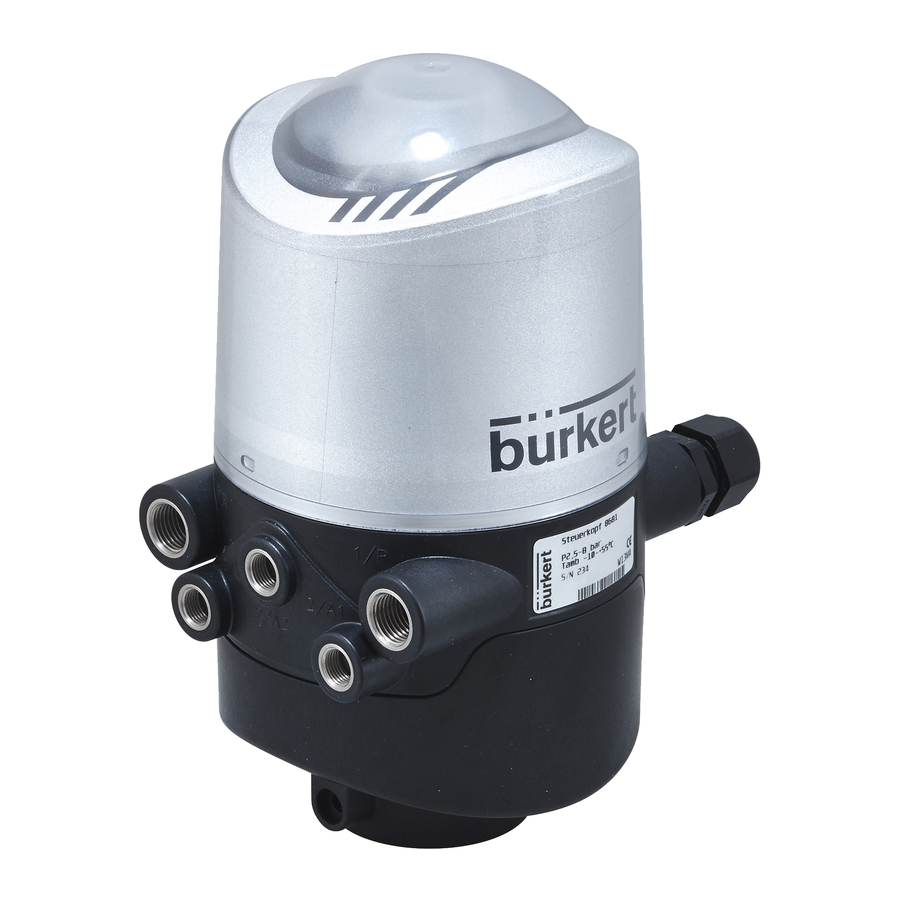
Page 14: Functions / Options / Designs
Exhaust air connection (3/R) Working connections screws M5); no sealing (2/A1 - 3) Silencer in the exhaust air function, merely as protection connection (3/R), not shown against pulling off from the hub flange Fig. 1: Structure of Control Head Type 8681 english... -
Page 15: Fluid Diagram
Control Head type 8681 - Fluid diagram (with restriction capability for each solenoid valve): Model with three Type 6524 solenoid valves, e.g. for double-seated valve Fig. 2: Fluid diagram (model: 3 solenoid valves) The functions and designs of Control Head Type 8681 are described in the following chapters. english... -
Page 16: Number Of Solenoid Valves
Control Head Type 8681 System Description 5.4.3. number of solenoid valves The control head for process valves has been designed for single-acting and double-acting valve actuators as well as for double-seated and multi-position valves. number of solenoid valves type of use... -
Page 17: Position Measuring System
Control Head Type 8681 System Description 5.4.6. position Measuring system The switching positions of the process valves are reported to the higher-level control by feedback signals from the contactless position measuring system. Connection to the control head is done by means of a simple adap- tation to the process valve's piston. -
Page 18: Technical Data
Control Head Type 8681 Technical Data TeCHniCal daTa 6.1. Operating Conditions Danger! danger of explosion in explosive atmosphere (only in the event of a fault as zone 2)! • Do not expose the device to any mechanical or thermal loads that will exceed the limits described in the oper- ating instructions. -
Page 19: Mechanical Data
Control Head Type 8681 Technical Data 6.3. Mechanical data M16x1.5 (2x) Cover safeguard: - Seal max Ø2 and / or - plastic self-cutting screw 3.0x10 G1/4 (2x) G1/8 (3x) Fig. 3: Dimensional drawing Weight: ca. 0.8 kg housing material: outside:... -
Page 20: Pneumatic Data
Control Head Type 8681 Technical Data 6.4. pneumatic data control medium: oil-free and dry air, neutral gases Quality classes in accordance with DIN ISO 8573-1 (5 µm filter recommended) Dust content Quality class 5: max. particle size 40 µm, max. particle density 10 mg/m Water content Quality class 3: max. -
Page 21: Position Measuring System Data
Control Head Type 8681 Technical Data 6.5. position Measuring system data Stroke range (measuring range): 0 ... 80 mm ≤ 0.1 mm Resolution: Total fault: ± 0.5 mm - when using a target in accordance with the dimensional drawing, Material 1.4021 and a piston rod (Ø 22 mm, Material - see (*)) (Fault refers to the reproducibility of a taught position) The illustration in Fig. -
Page 22: Factory Settings In The Firmware
Control Head Type 8681 Technical Data 6.6. factory settings in the firmware The control head is supplied with the following factory settings of the firmware: The service interface may only be used in non-explosive atmosphere. Feedback areas (position measuring system): (A feedback area is the area, within which a position (e.g. -
Page 23: Installation
For the installation of the Control Head Type 8681 to a process valve, you will require a process valve-specific hub flange as an adapter. -
Page 24: Assembly Sequence On The Example Of A Double-Seated Valve
Control Head Type 8681 Installation The hub flange and non ferromagnetic piston rod with the target that is used to record the position must comply with the specifications with regard to material and stability (see chapter 6.5. Position Measuring System Data. -
Page 25: Realignment Of The Control Head
Control Head Type 8681 Installation → Mount the control head on the hub flange (seamlessly 360° rotatable). → Secure control head with the two locking screws (shoulder screws M5) in the middle groove of the hub flange to prevent pulling off from the hub flange – tightening torque: max. 3.2 Nm (see Fig. 7: Dimensional diagram of the control head - process valve adaptation and 7.2.3. -
Page 26: Opening And Closing The Housing
Control Head Type 8681 Opening and Closing the Housing Opening and ClOsing THe HOusing 8.1. safety instructions Danger! risk of injury from high pressure in the equipment! • Before loosening pneumatic lines and valves, turn off the pressure and vent the lines. -
Page 27: Closing The Housing
Control Head Type 8681 Opening and Closing the Housing 8.2.2. Closing the Housing If necessary, clean the seal contour of the seal and of the hood, and lightly lubricate it using a recom- mended silicone grease (e.g. Paraliq GTE 703). -
Page 28: Pneumatic Installation
Control Head Type 8681 Pneumatic Installation pneuMaTiC insTallaTiOn 9.1. safety instructions Danger! risk of injury from high pressure in the equipment! • Before loosening pneumatic lines and valves, turn off the pressure and vent the lines. Warning! risk of injury from improper installation! •... -
Page 29: Flow Restriction Function Of The Solenoid Valves
Control Head Type 8681 Pneumatic Installation procedure: → If necessary, realign the control head (see chapter 7.2.3. Realignment of the Control Head) → A silencer has already been mounted on the Exhaust Air Connection (3/R) in the supplied state. As needed, the silencer can be replaced by an exhaust air hose (e.g. - Page 30 Control Head Type 8681 Pneumatic Installation Settings of the Flow-rate or the Control Speed with the Help of the Flow restriction Screws: → Open the housing observing the notes contained in chapter 8. Opening and Closing the Housing. → For proper setting, it is advisable to turn the two flow restriction screws initially into the minimum flow-rate position.
-
Page 31: 24 V Dc - Design
Control Head Type 8681 24 V DC - Design 24 V dC - design 10.1. electrical connection options The following connection concepts are available for the electrical connection of the control head: Cable gland Cable gland with multi-pole connection (M12 plug according to IEC 61076-2-101, 12-pole) - Page 32 Control Head Type 8681 24 V DC - Design solenoid valves: Power input per solenoid valve: max. 0.8 W (0.9 W during activation) Power consumption per solenoid valve: 67 mA at 12 V DC 34 mA at 24 V DC...
-
Page 33: Design Aid
Control Head Type 8681 24 V DC - Design 10.3. design aid power consumption of the electronics: 0.7 W 30 mA at 24 V power consumption of a valve during activation (200 ms): 0.9 W 38 mA at 24 V... -
Page 34: Safety Instructions
Control Head Type 8681 24 V DC - Design 10.4. safety instructions Danger! danger of explosion in explosive atmosphere (only in the event of a fault as zone 2)! • Opening the hood or the housing in an explosive atmosphere is only allowed in the isolated state! - Page 35 Control Head Type 8681 24 V DC - Design note! use of the control head in explosive atmosphere • Only use cables and cable glands that are allowed for the respective application area, and mount the cable gland according to the respective operating instructions! •...
- Page 36 Control Head Type 8681 24 V DC - Design Circuit diagram 24 V DC: *) Order variant "Analog": output - analog signal Fig. 12: Circuit diagram 24 V DC english...
-
Page 37: Multi-Pole Connection
Control Head Type 8681 24 V DC - Design 10.5.2. Multi-pole Connection Internal cabling work is not required for models with multi-pole connection, which makes installation and start-up on site considerably easier and quicker, reducing the risk of leaks. However, you will require the correspondingly... -
Page 38: As Interface - Design
Control Head Type 8681 AS Interface - Design as inTerfaCe - design 11.1. definition aS interface Connection AS interface (Actuator Sensor Interface) is a field bus system which is used primarily for networking binary sensors and actuators (slaves) with a higher-level control (master). -
Page 39: Electrical Connection Options For As Interface
Control Head Type 8681 AS Interface - Design 11.2. electrical Connection Options for as interface The following connection concepts are available for the electrical connection of the control head: • Cable gland with multi-pole connection on a cable (8 cm length) •... -
Page 40: Electrical Data
Setting the valve's power supply using jumpers on the AS interface electronics module: via AS interface Externally (Connection see chapter 11.7. Electrical installation AS Interface) Jumper Jumper The Control Head Type 8681 was developed according to the Complete Specification (V.3.0) and the Profile S-7.A.E and S-7.F.F of the AS International Association. english... -
Page 41: Control Head Type
Control Head Type 8681 AS Interface - Design connections: Multi-pole connection version 1 x M16 x 1.5 cable gland / A/F19 with multi-pole connection (M12 plug according to IEC 61076-2-101, 4-pole on a cable of 8 or 80 cm length for power supply and signal) 1 x M16 x 1.5 cable gland / A/F19... -
Page 42: Design Aid
Control Head Type 8681 AS Interface - Design NOTE! if all three solenoid valves are simultaneously controlled via the as interface, the electronics will activate the valves sequentially with a 200 ms time delay to protect the as interface from overloads. -
Page 43: Safety Instructions
Control Head Type 8681 AS Interface - Design Calculation examples: example 1: 3 valves are activated simultaneously, one position is reported (state for 200 ms): + 1 x P + 2 x P + 1 x P Slave Valve-On Valve 4.5 W... -
Page 44: Electrical Installation As Interface
Control Head Type 8681 AS Interface - Design 11.7. electrical installation as interface Internal cabling work is not required for any of the AS Interface designs with multi-pole connection, which makes installation and start-up on site considerably easier and quicker, reducing the risk of leaks. - Page 45 Control Head Type 8681 AS Interface - Design The cable with multi-pole connection version is especially suited for direct and flexible connection to the AS interface cable harness using the ribbon cable terminal (M12 branch circuit, VA branch circuit) that is optionally available.
-
Page 46: Programming Data
Control Head Type 8681 AS Interface - Design 11.8. programming data The control heads have been configured as AS interface version with an extended address range (A/B slaves) for 62 slaves or optionally as an AS interface version for 31 slaves. -
Page 47: Devicenet - Design
Control Head Type 8681 DeviceNet - Design deViCeneT - design 12.1. definition • The DeviceNet is a field bus system which is based on the CAN protocol (Controller Area Network). It enables actuators and sensors (slaves) to be networked with higher-level controllers (master). -
Page 48: Total Line Length And Maximum Line Length According To Devicenet Specification
Control Head Type 8681 DeviceNet - Design Inputs 3 discrete feedback signal of the position measuring system (positions S1 - S3) 1 discrete feedback signal of the external initiator (S4) 1 analog position signal in mm supply via DeviceNet string (11 to 25 V DC) Switch level high signal ≥... -
Page 49: Electrical Data
Control Head Type 8681 DeviceNet - Design 12.4. electrical data connections: "Multi-pole" 1 x M16 x 1.5 cable gland / SW22 with multi-pole connection (M12 plug according to IEC 61076-2-101, 5-pole on a cable of 80 cm length ) for DeviceNet bus and power supply 1 x M16 x 1.5 cable gland / SW19 for external initiator... -
Page 50: Design Aid
Control Head Type 8681 DeviceNet - Design 12.6. design aid power consumption of the electronics: 1.44 W 60 mA at 24 V power consumption of a valve during activation (200 ms): 1.0 W 42 mA at 24 V Valve-ON Valve-ON power consumption of a valve after reduction: 0.8 W... -
Page 51: Safety Instructions
Control Head Type 8681 DeviceNet - Design 12.7. safety instructions Danger! danger of explosion in explosive atmosphere (only in the event of a fault as zone 2)! • Opening the hood or the housing in an explosive atmosphere is only allowed in the isolated state! - Page 52 Control Head Type 8681 DeviceNet - Design Devicenet electronics module: Teach-In buttons Solenoid valve T1-3 connection with status LED for Valve 1 Service DIP switches interface for setting the address and baud rate DIP switches for Status LED color coding...
-
Page 53: Network Topology Of A Devicenet System
Control Head Type 8681 DeviceNet - Design 12.9. network Topology of a devicenet system When installing a DeviceNet system, ensure that the terminating circuit of the data lines is correct. The circuit pre- vents the occurrence of interference caused by signals reflected onto the data lines. -
Page 54: Settings Of The Devicenet Address
Control Head Type 8681 DeviceNet - Design 12.10.1. settings of the devicenet address MAC ID address = Medium Access Control Identifier Address = [DIP 1 ⋅ 2 + DIP 2 ⋅ 2 + DIP 3 ⋅ 2 + DIP 4 ⋅ 2 + DIP 5 ⋅... -
Page 55: Setting The Baud Rate
Control Head Type 8681 DeviceNet - Design 12.10.2. setting the baud rate Adjustment of the control head to the baud rate of the network. Baud rate dip 7 dip 8 125 kbaud 250 kbaud 500 kbaud not permitted: (on) (on) if the settings are changed by actuating the dip switches, this change will not take effect until the device is restarted. -
Page 56: Static Output Assembly
Control Head Type 8681 DeviceNet - Design The addresses listed in the table above ("Static input assemblies") can be used as a path data for the attribute Produced Connection Path of an I/O connection. Nevertheless, by using this address data, the attributes combined in the assemblies can also be accessed acycli- cally via Explicit Messages. -
Page 57: Configuration Example
Control Head Type 8681 DeviceNet - Design 12.12.2. Configuration example The example describes the principle procedure when configuring the device using the software RSNetWorx for DeviceNet (Rev. 4.21.00). installation of the eDS File The EDS file is installed with the aid of the EDS Installation Wizard Tool associated with RSNetWorx. -
Page 58: Display Of The Status Leds In The Event Of A Bus Error
Control Head Type 8681 DeviceNet - Design online Parameterization of the Device Devices can also be parameterized online. In doing so, you can also select whether only individual param- eters (single) or all parameters (all) of a group are read from the device (upload) or are loaded into the device (download). -
Page 59: State Of Bus Status Led "Network
Control Head Type 8681 DeviceNet - Design 12.13.2. state of bus status led "network" device state explanation troubleshooting No voltage / not • Device is not supplied with voltage • Connect other devices, if the device online is the only network subscriber, •... -
Page 60: Ac - Design
Control Head Type 8681 120 V AC - Design 120 V aC - design 13.1. electrical connection options Cable gland: Connection left: Voltage, signals Connection right: external initiator Fig. 24: Connection concept 120 V AC 13.2. electrical data central power supply:... -
Page 61: Control Head Type
Control Head Type 8681 120 V AC - Design feedback signal output: S4 out is directly connected to S4 in input / proximity switches (external initiator: s4 in): Power supply: voltage present at control head U = 120 V AC, 50/60 Hz... -
Page 62: Design Aid
Control Head Type 8681 120 V AC - Design 13.3. design aid power consumption of the electronics: 1.2 VA 10 mA at 120 VA power consumption of a valve during activation (200 ms): 1.7 VA 14 mA at 120 VA... -
Page 63: Safety Instructions
Control Head Type 8681 120 V AC - Design 13.4. safety instructions Danger! risk of injury due to electrical shock (110 ... 130 V ac)! • Before reaching into the system (except for the Teach-In procedure in a non-explosive atmosphere) switch off the power supply and secure it to prevent restarting! •... - Page 64 Control Head Type 8681 120 V AC - Design Danger! risk of electric shock if the pe connection is not connected! • the PE connection must be connected! → Clamp the protective conductor to the PE connection. → Check correct grounding.
- Page 65 Control Head Type 8681 120 V AC - Design designation designation configuration configuration for external initiator terminal strip terminal strip Protection earth - Electrical power supply - protective conductor live conductor S4 IN External initiator input Electrical live conductor power supply...
-
Page 66: Connection Of An External Initiator
Control Head Type 8681 Connection of an External Initiator COnneCTiOn Of an exTernal iniTiaTOr Danger! danger of explosion in explosive atmosphere (only in the event of a fault as zone 2)! • Opening the hood or the housing in an explosive atmosphere is only allowed in the isolated state! An external initiator can be connected using the small 3-pin screw terminal - according to the respective design - (see e.g. -
Page 67: Position Measuring System
Control Head Type 8681 Position Measuring System pOsiTiOn Measuring sysTeM The switching positions of the process valve are reported to the higher-level control by feedback signals from the contactless position measuring system. Connection to the control head is done by means of a simple adaptation to the process valve's piston. -
Page 68: Teach-In Functions
Control Head Type 8681 Position Measuring System → If necessary, return control head and system to normal state (switching position, power supply). → Close the housing observing the notes contained in chapter 8. Opening and Closing the Housing. If the piston or the target are located outside the measuring area during the teaching phase, the LED will flash 3 times in the defined fault color. -
Page 69: Autotune Functions
Control Head Type 8681 Position Measuring System 15.2.2. autotune functions teach-in Mode activa- opt. feed- teach-in Function activation opt. feed- button tion back button duration back duration Autotune 1 green + Autotune 2 green + yellow + Autotune 3 yellow +... - Page 70 Control Head Type 8681 Position Measuring System - Then position S2 is taught. - After that, valve V1 is deactivated. It initiates closing of the process valve. - Once the process valve is closed (after 15 s maximum), position S1 is displayed by LED.
- Page 71 Control Head Type 8681 Position Measuring System autotune 4: control effect on the process valve internal program error t2 + t3 autotune mode starts t1 + t2 Autotune 4 starts Valve closing Activate Wait period Closed position Teach Valve opens...
-
Page 72: Led - Color Assignments
Control Head Type 8681 LED - Color Assignments led - COlOr assignMenTs The switching states of the feedback positions are signaled centrally to the outside by super-bright LEDs so that quick visual control is possible also for large systems. The color assignments for all signals to the process valve states corresponds to the subsequently listed tables. -
Page 73: Setting The Color Combinations
Control Head Type 8681 LED - Color Assignments 16.1. setting the Color Combinations setting of the possible color combinations with the help of the dip switches: Fault DiP1 DiP2 DiP3 DiP4 green yellow green yellow green yellow green green yellow... -
Page 74: Signal Priorities
Control Head Type 8681 LED - Color Assignments Blinking patterns note permanent blinking in the fault color: - Teaching does not occur 250 ms 250 ms - Teach-Reset has been performed - Bus error permanent blinking in the color for that position:... -
Page 75: Service Mode / Manual Control
Control Head Type 8681 Service Mode / Manual Control serViCe MOde / Manual COnTrOl By default, the control head provides the following (e.g. for service purposes): • a magnetic manual control that is easily accessible from the outside for Solenoid Valve 1 (2/A1), as well as •... -
Page 76: Mechanical Manual Control
Control Head Type 8681 Service Mode / Manual Control procedure for activating & deactivating the manual control for valve location 2/a1: → Observe safety guidelines for the system prior to using the manual control. → Activating the magnetic manual control: Hold the manual control tool on the identification points between the cable glands for three seconds (see Fig. -
Page 77: Maintenance, Troubleshooting
Control Head Type 8681 Maintenance, Troubleshooting MainTenanCe, TrOuBlesHOOTing 18.1. safety instructions Danger! risk of injury from high pressure in the equipment! • Before loosening pneumatic lines and valves, turn off the pressure and vent the lines. danger of explosion in explosive atmosphere (only in the event of a fault as zone 2)! •... -
Page 78: Safety Positions
Control Head Type 8681 Maintenance, Troubleshooting 18.2. safety positions safety positions after failure of the electrical or pneumatic auxiliary power: safety positions after failure of the auxiliary power Operating mode process valve design electrical pneumatic single-acting Control function A down down •... -
Page 79: Maintenance
18.3. Maintenance When used properly, the Control Head Type 8681 operates maintenance and trouble-free. For service work, we offer spare part sets for certain components or modules (see chapter entitled "20. Spare Parts"). Repairs to the control head for use in explosive atmosphere, however, are only allowed by the manufacturer. - Page 80 Control Head Type 8681 Maintenance, Troubleshooting fault description possible cause of the fault troubleshooting Feedback signal is lost in Position in the limit range of the Repeat the Teach-In process system operation feedback area (see chapter 15.1. Setting the Position...
-
Page 81: Replacement Of Components And Modules
Control Head Type 8681 Replacement of Components and Modules replaCeMenT Of COMpOnenTs and MOdules If components or modules need to be replaced for maintenance or service reasons, please observe the following notes and descriptions. Devices that are used in the explosion-risk area may be repaired by the manufacturer only. -
Page 82: Changing The Electronics Module
Control Head Type 8681 Replacement of Components and Modules 19.2. Changing the electronics Module note! electrostatic sensitive components / modules! • The device contains electronic components, which react sensitively to electrostatic discharge (ESD). Contact with electrostatically charged persons or objects may be hazardous to these components. In the worst case scenario, they will be destroyed immediately or will fail after start-up. -
Page 83: Changing The Valves
Control Head Type 8681 Replacement of Components and Modules installation procedure: → Carefully insert the entire electronics module into the recess in the lower housing part. → Plug the electronics module carefully onto the contact pins for the position measuring system. -
Page 84: Changing The Position Measuring System
Control Head Type 8681 Replacement of Components and Modules → Loosen the electrical connections. → Loosen the connecting screws (Torx T10) for the corresponding valve module. → Take out the valve module and replace it with the spare part set. - Page 85 Control Head Type 8681 Replacement of Components and Modules Danger! risk of injury from high pressure! • Before loosening pneumatic lines and valves, turn off the pressure and vent the lines. note! electrostatic sensitive components / modules! • Before changing the position measuring system, switch the electrical power for the control head off so that destruction of the PCB and electronics module is avoided.
- Page 86 Control Head Type 8681 Replacement of Components and Modules → Loosen the electronics module's fastening screw (Torx 10) (see chapter 19.2. Changing the Electronics Module). → Tilt the electronics forwards to loosen the position measuring system's contact pins from the electronics module.
-
Page 87: Spare Parts
O-ring 100 x 1.78 EPDM 797946 8681-24V module, casted + programmed 196480 8681-AS interface module, casted + programmed 196481 8681-DeviceNet module casted + programmed 196482 8681-120V module casted + programmed 196483 Adapter compl. with Valve 6524 (incl. throttle module) -
Page 88: Shutdown
• Disassembly work may be carried out by authorized technicians only and with the appropriate tools! 21.2. dismantling the Control Head Type 8681 Prior to starting with the work, check the system status! procedure: Cable gland versions: →... -
Page 89: Packaging And Transport
Control Head Type 8681 Packaging and Transport paCkaging and TranspOrT NOTE! transport damage! Inadequately protected equipment may be damaged during transport. • During transportation protect the device against moisture and dirt in shock-resistant packaging. • Avoid the effects of heat and cold which could result in temperatures above or below the permitted storage temperature. - Page 90 www.burkert.com...
Need help?
Do you have a question about the 8681 and is the answer not in the manual?
Questions and answers