Burkert 8681 Operating Instructions Manual
Control head
Hide thumbs
Also See for 8681:
- Operating instructions manual (166 pages) ,
- Quick start manual (92 pages) ,
- Conversion instructions (31 pages)
Table of Contents
Advertisement
Advertisement
Table of Contents

Related Manuals for Burkert 8681


Summary of Contents for Burkert 8681
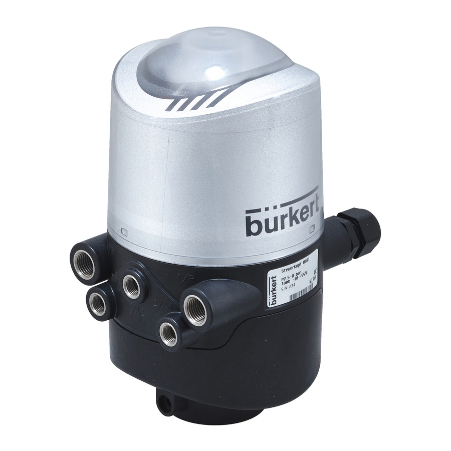
- Page 1 Type 8681 Control Head Operating Instructions...
- Page 2 We reserve the right to make technical changes without notice. Technische Änderungen vorbehalten. Sous resérve de modification techniques. © Bürkert Werke GmbH, 2010 - 2014 Operating Instructions 1412/05_EN_00806150 / Original DE...
-
Page 3: Table Of Contents
Control Head Type 8681 Control Head Type 8681 ontents OPERATING INSTRUCTIONS ................................8 AUTHORIZED USE .....................................9 2.1. Export restrictions .................................9 BASIC SAFETY INSTRUCTIONS ..............................10 GENERAL INFORMATION ................................12 4.1. Contact address ..................................12 4.2. Warranty ....................................12 4.3. Information on the Internet ............................12 SYSTEM DESCRIPTION ................................13 5.1. Intended application area ...............................13 5.2. General description ................................13 5.3. Functions / options / designs .............................14 5.3.1. Structure of the control head ........................14 5.3.2. Fluid diagrams ..............................15... - Page 4 Control Head Type 8681 6.7. Factory settings in the firmware ..........................25 6.7.1. Feedback fields (position measuring system) ..............25 6.7.2. Service / maintenance notification (maintenance request) ........26 6.7.3. Manual control function (magnetic) ...................26 6.8. Resetting the device (Device Reset) ........................27 ASSEMBLY ......................................28 7.1. Safety instructions ................................28 7.2. Assembly of the control head ............................28 7.2.1. Hub flange ................................28 7.2.2. Assembly sequence on the example of a double-seated valve ..........29 7.2.3. Realignment of the control head........................30 7.2.4. Assembly of the pneumatic and electrical connections ...............30 7.2.5. Recommended auxiliary materials ......................30 OPENING AND CLOSING THE HOUSING ..........................31 8.1. Safety instructions ................................31 8.2. Opening and closing the housing ..........................31 8.2.1. Opening the housing .
- Page 5 Control Head Type 8681 AS INTERFACE - DESIGN ................................43 11. 11.1. Definition ....................................43 11.2. Electrical connection options for AS interface ....................44 11.3. Number of connectable control heads and maximum length of the bus line ........44 11.4. Electrical data ..................................45 11.5. Design aid ....................................47 11.6. Safety instructions ................................48 11.7. Electrical installation of the AS interface .......................49 11.8. Programming data ................................51 DEVICENET - DESIGN ...................................52 12. 12.1. Definition ....................................52 12.2. Electrical connection option ............................52 12.3. DeviceNet specification ..............................52 12.3.1. Total line length and maximum line length according to DeviceNet specification ..53 12.3.2. Drop line length .
- Page 6 Control Head Type 8681 12.13. D isplay of the status LEDs in the event of a bus error ..................63 12.13.1. Status of the device status LED "Modules" ..................63 12.13.2. State of bus status LED "Network" ......................64 13. 120 V AC - DESIGN ..................................65 13.1. Electrical connection options ............................65 13.2. Electrical data ..................................65 13.3. Design aid ....................................66 13.4. Safety instructions ................................67 13.5. Electrical installation / start-up ...........................68 CONNECTION OF AN EXTERNAL INITIATOR ........................71 14. SPECIAL DESIGNS ..................................73 15.
- Page 7 Control Head Type 8681 18. SERVICE MODE / MANUAL CONTROL ..........................84 18.1. Magnetic manual control ..............................84 18.2. Mechanical manual control ............................85 MAINTENANCE, TROUBLESHOOTING ..........................86 19. 19.1. Safety instructions ................................86 19.2. Safety positions ...................................87 19.3. Maintenance / service ..............................88 19.4. Cleaning ....................................88 19.5. Malfunctions ..................................88 20. REPLACEMENT OF COMPONENTS AND MODULES ....................90 20.1. Safety instructions ................................90 20.2. Changing the electronics module ..........................91 20.3. Changing the valves ................................92 20.4. Changing the position measuring system ......................93...
-
Page 8: Operating Instructions
Control Head Type 8681 OperatingInstructions OPERATING INSTRUCTIONS The operating instructions describe the entire life cycle of the device. Keep these instructions in a location which is easily accessible to every user, and make these instructions available to every new owner of the device. -
Page 9: Authorized Use
Control Head Type 8681 AuthorizedUse AUTHORIZED USE Incorrect use of the control head Type 8681 may be dangerous to people, nearby equipment and the environment. • The control head has been designed for use as actuation of pneumatically operated process valves and / or for recording the switching states of these. • Use according to the authorized data, operating conditions and conditions of use specified in the contract documents and operating instructions. -
Page 10: Basic Safety Instructions
Control Head Type 8681 BasicSafetyInstructions BASIC SAFETY INSTRUCTIONS These safety instructions do not make allowance for any • contingencies and events which may arise during the assembly, operation, and maintenance of the devices. • local safety regulations – the operator is responsible for observing these regulations, also in relation to the instal- lation personnel. - Page 11 • Only use compatible cleaning agents for cleaning the securely closed control head and always rinse thoroughly with clean water. Control head Type 8681 was developed with due consideration given to accepted safety rules and is state- of-the-art. Nevertheless, dangerous situations may occur.
-
Page 12: General Information
The warranty is only valid if the control head is used as intended in accordance with the specified application conditions. 4.3. Information on the Internet The operating instructions and data sheets for control head type 8681 can be found on the Internet at: www.burkert.com > Documentation > Operating instructions/approvals > Type search English... -
Page 13: System Description
SystemDescription SYSTEM DESCRIPTION 5.1. Intended application area The control head Type 8681 has been designed for use as an actuator for pneumatically operated process valves and / or for recording the switching states of these. 5.2. General description The control head Type 8681 is used for actuating pneumatically operated process valves. -
Page 14: Functions / Options / Designs
2 locking screws (2/A1...3) (shoulder screws M5). Exhaust air connection (3/R) No sealing function, merely as protection Silencer in the exhaust air against pulling off from connection (3/R), not shown the hub flange Fig. 1: Structure of control head Type 8681 English... -
Page 15: Fluid Diagrams
Control Head Type 8681 SystemDescription 5.3.2. Fluid diagrams Control head Type 8681 - Fluid diagram (with restriction capability for each solenoid valve): Model with 3 solenoid valves Type 6524, e.g. for double-seated valve Fig. 2: Fluid diagram (model: 3 solenoid valves) -
Page 16: Number Of Solenoid Valves
Control Head Type 8681 SystemDescription Control head Type 8681 - design for double-acting actuators - fluid diagram (with restriction option of each solenoid valve): Model with 2 solenoid valves Type 6524 (solenoid valve 1: NC, solenoid valve 2: NO, for double-acting actuators (safety position) - see also Chapter “15. Special designs” on page 73. -
Page 17: Manual Control
Control Head Type 8681 SystemDescription • Actuation of Connection 2/A1 (Solenoid Valve 1; normally the main stroke of the process valve) using the mag- netic manual control that is externally accessible. (both solenoid valves are actuated simultaneously for the design for double-acting actuators) •... -
Page 18: Technical Data
Control Head Type 8681 TechnicalData TECHNICAL DATA 6.1. Operating conditions DANGER! Danger of explosion in explosive atmosphere (only in the event of a fault as zone 2)! • Do not expose the device to any mechanical or thermal loads that will exceed the limits described in the oper- ating instructions. WARNING! Risk of injury from overheating of the control head. Heating above the permitted temperature range can endanger people, the device and the environment. -
Page 19: Rating Plate Specifications
Control Head Type 8681 TechnicalData Pressure Equipment Directive 94/9/EC Ignition protection type: Dust ATEX category 3D Ex tD A22 T135°C or Ex tc IIIC T135°C Gas ATEX category 3G Ex nA IIC T4 or Ex nAc IIC T4 FM - Factory Mutual NI/I/2/ABCD/T5; +5°C < Ta < 55°C IP64 (cables and cable glands are not part of the FM approval of the device and are therefore not fitted at the factory.) - Page 20 Control Head Type 8681 TechnicalData Lines: Rating plate Device designation Operating voltage or type of communication (24 V DC, AS-i, DVN, 120 V DC) / type of actuator (MV0 = no MV, MV1 = single-action, MV2 = 2 MV, not double-acting,...
-
Page 21: Mechanical Data
Control Head Type 8681 TechnicalData 6.4. Mechanical data M16x1.5 (2x) Securing the hood with lead seal (max. Ø2) G1/4 (2x) G1/8 (3x) Fig. 4: Dimensional drawing (for models with 1 to 3 solenoid valves) English... - Page 22 Control Head Type 8681 TechnicalData M16x1.5 (2x) Securing the hood with lead seal (max. Ø2) Sealed Fig. 5: Dimensional drawing (for models without solenoid valves) Weight: Approx. 0.8 kg Housing material: exterior: PA, PC, PPO, VA inside: ABS, PA, PMMA Sealing material:...
-
Page 23: Pneumatic Data
Control Head Type 8681 TechnicalData 6.5. Pneumatic data Control medium: Air, neutral gases Quality classes in accordance with ISO 8573-1 (5 µm filter recommended) Dust content Quality class 7: max. particle size 40 µm, max. particle density 10 mg/m Water content Quality class 3: max. -
Page 24: Position Measuring System Data
Control Head Type 8681 TechnicalData 6.6. Position measuring system data Stroke range (measuring range): 0 ... 80 mm ≤ 0.1 mm Resolution: Total error: ± 0.5 mm - when using a target in accordance with the dimensional drawing, Material 1.4021 and a piston rod (Ø 22 mm, Material - see (*) (Fault refers to the reproducibility of a taught position) The diagram in “Fig. -
Page 25: Factory Settings In The Firmware
Control Head Type 8681 TechnicalData 6.7. Factory settings in the firmware The control head is supplied with the following factory settings of the firmware: The service interface may only be used in non-explosive atmosphere. 6.7.1. Feedback fields (position measuring system) A feedback field is the area within which a position (e.g. S1) is reported back. -
Page 26: Service / Maintenance Notification (Maintenance Request)
Control Head Type 8681 TechnicalData 6.7.2. Service / maintenance notification (maintenance request) Factory setting for the "Service/maintenance notification" function: not active. When Service/maintenance notification is activated, this is indicated by a special blinking pattern - see Chap. “17.2. Blinking pattern & fault signaling” on page 82. -
Page 27: Resetting The Device (Device Reset)
Control Head Type 8681 TechnicalData 6.8. Resetting the device (Device Reset) A restricted reset of the device to factory settings can be performed using the PC service program (see the "PC service program" manual) or directly on the control head. -
Page 28: Assembly
For the installation of the control head Type 8681 to a process valve, you will require a process valve-specific hub flange as an adapter. -
Page 29: Assembly Sequence On The Example Of A Double-Seated Valve
Control Head Type 8681 Assembly screws M5), which engage in the middle groove of the hub flange (protection against pulling off). The control head can radially slide into any position in 360° arc, seamlessly. The hub flange and non ferromagnetic piston rod with the target that is used to record the position must comply with the specifications with regard to material and stability - see Chapter “6.6. -
Page 30: Realignment Of The Control Head
Control Head Type 8681 Assembly → Mount the control head on the hub flange (seamlessly 360° rotatable). → Secure control head with the two locking screws (shoulder screws M5) in the middle groove of the hub flange to prevent it from being pulled off the hub flange – tightening torque: max. 3.2 Nm (see “Fig. 10: Schematic diagram of the control head - process valve adaptation”... -
Page 31: Opening And Closing The Housing
Control Head Type 8681 OpeningandClosingtheHousing OPENING AND CLOSING THE HOUSING 8.1. Safety instructions DANGER! Risk of injury from high pressure in the system! • Before loosening lines and valves, turn off the pressure and vent the lines. Danger of explosion in explosive atmosphere (only in the event of a fault as zone 2)! • Opening the hood or the housing in an explosive atmosphere is only allowed in a not energized state! -
Page 32: Closing The Housing
Control Head Type 8681 OpeningandClosingtheHousing 8.2.2. Closing the housing If necessary, clean the seal contour of the seal and of the hood and lightly lubricate it using a silicone grease. Caution: Do not use any petroleum-based or synthetic lubricants (except for silicone grease)! Procedure: → Put the plastic hood on the lower part such that the inner "lugs" are positioned over the locking grooves and the external sealing lugs are positioned almost over each other. -
Page 33: Pneumatic Installation
Control Head Type 8681 PneumaticInstallation PNEUMATIC INSTALLATION 9.1. Safety instructions DANGER! Risk of injury from high pressure in the system! • Before loosening lines and valves, turn off the pressure and vent the lines. WARNING! Risk of injury from improper installation! • Installation may be carried out by authorized technicians only and with the appropriate tools! Risk of injury from unintentional activation of the system and uncontrolled restart! •... -
Page 34: Flow Restriction Function Of The Solenoid Valves
Control Head Type 8681 PneumaticInstallation Procedure: → If required, realign the control head (see Chapter “7.2.3. Realignment of the control head”). → A silencer has already been mounted on the Exhaust Air Connection (3/R) in the supplied state. As needed, the silencer can be replaced by an exhaust air hose (e.g. - Page 35 Control Head Type 8681 PneumaticInstallation Settings of the flow-rate or the control speed with the help of the flow restriction screws: → Open the housing following the instructions in Chapter “8. Opening and Closing the Housing”. → For proper setting, it is advisable to turn the two flow restriction screws initially into the minimum flow-rate position.
-
Page 36: Dc - Design
Control Head Type 8681 24VDC-Design 24 V DC - DESIGN 10.1. Electrical connection options The following connection concepts are available for the electrical connection of the control head: Cable gland Cable gland with multi-pole connection (M12 plug according to IEC 61076-2-101, 12-pole) Connection left: Voltage, signals... - Page 37 Control Head Type 8681 24VDC-Design Solenoid valves: Max. switching capacity: max. 0.9 W (per solenoid valve) Typ. continuous output: 0.6 W (per solenoid valve) Power consumption per solenoid valve: 50 mA at 12 V DC 25 mA at 24 V DC...
-
Page 38: Design Aid
Control Head Type 8681 24VDC-Design 10.3. Design aid Power consumption of the electronics: 0.7 W 30 mA at 24 V Power consumption of a valve during activation (200 ms): 0.9 W 38 mA at 24 V Valve-ON Valve-ON Power consumption of a valve after reduction: 0.6 W 25 mA at 24 V Valve Valve Power consumption of an optical position report: 1.0 W 42 mA at 24 V Also, if several control head valves were to be opened simultaneously, the switch signal will be sent stag- gered to the valves. -
Page 39: Safety Instructions
Control Head Type 8681 24VDC-Design 10.4. Safety instructions DANGER! Danger of explosion in explosive atmosphere (only in the event of a fault as zone 2)! • Opening the hood or the housing in an explosive atmosphere is only allowed in a not energized state! WARNING! Risk of injury due to electric shock! • Before reaching into the system (except for the Teach-In procedure in a non-explosive atmosphere) switch off the power supply and secure it to prevent restarting! •... - Page 40 Control Head Type 8681 24VDC-Design NOTE! Use of the control head in explosive atmosphere • Only use cables and cable glands which are approved for the respective application area and fit the cable glands according to the respective operating instructions! • Close all unnecessary openings with lock screws/plugs approved for explosions area!
- Page 41 Control Head Type 8681 24VDC-Design Circuit diagram 24 V DC: Electronics Position measuring system with LEDs Power supply Service interface 24 V DC Ground Output position 1 (0/24 V, PNP) Output position 2 DIP switch (0/24 V, PNP) for LEDs...
-
Page 42: Multi-Pole Connection
Control Head Type 8681 24VDC-Design 10.5.2. Multi-pole connection Internal cabling work is not required for models with multi-pole connection, which makes installation and start-up on site considerably easier and quicker, reducing the risk of leaks. However, you will require the correspondingly... -
Page 43: As Interface - Design
Control Head Type 8681 ASInterface-Design AS INTERFACE - DESIGN 11.1. Definition AS interface connection AS interface (Actuator Sensor Interface) is a field bus system which is used primarily for networking binary sensors and actuators (slaves) with a higher-level control (master). -
Page 44: Electrical Connection Options For As Interface
Control Head Type 8681 ASInterface-Design 11.2. Electrical connection options for AS interface The following connection concepts are available for the electrical connection of the control head: • Cable gland with multi-pole connection on a cable (8 cm length) • Cable gland with multi-pole connection on a cable (80 cm length) -
Page 45: Electrical Data
Fig. 18: Jumper settings for power supply via AS interface or for external power supply The control head Type 8681 was developed according to the Complete Specification (V.3.0) and the Profile S-7.A.E and S-7.F.F of the AS International Association. English... - Page 46 Control Head Type 8681 ASInterface-Design Connections: Multi-pole connection version: 1 x M16 x 1.5 cable gland / SW19 with multi-pole connection (M12 plug according to IEC 61076-2-101, 4-pole on a cable of 8 or 80 cm length for power supply and signals) 1 x M16 x 1.5 cable gland/SW19 - connection option for external initiator...
-
Page 47: Design Aid
Control Head Type 8681 ASInterface-Design NOTE! If all 3 solenoid valves are simultaneously controlled via the AS interface, the electronics will activate the valves sequentially with a 200 ms time delay to protect the bus from overloads. Please observe the notes on power requirement and maximum expansion stage of the AS interface network contained in Chapter 11.3. Number of connectable control heads and maximum length of the bus line and in the AS-i specifications, where applicable. -
Page 48: Safety Instructions
Control Head Type 8681 ASInterface-Design Also, if several control head valves were to be opened simultaneously via the bus, the switch signal will be sent staggered to the valves. Only one 0.9 W valve will ever be recorded. Calculation examples: Example 1:... -
Page 49: Electrical Installation Of The As Interface
Control Head Type 8681 ASInterface-Design 11.7. Electrical installation of the AS interface Internal cabling work is not required for any of the AS Interface designs with multi-pole connection, which makes installation and start-up on site considerably easier and quicker, reducing the risk of leaks. - Page 50 Control Head Type 8681 ASInterface-Design The optional ribbon cable terminal contacts the AS interface cable harness by means of penetration technology which allows installation by "clipping in" the AS interface cable harness without cutting and without removing insulation. Procedure: →...
-
Page 51: Programming Data
Control Head Type 8681 ASInterface-Design 11.8. Programming data The control heads have been configured as AS interface version with an extended address range (A/B slaves) for 62 slaves or optionally as an AS interface version for 31 slaves. A change between the two configurations in the control head is only possibly by exchanging the elec-... -
Page 52: Devicenet - Design
Control Head Type 8681 DeviceNet-Design DEVICENET - DESIGN 12.1. Definition • The DeviceNet is a field bus system which is based on the CAN protocol (Controller Area Network). It enables actuators and sensors (slaves) to be networked with higher-level controllers (master). -
Page 53: Total Line Length And Maximum Line Length According To Devicenet Specification
Control Head Type 8681 DeviceNet-Design Inputs: 3 discrete feedback signals from the position measuring system (positions S1 - 1 discrete feedback signal from the external initiator (S4) 1 analog position signal in mm supply via DeviceNet string (11 ... 25 V DC) Switch level high signal ≥... -
Page 54: Electrical Data
Control Head Type 8681 DeviceNet-Design 12.4. Electrical data Connections: "Multi-pole": 1 x M16 x 1.5 cable gland / SW22 with multi-pole connection (M12 plug according to IEC 61076-2-101, 5-pole on a cable of 80 cm length ) for DeviceNet bus and power supply 1 x M16 x 1.5 cable gland/SW19 - connection option for external initiator... -
Page 55: Design Aid
Control Head Type 8681 DeviceNet-Design 12.6. Design aid Power consumption of the electronics: 1.44 W 60 mA at 24 V Power consumption of a valve during activation (200 ms): 1.0 W 42 mA at 24 V Valve-ON Valve-ON Power consumption of a valve after reduction: 0.6 W 25 mA at 24 V Valve Valve Power consumption of an optical position report: 1.0 W 42 mA at 24 V... -
Page 56: Safety Instructions
Control Head Type 8681 DeviceNet-Design 12.7. Safety instructions DANGER! Danger of explosion in explosive atmosphere (only in the event of a fault as zone 2)! • Opening the hood or the housing in an explosive atmosphere is only allowed in a not energized state! WARNING! Risk of injury due to electric shock! • Before reaching into the system (except for the Teach-In procedure in a non-explosive atmosphere) switch off the power supply and secure it to prevent restarting! •... - Page 57 Control Head Type 8681 DeviceNet-Design DeviceNet electronics module: Teach-In buttons T1-3 Solenoid valve connection with status LED for Valve 1 Service interface DIP switches for setting the address and baud rate DIP switches for color coding the LEDs Status LED for device...
-
Page 58: Network Topology Of A Devicenet System
Control Head Type 8681 DeviceNet-Design 12.9. Network topology of a DeviceNet system When installing a DeviceNet system, ensure that the terminating circuit of the data lines is correct. The circuit pre- vents the occurrence of interference caused by signals reflected onto the data lines. -
Page 59: Settings Of The Devicenet Address
Control Head Type 8681 DeviceNet-Design 12.10.1. Settings of the DeviceNet address MAC ID address = Medium Access Control Identifier Address = [DIP 1 ⋅ 2 + DIP 2 ⋅ 2 + DIP 3 ⋅ 2 + DIP 4 ⋅ 2 + DIP 5 ⋅... -
Page 60: Setting The Baud Rate
Control Head Type 8681 DeviceNet-Design 12.10.2. Setting the baud rate Adjustment of the control head to the baud rate of the network. Baud rate DIP 7 DIP 8 125 kbaud 250 kbaud 500 kbaud (on) (on) not permitted: If the settings are changed by actuating the DIP switches, this change will not take effect until the device is restarted! For a restart • briefly disconnect the control head from the power supply and reconnect or •... -
Page 61: Static Output Assembly
Control Head Type 8681 DeviceNet-Design The addresses listed in the table above ("Static input assemblies") can be used as path data for the Produced Con- nection Path attribute of an I/O connection. Nevertheless, by using this address data, the attributes combined in the assemblies can also be accessed acycli- cally via Explicit Messages. -
Page 62: Configuration Example
Control Head Type 8681 DeviceNet-Design 12.12.2. Configuration example The example describes the principle procedure when configuring the device using the RSNetWorx software for DeviceNet (Rev. 4.21.00). Installation of the EDS File The EDS file is installed with the aid of the EDS Installation Wizard Tool associated with RSNetWorx. -
Page 63: Display Of The Status Leds In The Event Of A Bus Error
Control Head Type 8681 DeviceNet-Design Online parameterization of the device Devices can also be parameterized online. In doing so, you can also select whether only individual parameters (single) or all parameters (all) of a group are read from the device (upload) or are loaded into the device (download). -
Page 64: State Of Bus Status Led "Network
Control Head Type 8681 DeviceNet-Design 12.13.2. State of bus status LED "Network" Device state Explanation Troubleshooting No voltage / not • Device is not supplied with voltage • Connect other devices, if the device online is the only network subscriber, • Device has still not ended Duplicate MAC ID Test (test lasts approx. -
Page 65: Ac - Design
Control Head Type 8681 120VAC-Design 120 V AC - DESIGN 13.1. Electrical connection options Cable gland: Connection left: Voltage, signals Connection right: external initiator Fig. 30: Connection concept 120 V AC 13.2. Electrical data 110 ... 130 V AC, 50/60 Hz... -
Page 66: Design Aid
Control Head Type 8681 120VAC-Design Feedback signal output: S4 out is directly connected to S4in Input / proximity switches (external initiator: S4 in): Power supply: voltage present at control head U = 120 V AC, 50/60 Hz Nominal Design: DC 2 and 3-wire, Normally open contact, L-switching Input current 1-signal: <... -
Page 67: Safety Instructions
Control Head Type 8681 120VAC-Design Example 2: 3 valves have been activated simultaneously, one position is reported (persistent state): + 3 x P + 1 x P Total Valve 7.0 VA 1.2 VA + 3 x 1.4 VA + 1 x 1.6 VA... -
Page 68: Electrical Installation / Start-Up
Control Head Type 8681 120VAC-Design 13.5. Electrical installation / start-up DANGER! Risk of injury due to electric shock (110 ... 130 V AC)! • Before reaching into the system (except for the Teach-In procedure in a non-explosive atmosphere) switch off the power supply and secure it to prevent restarting! • Observe applicable accident prevention and safety regulations for electrical equipment! •... - Page 69 Control Head Type 8681 120VAC-Design 120 V AC Electronics module, terminal strip configuration: Service interface Teach-In buttons T1-3 Solenoid valve connection with status LED for Valve 1 Terminal strip Solenoid valve connections Protective conductor (Protection earth) with status LED for...
- Page 70 Control Head Type 8681 120VAC-Design Circuit diagram 120 V AC: Electronics Position measuring system with LEDs Protective conductor Service interface Central power supply 120 V AC Output position 1 (0/120 V AC, L-switching) Output position 2 DIP switch for LEDs...
-
Page 71: Connection Of An External Initiator
Control Head Type 8681 ConnectionofanExternalInitiator CONNECTION OF AN EXTERNAL INITIATOR DANGER! Danger of explosion in explosive atmosphere (only in the event of a fault as zone 2)! • Opening the hood or the housing in an explosive atmosphere is only allowed in a not energized state! An external initiator can be connected via the 3-fold screw terminal - at bottom right on the respective electronics module (in the example: AS-i). - Page 72 Control Head Type 8681 ConnectionofanExternalInitiator NOTE! Ensure IP protection! • To ensure IP protection, the union nuts of the cable glands must be tightened in accordance with the cable sizes or dummy plugs used (approx. 1.5 Nm). • If no external initiator is used, the right-hand connection opening must be tightly sealed using a dummy plug or using a cable gland (SW 19, Ø...
-
Page 73: Special Designs
15.1.1. Anomalies This design can be configured for all electrical designs. This control head differs from control head Type 8681 (standard) in the following points: • Solenoid valve 1: NC / Normally Closed; Solenoid valve 2: NO / Normally Open (as a result safety position) •... -
Page 74: Control Head (As-I) With 2 External Initiators
Control head (AS-i) with 2 external initiators 15.2.1. Anomalies This design was configured for the AS interface design. This control head differs from control head Type 8681 (standard, AS-i) in the following points: • Connections for 2 external initiators, which behave like S1 and S2 (LED display) •... -
Page 75: Position Measuring System
Control Head Type 8681 PositionMeasuringSystem POSITION MEASURING SYSTEM Operating principle of the position measuring system The position measurement is based on recording the change in position of the ferromagnetic target inside the system. The geometry and the material of the target to be used are synchronized with the sensitivity of the system. -
Page 76: Setting The Position Measuring System (Teach-In)
Control Head Type 8681 PositionMeasuringSystem 16.1. Setting the position measuring system (Teach-In) DANGER! Danger of explosion in explosive atmosphere (only in the event of a fault as zone 2)! • Opening the hood or the housing in an explosive atmosphere is only allowed in a not energized state! Example procedure (for 3 valve positions): →... -
Page 77: Teach Button Functions
Control Head Type 8681 PositionMeasuringSystem Teach-In buttons Electronics module 24 V DC Electronics module ASI Fig. 34: Teach-In buttons on the electronics modules (in the example of the electronics modules for 24 V DC and AS-i) 16.2. Teach button functions 16.2.1. -
Page 78: Autotune Functions
Control Head Type 8681 PositionMeasuringSystem 16.2.2. Autotune functions Teach Mode Activa- Opt. feed- Teach Function Activation Opt. feed- button tion dura- back button duration back tion Autotune 1 green + Autotune 2 yellow + green + Autotune 3 yellow + Autotune T2 + T3 2.5s... - Page 79 Control Head Type 8681 PositionMeasuringSystem - The position in that the process valve is adjusted will be taught first as position S1. The position of the process valve must therefore be checked first! - After that, valve V1 is activated. It initiates opening of the process valve.
- Page 80 Control Head Type 8681 PositionMeasuringSystem Autotune 4: Control Effect on the process valve Internal program Error T2 + T3 Autotune mode started T1 + T2 Autotune 4 starts Valve closing Activate Wait period Closed position Teach Open valve Deactivate Activate Wait period Open position Teach Valve closing Deactivate Activate Valve closes...
-
Page 81: Led Color Assignments
Control Head Type 8681 LEDColorAssignments LED COLOR ASSIGNMENTS The switching states of the feedback positions are signaled centrally to the outside by super-bright LEDs so that quick visual control is possible also for large systems. The color assignments for all signals to the process valve states correspond to the subsequently listed tables. -
Page 82: Setting The Color Combinations
Control Head Type 8681 LEDColorAssignments 17.1. Setting the color combinations Setting of the possible color combinations with the help of the DIP switches: Fault DIP1 DIP2 DIP3 DIP4 green yellow green yellow green yellow green green yellow green yellow green... -
Page 83: Signal Priorities
Control Head Type 8681 LEDColorAssignments Blinking patterns Note permanent flashing in the fault color: - Teaching does not occur 250 ms 250 ms - Teach Reset implemented - bus error - Device Reset implemented permanent flashing in the color for that position: Signal from position 3 450 ms... -
Page 84: Service Mode / Manual Control
Control Head Type 8681 ServiceMode/ManualControl SERVICE MODE / MANUAL CONTROL By default, the control head provides the following (e.g. for service purposes): • a magnetic manual control which is easily accessible from the outside for Solenoid Valve 1 (2/A1) as well as •... -
Page 85: Mechanical Manual Control
Control Head Type 8681 ServiceMode/ManualControl The activation of the manual control is signaled by an illuminated LED display in the fault color: "Blinking patterns": 50 ms ON, 450 ms OFF. The "blinking pattern" 100 ms ON, 100 ms OFF (3x) in the fault color signals that the manual control function was disabled by the PC service program - the magnetic manual control does not function in this case! (see Chapter “17.2. -
Page 86: Maintenance, Troubleshooting
Control Head Type 8681 Maintenance,troubleshooting MAINTENANCE, TROUBLESHOOTING 19.1. Safety instructions DANGER! Risk of injury from high pressure in the system! • Before loosening lines and valves, turn off the pressure and vent the lines. Danger of explosion in explosive atmosphere (only in the event of a fault as zone 2)! • Opening the hood or the housing in an explosive atmosphere is only allowed in a not energized state! -
Page 87: Safety Positions
Control Head Type 8681 Maintenance,troubleshooting 19.2. Safety positions Safety positions after failure of the electrical or pneumatic auxiliary power: Safety positions after failure of the auxiliary power Process valve Operating mode design electrical pneumatic single-acting Control function A down down • air opening • spring closing down single-acting Control function B •... -
Page 88: Maintenance / Service
19.3. Maintenance / service When used properly, the control head Type 8681 operates maintenance and trouble-free. For service work, contact the Bürkert Sales Center (Chapter “4.1” on page 12). If the service/maintenance notification function is active (see Chapter”6.7. Factory settings in the firmware”), a maintenance prompt is issued - indicated by a "blinking pattern"... - Page 89 Control Head Type 8681 Maintenance,troubleshooting Fault description Possible cause of the fault Troubleshooting Feedback signal is "lost" in Position in the limit range of the Repeat the Teach-In procedure system operation feedback field (see Chapter “16.1. Setting the position measuring system (Teach-In)”) Check the process valve end positions during operation against the end posi- tions in non-operative state of the system.
-
Page 90: Replacement Of Components And Modules
Control Head Type 8681 ReplacementofComponentsandModules Replacement o f C omponents a nd M odules REPLACEMENT OF COMPONENTS AND MODULES If components or modules need to be replaced for maintenance or service reasons, please observe the following notes and descriptions. -
Page 91: Changing The Electronics Module
Control Head Type 8681 Replacement o f C omponents a nd M odules ReplacementofComponentsandModules 20.2. Changing the electronics module NOTE! Electrostatic sensitive components/modules! • The device contains electronic components which react sensitively to electrostatic discharge (ESD). Contact with electrostatically charged persons or objects may be hazardous to these components. In the worst case scenario, they will be destroyed immediately or will fail after start-up. -
Page 92: Changing The Valves
Control Head Type 8681 ReplacementofComponentsandModules Replacement o f C omponents a nd M odules → Carefully lift the electronics module upwards. Installation procedure: → Carefully insert the entire electronics module into the recess in the lower housing part. →... -
Page 93: Changing The Position Measuring System
Control Head Type 8681 ReplacementofComponentsandModules Replacement o f C omponents a nd M odules → Open the housing following the instructions in Chapter “8. Opening and Closing the Housing”. → If necessary, mark the electrical connections to ensure correct assignment during reinstallation. - Page 94 Control Head Type 8681 ReplacementofComponentsandModules Replacement o f C omponents a nd M odules DANGER! Risk of injury from high pressure! • Before loosening lines and valves, turn off the pressure and vent the lines. NOTE! Electrostatic sensitive components/modules! • Before changing the position measuring system, switch the electrical power for the control head off so that destruction of the PCB and electronics module is avoided.
- Page 95 Control Head Type 8681 ReplacementofComponentsandModules Replacement o f C omponents a nd M odules → Loosen the fastening screw (Torx 10) of the electronics module (see Chapter “20.2. Changing the electronics module”). → Tilt the electronics forwards to loosen the position measuring system's contact pins from the electronics module.
-
Page 96: Shutdown
• Observe applicable accident prevention and safety regulations for electrical equipment! Risk of injury due to improper disassembly! • Disassembly work may be carried out by authorized technicians only and with the appropriate tools! 21.2. Dismantling the control head Type 8681 Prior to starting with the work, check the system status! Procedure: Cable gland versions: →... -
Page 97: Packaging And Transport
Control Head Type 8681 PackagingandTransport PACKAGING AND TRANSPORT NOTE! Transport damage! Inadequately protected devices may be damaged during transportation. • During transportation protect the device against moisture and dirt in shock-resistant packaging. • Avoid the effects of heat and cold which could result in temperatures above or below the permitted storage temperature. - Page 98 www.burkert.com...
Need help?
Do you have a question about the 8681 and is the answer not in the manual?
Questions and answers