Table of Contents
Advertisement
Quick Links
Advertisement
Table of Contents

Related Manuals for Teledyne Installation Guide


Summary of Contents for Teledyne Installation Guide
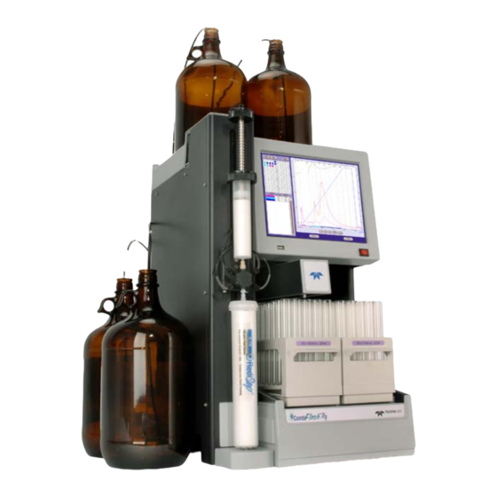
- Page 1 CombiFlash ® Installation Guide For indoor use only COPYRIGHT © 2002, 2004 by Teledyne Isco, Inc. 4700 Superior St., Lincoln, Nebraska, U.S.A. 68504 Phone: (402) 464-0231 Toll Free: (800) 228-4373 FAX: (402) 465-3022 Revision A: August 15, 2007 Part #60-5233-385...
-
Page 2: Table Of Contents
CombiFlash ® Installation Guide Table of Contents 1. Introduction 1.1 Documentation Overview ..... . 1-1 1.2 Product Overview ......1-1 1.3 Operating Overview . - Page 3 CombiFlash® R Installation Guide 3. Operation 3.1 Sample Preparation ......3-1 3.1.1 Liquid Sample Injection ....3-1 3.1.2 Solid Samples .
-
Page 4: Introduction
Once you are operating the CombiFlash R , you may refer to the Help menu for operating instructions and further assistance. The CD that accompanies this installation guide contains this ® guide in Adobe Acrobat PDF format and the PeakTrak On-line Help in PDF format. - Page 5 CombiFlash R system at the instrument, from a computer in the lab, or from remote locations. The CombiFlash R is optimized for use with Teledyne Isco’s ® RediSep columns, which are pre-packed with a variety of media. For example, the CombiFlash R...
-
Page 6: Operating Overview
A network connection allows control from a computer on an established network. Note Teledyne Isco recommends that you obtain assistance from your Information Technology department before attempting direct or network connections to a Windows computer. 1.3.1 Multiple Control Possibilities The system can be accessed from the built-in touch panel and up to ten network computers. -
Page 7: Specifications
CombiFlash® R Installation Guide 1.4 Specifications Table 1-1 Specifications Overall Dimensions Height: 61 cm (24") Width: 36 cm (14.1") Depth: 43 cm (17") Weight 24.5 kg (54 lbs) Input voltage range from 100 to 240 VAC, 2.0 Power Options Amps maximum... -
Page 8: Controls, Indicators, And Features
Section 1 Introduction 1.5 Controls, Indicators, and Features Figures 1-2 through 1-4 illustrate the controls on the CombiFlash R Figure 1-2 CombiFlash R Features (Front) 1. Touch Panel LCD display – Large 10.5 inch display for system monitoring and control. 2. - Page 9 CombiFlash® R Installation Guide 6. Racks and Collection Tubes – The racks hold the fraction collection tubes. Racks include an RFID tag which the system uses to read the rack type and collection tube size. 7. Sample Injection Port – Luer-type fitting to accept the sample though either a solid load sample cartridge (shown) or a liquid injection using a syringe or similar device.
- Page 10 Section 1 Introduction Figure 1-3 CombiFlash R Features (Side) 19 20 Figure 1-4 CombiFlash R Features (Back)
-
Page 11: Safety
CombiFlash® R Installation Guide 21. Optional External Gas Port – An inlet for an internal pump which supplies pressurized air or user-supplied gas for solvent level sensing, waste container full detection, and system/column purges. The external gas should be regulated to 2–5 psig before connecting the source to this port. -
Page 12: Hazard Severity Levels
OSHA Guide 1910.1000. To reduce those levels to a safe exposure, Teledyne Isco recommends that you place the system in a laboratory hood designed for the purpose of ventilation. This hood should be constructed and operated in accordance with federal state and local regulations. -
Page 13: Hazard Symbols
CombiFlash® R Installation Guide 1.6.2 Hazard Symbols The equipment and this manual use symbols used to warn of hazards. The symbols are explained in Table 1-2. Table 1-2 Hazard Symbols Warnings and Cautions The exclamation point within the triangle is a warning sign alerting you of important instructions in the instrument’s technical reference manual. -
Page 14: For Additional Information
1.7 For Additional Information Technical assistance for the CombiFlash R can be obtained from: Teledyne Isco, Inc. 4700 Superior St. Lincoln NE 68504 Phone: (800) 228-4373 or (402) 464-0231 Fax: (402) 465-3001 E-mail: IscoService@teledyne.com... -
Page 15: System Preparation
WARNING If there is any evidence that the system has been damaged in shipping, do not plug it into AC power. Contact Teledyne Isco or its authorized representative for advice. Compare the contents of the boxes with the enclosed packing slip. -
Page 16: Connect Power
CombiFlash® R Installation Guide WARNING The system is heavy. Use a two-person lift to prevent injury. Before making any connections to the CombiFlash R , place the system on the bench or in the fume hood where it will be operated. - Page 17 Section 2 System Preparation Figures 2-1 and 2-2 show the recommended connections when the user-supplied solvent container has a 38 or 45 mm opening (GL 38 or GL 45). Note that there are two different styles that can ship with the system. One styles includes a metal plate and larger opening on the cap (Figure 2-1), the other has no plate and a smaller opening on the cap (Figure 2-2).
- Page 18 CombiFlash® R Installation Guide To Solvent Supply To Solvent Level Sensing Connection 60-0923-017 Ferrule 60-0923-015 Compression Fitting Nut 60-5234-130 Label (1 of 4) 60-5235-050 38 mm Cap, or 60-5235-051 45 mm Cap 60-5234-129 Inlet Filter Assembly (Place weighted filter at bottom of container.)
-
Page 19: Connect Waste Lines
Section 2 System Preparation The Solvent Level Sensing air line connects to the back panel with a compression fitting. This fitting must be airtight. To connect tubing using the compression fittings: 1. Slide the nut and ferrule onto the tubing as shown in Figure 2-1 or 2-2. - Page 20 CombiFlash® R Installation Guide The Waste Level Sense uses air pressure to detect the liquid level in the common waste container. If using individual containers, use the waste level sense to detect the level of the Diverter Valve waste container. Under normal operating conditions it will fill faster than the Inject Valve waste container.
- Page 21 Section 2 System Preparation To Diverter Valve Waste Connection To Waste Level To Inject Valve Waste Sense Connection Connection 60-0923-017 Ferrule 60-0923-015 Compression Fitting Nut 60-5234-143 Waste Tubing Assembly 60-5234-051 38 mm Waste Cap, or 60-5234-142 45 mm Waste Cap Figure 2-3 Recommended waste connections, with metal plate...
- Page 22 CombiFlash® R Installation Guide To Diverter Valve Waste Connection To Waste Level To Inject Valve Waste Sense Connection Connection 60-0923-017 Ferrule 60-0923-015 Compression Fitting Nut 60-5234-143 Waste Tubing Assembly Ventilation Hole (Luer fitting) If necessary, connect user-supplied tubing and route to fume hood.
-
Page 23: Optional External Gas
Section 2 System Preparation 2.6 Optional External Gas The CombiFlash R system has an internal air pump that provides compressed air for solvent and waste level sensing. Optionally, the system can deliver a compressed gas. Inert or other gases may be more suitable than air for some applications. -
Page 24: Install Collection Tube Racks
CombiFlash® R Installation Guide 2.9 Install Collection Tube Racks Before beginning a run, you must load collection racks with tubes onto the system’s fraction collector tray. Your system was shipped with two collection tube racks. The following tube rack sets are available: •... - Page 25 Section 2 System Preparation When you turn the power switch to on, the system will automatically detect the type of rack, and configure program settings accordingly. Later, in section 2.11.6, you can configure the maximum volume for each tube size. Figure 2-5 Loading test tubes Tube Size Label...
-
Page 26: Turn On Power
CombiFlash® R Installation Guide 2.10 Turn on Power The system’s power switch is located just below the touch screen panel. Turn the switch to the ON position. The system will begin its startup routine which includes self diagnostics. The system is ready for operation when the PeakTrak screen is displayed. -
Page 27: General Settings
CombiFlash R will shut down to avoid a hazardous condition. Teledyne Isco recommends using the default setting of 25. This value represents an organic vapor level slightly above the ambient vapor level of a well-ventilated laboratory. A setting below 25 could cause random alarms without significant vapors present. -
Page 28: Automatically Print Report At End Of Run
CombiFlash® R Installation Guide • Ensure that there is no visible solvent leakage from the system. If PeakTrak continues to display the Vapor Limit alarm after you have made these checks and corrected any problems found, it is likely that organic vapors are present in the ambi- ent environment of your laboratory. -
Page 29: Set Default Tube Volumes
Section 2 System Preparation Original method Extension 2 Final Extension Extension 1 Extension 3 Minutes Figure 2-7 Automatic Run Extension Examples Figure 2-7 illustrates the possible run extensions. The original method was programmed to rise to the maximum %B over seven minutes, hold for two minutes and return to the minimum %B for a final minute. -
Page 30: Default Run Units
CombiFlash® R Installation Guide To prevent unauthorized time changes, this feature is password protected. The system is shipped with the password set to combiflash. Use the Tools>Set Password menu command to change this password for greater security. 2.11.8 Default Run Units Run units are displayed along the X-axis of the chromatogram. -
Page 31: Prime The Solvent Lines
Section 2 System Preparation 2.12 Prime the Solvent Lines Before the first use, the system should be primed. Ensure that the solvent containers are filled, then: 1. Select the “Tools>Auto prime” menu command. 2. Select the desired A and B solvents from the drop-down list boxes. -
Page 32: Operation
CombiFlash ® Installation Guide Section 3 Operation This section provides abbreviated operating instructions for the CombiFlash R . For complete instructions, refer to Help menu option from PeakTrak’s main menu. 3.1 Sample Preparation Before starting a run, consider how the sample will be introduced to the column media. - Page 33 CombiFlash® R Installation Guide remain bound to the media. Once dried, pour the media/sample mixture into an empty cartridge. To prepare an empty solid sample cartridge: 1. Ensure the empty cartridge has a bottom frit. CAUTION Missing frits may cause equipment damage, UV detection problems, or increased maintenance.
-
Page 34: Preloading On Column
Section 3 Operation 4. Press the tab on the cap and push the plunger into the cartridge until it rests against the top frit. 5. Release the tab on the cap. Note that the opposite end of the tab secures the cartridge. 6. -
Page 35: Start A Default Method
CombiFlash® R Installation Guide Note After loading a RediSep R column, the system will use RFID technology to automatically detect the media type and column size. PeakTrak displays the detected column size on the Main and Method Editor windows. If the system does not detect the column, manually select the column media and size. - Page 36 Section 3 Operation • Cartridge w/ (with) pause – Select this option if you intend place the sample into a solid sample load cartridge, but have not yet prepared the sample. When you click the run button, the system will perform a column equilibration and then wait while you prepare the cartridge.
-
Page 37: During The Run
CombiFlash® R Installation Guide 7. Click OK and the run begins. The system responds according to the sample Loading Type you selected in step 4. If you selected Cartridge w/ pause, the system equili- brates the column with the starting %B and then waits while you prepare the solid sample load cartridge. -
Page 38: Run Control Buttons
Section 3 Operation 3.4.1 Run Control Buttons You clicked the Play button to start the run. During the run, other run control buttons are active. • Pause — The Pause button holds the %B at the current value while the system continues to operate (sometimes called an isocratic hold). - Page 39 CombiFlash® R Installation Guide • Fast Forward — Click this button to jump to the next step of a run. Once you have started a run, the system performs several steps. The first step is to deliver solvents using the pro- grammed gradient for the entire run length.
-
Page 40: Remote Interfaces
CombiFlash ® Installation Guide Section 4 Remote Interfaces This section provides instructions for controlling the CombiFlash R system through a remote interface. The system can be accessed by several personal computers through a corporate network, or by a single personal computer (PC) through a direct connection. -
Page 41: Network Pc Access
CombiFlash® R Installation Guide • Is it possible to assign a static IP address based on the MAC address of the instrument? (Administrators may use this method to assign static addresses through the DHCP server instead of directly on the instrument, simplifying the management of static IP addresses within the organization.) -
Page 42: Network Printing
Section 4 Remote Interfaces • If the system was configured with an IP address, access the system from a network computer by entering “http://___.___.___.___”, where the blanks are replaced by the selected address. • If the system was configured for DHCP and a network name, access the system from a network computer by entering “http://____________”, where the blank is replaced by the Instrument Name. -
Page 43: Automatically Print Report At End Of Run
CAT5 network cables will not work. You can purchase a crossover cable locally or ask your Information Technology department to assemble one. You can also order a crossover cable (part number 480-6545-02) from Teledyne Isco. Note These instructions assume that the system is using the factory-set... -
Page 44: Windows 2000 Settings
Section 4 Remote Interfaces Note The following instructions may require a user account with Administrator privileges on the PC. If you cannot modify the settings in sections 4.2.1 through 4.2.3, contact your Information Technology department. 4.2.1 Windows 2000 Settings 1. From the Windows Start button, select “Settings>Control Panel”... -
Page 45: Windows Xp Settings
CombiFlash® R Installation Guide Figure 4-1 Local Area Connection Properties Window Figure 4-2 Internet Protocol Properties Window 4.2.2 Windows XP Settings 1. From the Windows Start button, open the Control Panel. 2. Locate the Network Connection icon and open this control... - Page 46 Section 4 Remote Interfaces 3. Highlight the “LAN or High-speed Internet Connection” icon. Select the “Change settings of this connection” option, or right-click and select “Properties.” Refer to Figure 4-3. 4. Highlight the “Internet Protocol (TCP/IP)” item in the list, and click on the “Properties”...
-
Page 47: Windows Vista Settings
CombiFlash® R Installation Guide Figure 4-5 Alternate Configuration Settings 7. Enter the Subnet Mask, “255.255.255.0.” 8. Click the OK button to close the Internet Protocol properties window. Click the Close button to close the Local Area Connection properties window. 9. Shut down the PC and place the CombiFlash R system in Standby. - Page 48 Section 4 Remote Interfaces Figure 4-6 Local Area Connection Properties Figure 4-7 Internet Protocol Version 4 (TCP/IPv4) Properties...
-
Page 49: Completing The Direct Connection
CombiFlash® R Installation Guide Note If the Internet Protocol Version 4 (TCP/IPv4) option is not listed, click the Install button to add it. If assistance is needed, press the F1 keyboard button to display Windows Vista Help. Note The following steps change the local area connection settings. If the PC must be restored to its original network configuration, record the present Internet Protocol (TCP/IP) settings now. -
Page 50: Maintenance
CombiFlash ® Installation Guide Section 5 Maintenance 5.1 Preventive Maintenance The system requires preventive maintenance for safe and reliable operation. Refer to the schedule below for the minimum periodic maintenance requirements. As Needed – Perform these tasks as conditions require: •... -
Page 51: Collection Rack And Tray Cleaning
CombiFlash® R Installation Guide CAUTION Do not immerse the instrument in a water bath. The instrument is not watertight and this action could damage the internal electronics. 5.2.1 Collection Rack and Tray Cleaning WARNING Risk of fire or equipment damage. Unclean collection racks and tray might inhibit their conductive properties. - Page 52 Section 5 Maintenance Vacuum or pressurized air applied to the outlet end of the drain tube must exist at the collection tray drain hole. Figure 5-1 Collector tray drain hole Vacuum or pressurized air applied to the outlet end of the drain tube must exist at the top shelf drain hole.
-
Page 53: Flow Cell Cleaning
CombiFlash® R Installation Guide 5.4 Flow Cell Cleaning 5.4.1 Post Separation As a preventive measure, all default column methods finish the separation run with a high percentage of solvent B (Figure 5-3). This brief time (two to three column volumes) of strong solvent flushes residual compounds from the column, flow cell, and internal tubing. -
Page 54: Quick Cleaning When Recommended
Section 5 Maintenance CAUTION When using methanol as solvent B with silica column media, do not pump more than 50% solvent B. Higher percentages of methanol might break down the silica structure, possibly causing obstructions in the flow path. 5.4.2 Quick Cleaning when Recommended When the lamp energy is lower than normal, the system will recommend flow cell cleaning (Figure 5-4) before starting a separation run. - Page 55 CombiFlash® R Installation Guide Figure 5-5 Raw Lamp Energy Gauge • Red – lamp energy is obstructed to a degree that the system might not reliably detect peaks. If you attempt to operate the system, peak collection will be forced to collect all. This prevents diverting desired compounds to waste.
- Page 56 (Table 5-1). Or, complete the steps in the Monthly Flow Cell Cleaning procedure (section 5.4.3). Note If the numerical values of the Raw Lamp Energy (Figure 5-5) do not change, or if the first number remains at zero, contact Teledyne Isco’s Technical Service department.
- Page 57 CombiFlash® R Installation Guide Table 5-1 Suggested Flow Cell Cleaning Solvents Solvent Description Methanol Miscible with most LC solvents. Methanol will force other solvents through the system so they will not interfere with the next sample. It breaks down the tertiary structure of silica and allows it to flush through.
-
Page 58: Monthly Flow Cell Cleaning
10. Perform the Quick Cleaning as Required (section 5.4.2) and monitor the Raw Lamp Energy. If the lamp energy is in the green or yellow range, return the system to operation. If the lamp energy is red, contact Teledyne Isco’s Technical Service department for assis- tance. -
Page 59: Electrical Troubleshooting
CombiFlash® R Installation Guide 5.5 Electrical Troubleshooting If your instrument stops working and the touch panel display is off, check the line cord connection. If the line cord is connected properly, check the fuses in the power input module located on the system’s rear panel. These... - Page 60 2004/108/EC -The EMC Directive 2002/96/E C – T he WE E E Directive 73/23/EEC – The Low Voltage Directive Manufacturer's Name: Teledyne Isco, Inc. Manufacturer's Address: 4700 Superior, Lincoln, Nebraska 68504 USA Mailing Address: P.O. Box 82531, Lincoln, NE 68501...
- Page 61 Name and amount of Hazardous Substances or Elements in the product Hazardous Substances or Elements Component Name (Pb) (Hg) (Cd) (Cr(VI)) (PBB) (PBDE) LCD Display Circuit boards Wiring Internal Cables Line Cord Stepper Motor Deuterium lamp Valve Body Name and amount of Hazardous Substances or Elements in the product O: Represent the concentration of the hazardous substance in this component’s any homogeneous pieces is lower than the ST/ standard limitation.
- Page 62 NE 68504, U.S.A. * This warranty applies to the USA and countries where Teledyne Isco Inc. does not have an authorized dealer. Customers in countries outside the USA, where Teledyne Isco has an authorized dealer, should contact their Teledyne Isco dealer for warranty service.
Need help?
Do you have a question about the Installation Guide and is the answer not in the manual?
Questions and answers