2gig Technologies GO!CONTROL User Manual
Hide thumbs
Also See for GO!CONTROL:
- Installation & programming manual (78 pages) ,
- Installation and programming technical training (110 pages) ,
- User manual (20 pages)

Subscribe to Our Youtube Channel
Related Manuals for 2gig Technologies GO!CONTROL


Summary of Contents for 2gig Technologies GO!CONTROL
-
Page 1: User Guide
USER GUIDE Go!Control WIRELESS SECURITY SYSTEM WARNING: OWNER’S INSTRUCTION NOTICE Not to be removed by anyone except occupant... -
Page 2: Table Of Contents
Emergency functions ... . . 21 Cancel Time......40 ©2013 2GIG Technologies Inc. All Rights Reserved. - Page 3 Go!Control Wireless Security System | User Guide Dialer Delay ......40 2-Way Voice......41 TelephoneRemote Control Answer .
-
Page 4: System Overview
One of the 32 User Codes functions as a Duress User Code. Controlling the system with this code gives the appearance of normal operation, but using it secretly sends a “duress” report to the Central Station to initiate a silent alarm call for help. • Voice announcements from the Control Panel: The system has a vocabulary of descriptive words that can be assigned to sensors so each has a unique announcement such as “front door” or “bedroom window” if desired. • Home automation with the built‐in Z‐Wave controller for remote controlling Z‐Wave enabled home appliances (optional feature). • Alarm history with system event log: Each alarm and system alert is logged into the system’s memory. These events can be displayed and reviewed at the Control Panel or remotely by the Central Station. • Real time clock and calendar shows on the system’s display and is used to time stamp items in the event log. NOTE: If installed in a commercial location, this Control Panel is intended for burglary protection only (and not for fire protection) and that burglary protection is limited to mercantile premises and not bank vaults. 2‐way voice communication: After an alarm, the system can automatically connect with a Central Station operator so they can converse with people in the premises. Remote control of the system over the telephone. Remote control of the system using a Web‐enabled device through the Internet (requires cellular radio option). Three optional 24‐hour emergency functions: Panic, Fire, and Emergency. These functions can be activated by buttons on the Control Panel, using wireless sensors, from the wireless keypad, or from portable pendant devices (such as the panic button remote). ©2013 2GIG Technologies Inc. All Rights Reserved. -
Page 5: Basic Operation
Go!Control Wireless Security System | User Guide BASIC OPERATION User Codes The system installer has already Following are general operational concepts programmed a Master User Code for your that your system supports. Understanding system. This code can be used to control the these concepts will help you to use your system as well as assign and change the security system to its fullest extent. other user codes. The Master User Code can also access several system setup settings in Sensor Types/Zones the User Toolbox. The system’s wireless sensors have been assigned to selected “types” (often called Alarms “zones”). The sensor type determines how When an alarm occurs, the Control Panel’s and when the system will react to a signal siren and an external siren (if installed) from the sensor. Some sensors are armed 24 sounds for a preset time. During alarms and hours a day, other sensors are only armed after disarming, the alarm history button when the system is armed. displays all the alarms that have occurred, and which sensors were involved. The alarm Smoke, Heat, and Freeze history clears the next time the system is ... -
Page 6: Control Panel Features
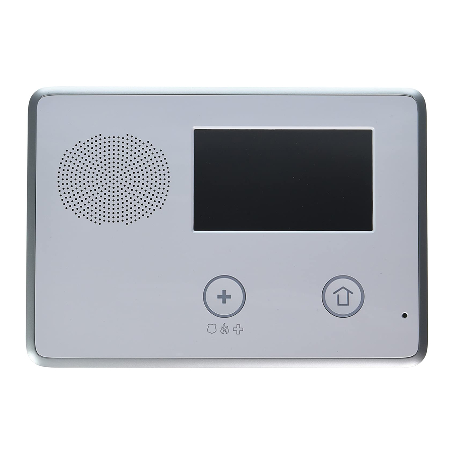
A Alarm Sounder and Speaker Sounds all system local alarms, voice prompts, system sounds, and audio for 2‐way voice communications with the Central Station B Color Display with Shows all system information, status, programming, and functions as Touchscreen the keypad. Display cycles clock, calendar, and weather (press manually to change) C Microphone For voice communication with the Central Station D Emergency Button/Indicator Lights White when enabled for emergency alarms. Flashes White during emergency alarms E Home Button/Indicator Sensor Status Lights Green when all sensors are closed (ready to arm) Not lit when any sensor is open (not ready to arm) Arming Status Lights Red when system is armed Flashes Red during the Entry Delay Alarm Memory Flashes Red during an alarm Flashes Red after an alarm while system is still armed Power Outage Flashes White during power outage (system on battery backup) Flashes Green when all sensors are closed (ready to arm) Flashes Orange when any sensor is open (not ready to arm) Flashes Red while system is armed ©2013 2GIG Technologies Inc. All Rights Reserved. -
Page 7: Main Display Screens
Go!Control Wireless Security System | User Guide MAIN DISPLAY SCREENS system status and arming buttons for Stay and Away. Optional check boxes for Entry The Control Panel is programmed and Delay and Silent Exit are displayed. operated using the color touch‐screen display. The display shows various buttons, indicators, and text to guide and inform you. The top bar on the display shows the current system mode, scrolling text of any pending alerts, and system status icons. Home Screen The Home Screen shows system status with icons to indicate system conditions. It also displays the time and date. The Home Screen Menu Screen has Security, Services, Silent Control and The Menu Screen shows the system status Display Off buttons. across the top of the screen and 3 main buttons: The Arm button and Toolbox button are always displayed. If the emergency option is set, an Emergency button is also displayed. Chime and Voice check boxes are also displayed. TIP: Services is a system option for controlling Z‐Wave devices, if not active, the button is not displayed. -
Page 8: Burglary Protection
BURGLARY PROTECTION When your system was setup by your installer, wireless sensors were placed to monitor specific doors and windows. The installer selected these doors and windows as likely places where an unlawful intrusion might occur and could be detected. Each sensor was programmed to have the system react in a specific way. See “Installer Programmed Options” on page 38 for specifics about each sensor. Some sensor types such as smoke detectors, carbon monoxide detectors, panic buttons, etc. are always active and can trigger an alarm at any time. Other sensors on protected doors and windows are part of the burglary protection part of the system, and can be turned on or off. Turning on the burglary protection part of the security system is called “Arming the System”. The burglary protection part of the system can be armed in two modes: Stay Mode or Away Mode. SAMPLE FLOOR PLAN Refer to the floor plan below. It shows a typical residential installation and the various types of wireless sensors and their functions. Front and side door sensors have Exit/Entry delay SMKE Smoke detector Side and main garage door sensors have Exit/Entry delay Carbon monoxide detector Control panel Glass break sensor Door/window sensor Wireless keypad Motion detector External siren This security system is in compliance with UL 681 (Burglar and Holdup Alarm NOTE: Systems) and UL 827 (Central Station Alarm Services). ©2013 2GIG Technologies Inc. All Rights Reserved. -
Page 9: Sensor Status
Go!Control Wireless Security System | User Guide SENSOR STATUS The security system constantly monitors all of the sensors attached to the protected doors and windows in your home or business. The Control Panel knows if each door or window with sensors is open or closed. The open or closed condition of the protected doors and windows is called the sensor status. For maximum security, all the doors and windows on your premises should be closed when you leave the building. In some cases, such as when using the security system when you stay at home, you may want to leave some doors or windows open. The system recognizes bypasses to resolve the open doors or windows. See "Manually Bypassing or Un‐bypassing Sensors" on page 10. NOTE: Before you can arm the system, you must close or bypass all doors and windows with sensors. NOTE: If installed in a commercial location, this Control Panel is intended for burglary protection only (and not for fire protection) and that burglary protection is limited to mercantile premises and not bank vaults. CHECKING THAT ALL SENSORS ARE CLOSED In most cases, you will be arming the security system with all of the sensor‐protected doors and windows closed. The Control Panel provides easy ways to verify that all the sensor‐ protected doors and windows are closed before arming the system: • The Home button lights green when all perimeter sensors are closed. The Home button is not lit if any perimeter sensor is open. Open interior sensors do not change this indication. -
Page 10: Viewingeach Sensor's Status
• The top of the display on the Home, Security, and Menu Screens sensor status. See “System Status Icons” on page 23. Pressing the Status button also displays a list of open sensors and general system status and alerts. A The Status Bar shows the system mode and shows system status icons. See “System Status Icons” on page 23. B The Arm button on the security and menu screens lights green when all perimeter sensors are closed. The Arm button lights orange if any perimeter sensor is open. C The Home button lights green when all perimeter sensors are closed. The Home button is not lit if any perimeter sensor is open. D The icon displayed shows that an interior sensor is open. Other icons can appear here as well. See “System Status Icons” on page 23. Dealing with a sensor False Alarm The Control Panel reports alarm conditions on all sensors when armed both visually (on the status bar, and through a system alert icon) and audibly (through voice and chime announcements). There are times, though rare, that an sensor will send an alarm condition to the Control Panel when no alarm exists. The conditions of a false alarm vary depending on the type of sensor and how that sensor communicates with the Control Panel. • Perform a System, Sensor, and Panel Test to find any false alarm conditions. See "System Test" on page 31. See "Sensor Test" on page 31. See "Panel Test" on page 32. ©2013 2GIG Technologies Inc. All Rights Reserved. -
Page 11: Sensor Bypassing
Go!Control Wireless Security System | User Guide SENSOR BYPASSING NOTE: Bypassed sensors offer no protection and cannot cause an alarm. Use bypass if Before the system can be armed, all you want to arm your system with one or protected doors and windows must be more sensors open and intentionally closed or bypassed. You can bypass open unprotected. sensors on protected doors or windows before arming the system. When a sensor is Force Bypassing Sensors bypassed, the system ignores that the door If any sensors are open when the Arm or window is open. There are two types of button is pressed, the Control Panel displays sensor bypasses available: the bypass sensor screen. When the system • Forced is disarmed, the force bypassed sensors are • Manual returned to normal. In some cases (such as when using the With one or more perimeter sensors security system for protection when staying open, press Arm from the Security or at home) it may be desirable to leave some ... -
Page 12: Stay Mode
Silent Control in Stay Mode using a predetermined door and disarm the Three options for silencing the beeps and system before an alarm is triggered. When announcements are available when arming arming the system in Stay Mode, an Entry or disarming the system in Stay Mode. Delay option check box is shown on the Control Panel’s Arming Screen. • On the Control Panel’s Home and Security Screens, a Silent Control button is displayed. • On the Arming Screen, a Silent Exit check box is displayed. • On the Exit Delay Screen, a Silence button is displayed. Selecting any of these options silences the Control Panel beeps and announcements, and when arming, selecting the option Normally this option check box is checked, doubles the length of the Exit Delay. so the programmed delay doors allow time for disarming the system after the door is ©2013 2GIG Technologies Inc. All Rights Reserved. -
Page 13: Armingto Stay Mode
Exit and Entry Delays in Away or press Bypass All to force bypass the Mode displayed sensors. Certain sensors, such as a door, can be setup NOTE: Bypassed sensors do not trigger an by your installer to have a delay before alarm. (To bypass sensors, enter a User triggering an alarm. This provides a way for Code unless the installer has set the an authorized person to exit and reenter the system for Quick Bypass). premises without triggering an alarm. On the Arming Screen, use the Entry • Exit Delay allows time to leave after Delay check box option in Stay Mode. arming the system. • Entry Delay allows time to enter and If no one is expected to re‐enter, the disarm the system before an alarm is system can be armed without an Entry triggered. Delay. All perimeter doors will trigger the alarm instantly. To arm with all exit/ ©2013 2GIG Technologies Inc. All Rights Reserved. -
Page 14: Exit Delay Restart
Go!Control Wireless Security System | User Guide When arming the system in timer to allow someone to exit or enter Away Mode, an Entry Delay through a sensor‐protected door check box is shown on the programmed for delay without having to Arming Screen. By default, disarm the entire system. When the delay this option is checked, so the timer runs out, the system returns to the programmed delay doors allow time for normal Away Mode. disarming the system after the door is TIP: If interior sensors are installed in the opened. If you un‐check this box, the system in certain areas, do not violate delayed alarm trigger is removed from all those sensors when using the Quick Exit sensor‐protected doors programmed for feature in Away Mode. delay. Those entrances instantly trigger an alarm if they are opened in Away Mode. Auto Stay Mode NOTE: With the Entry Delay disabled, you The system may have been programmed by must remotely disarm the system with a the installer for Auto Stay Mode. If this wireless key fob before entering. option is on and the system is armed in Away ... -
Page 15: Disarmingthe System
• The system can be armed without an its ability to warn you if an alarm has Entry Delay. All perimeter doors trigger occurred while you were away. If an alarm the alarm instantly. The system has to be was triggered while the system was armed, disarmed with a wireless key fob. To arm the alarm siren runs for a preset length of with all exit/entry perimeter doors as time then stops. When you enter to disarm instant, un‐check the Entry Delay option the system, instead of sounding the normal button. Entry Delay beeps, the Control Panel sounds Press Away. repeated fast beeps to warn you that an To arm the system, enter a User Code if alarm has occurred while you were away. your installer has turned off the system’s When you enter your home to Quick Arming feature. disarm the system, if you hear The system arms and shows the Exit fast repeated beeps instead of Delay counting down. When the Exit the normal entry delay beeps, Delay expires, the system is fully armed Use Extreme Caution! An intruder may in the Away Mode. still be present inside the building! Wait outside and use a Cell Phone to call law enforcement for assistance. ©2013 2GIG Technologies Inc. All Rights Reserved. -
Page 16: Disarmingfrom Stay Mode
Go!Control Wireless Security System | User Guide Disarming from Stay Mode Delayed sensors start the Entry Delay to allow time to disarm the system. Instant Disarm the system from Stay Mode before sensors trigger the alarm right away. Most exiting the premises. sensors trigger the alarm siren, some From the Security Screen, press for sensors may be set to trigger a silent alarm Silent Control. without sounding the siren. From the Security Screen or the Menu Screen, press Disarm. This action Burglary Alarm Siren displays the Disarm Code Screen. If there is a burglary alarm tripped while the system is armed, the Control Panel sounds the alarm siren for a preset time (see "Installer Programmed Options" on page 38). After the time expires, the siren will stop sounding. The system limits the number of times a sensor can re‐trigger an alarm while the system is armed. The setting is one to six times per sensor, per arming period (see The left side of the screen shows any "Installer Programmed Options" on page 38). -
Page 17: Optional2 Way Voice Communications
To arm the system to Away Mode using a and not be able to talk. This is for your key fob, press the button. protection. NOTE: Depending on setup options, if there are open perimeter doors or windows, the system may not allow arming to Away Mode with a wireless key fob. See “Installer Programmed Options” on page 38. Key Fob Disarming • Using a key fob to disarm the system from Stay or Away Mode, press the Disarm button. NOTE: To use your key fob to disarm your system, this option must already be enabled by your installer. Key Fob Emergency • To trigger an emergency alarm using a key fob, press the Away button and Disarm button at the same time for 5 seconds. ©2013 2GIG Technologies Inc. All Rights Reserved. -
Page 18: Key Fob Auxiliary
Go!Control Wireless Security System | User Guide WIRELESS KEYPAD NOTE: If an emergency alarm is triggered by a key fob, it cannot be stopped using the ARMING TO AWAY MODE key fob Disarm button. The alarm must To arm the system to Away Mode using a be canceled at the Control Panel. wireless keypad, enter a User Code. Key Fob Auxiliary Press the Away button. • To trigger the Control Panel’s auxiliary If Quick Arming has been programmed output, press the Auxiliary button. by your installer, just press the Away button If you use the Auxiliary button, the auxiliary output controls the _________________... NOTE: If there are open perimeter doors or windows, the system does not allow Arming to Away Mode with a wireless WIRELESS KEYPAD keypad. All open sensor‐protected doors ARMING AND DISARMING and windows must either be closed or ... -
Page 19: Smoke, Heat And Freeze Protection
Fan the detector for 30 seconds to clear This action triggers the fire alarm the detector’s sensor chamber. sounders and sirens. You can trigger the fire alarm from the wireless keypad by After the problem has been corrected, holding down the Fire button. Both of from the Alarm Memory screen, check these actions causes the fire alarm Clear Alarm History, then press Ok. sounders and sirens. NOTE: You cannot clear Fire and CO sensors Evacuate all occupants from the that are still violated from the Alarm premises and call your local Fire Memory Screen. Only when the Fire Department from a safe location outside Alarms and CO Detectors return to your home. normal operation. Fire Alarm Sounds Automatically Carefully inspect your premises for fire, heat or gas if your Fire Alarms and CO If the fire alarm sirens are sounding, do the Detectors remain in alarm state. following: ©2013 2GIG Technologies Inc. All Rights Reserved. -
Page 20: Recommended Fire Alarm Locations
Alarm Code, ANSI/NFPA 72, (National Fire Protection Association, Batterymarch Park, Quincy, MA 02269). Printed information describing proper installation, operation, testing, maintenance, evacuation planning, and repair service is to be provided with smoke detectors and alarms. National Fire Protection Association Standard #72 The National Fire Protection Association’s (NFPA) Standard #72 recommends the following placement for smoke detectors: Early warning fire detection is best achieved by the installation of fire detection equipment in all rooms and areas of the household. The equipment should be installed as follows: • Install a smoke detector outside each separate sleeping area, in the immediate vicinity of the bedrooms and on each additional story of the family living unit, including basements and excluding crawl spaces and unfinished attics. Also install smoke detectors in the living room, dining room, bedrooms, kitchen, hallway(s), finished attics, furnace room, utility and storage rooms, and attached garages. A Mount a smoke alarm between the sleeping area and the rest of the family unit. B In family units with more than one sleeping area, mount a smoke alarm to protect each sleeping area. C Example of a residence that has required and optional areas for smoke alarms. D For houses with multiple stories, mount a smoke alarm on each story. Indicates an optional smoke alarm if a door is not provided between the Living and the Recreation rooms. Indicates a required smoke alarm. ©2013 2GIG Technologies Inc. All Rights Reserved. -
Page 21: Emergencyaction Plan
Go!Control Wireless Security System | User Guide Where NOT to Mount the Alarm • Directly above a sink, cooker, stove or oven • Do not locate alarm within 5 feet (1.5 m) of any cooking appliance • Next to a door or window that would be affected by drafts (extractor fan or air vent) • Outside • In or below a cupboard • Where air flow would be obstructed by curtains or furniture • Where dirt or dust could collect and block the sensor • Where it could be knocked, damaged, or inadvertently removed Fire‐warning equipment for residential occupancies are capable of protecting about 50% of the occupants in potentially fatal fires. Victims include the elderly, children, and the physically or mentally impaired. Victims include any person that cannot escape even when warned early enough that escape should be possible. For these people, other strategies such as protection‐ in‐place or assisted rescue or escape would be necessary. • Studies show that Smoke/Heat/Freeze Alarms may not awaken all sleeping individuals. It is the responsibility of individuals in the household that are capable of assisting others to provide assistance to those who may not be awakened by the audible alarm or those who may be incapable of safely evacuating the area unassisted. •... -
Page 22: Emergency Functions
Fire • Emergency You can activate emergency functions using the Control Panel as well as wireless sensors, wireless keypads or from portable pendant devices such as the panic button remote. The button displays the emergency screen. Just pressing the button does not trigger an alarm. During the installation, your installer programmed the emergency buttons that are displayed on the Emergency Screen. If, however, no emergency functions are available, an information screen displays. To see which emergency functions are available on your system, press the button. In the event of an emergency, press and hold the emergency button for at least 2 seconds to activate the alarm. A If emergency functions are available, the Emergency button is a solid white lighted button. B To display the Emergency Screen, press the Emergency button. C The Emergency Screen. D The Emergency Screen displays the emergency options that are available on your system. Panic The panic (or police) button sends an immediate panic report to the Central Station. During installation, the installer either set the system to sound the siren when the button is pressed, or to not sound the siren, but to trigger a silent alarm. Fire The Fire button send an immediate fire report to the Central Station. The Control Panel sounds the fire horn when the button is pressed. Emergency The emergency button sends an immediate report to the Central Station. The Control Panel sounds the siren when the emergency button is pressed. ©2013 2GIG Technologies Inc. All Rights Reserved. -
Page 23: System Trouble Alerts
10pm to 9am. Any trouble alerts will still be Trouble Alert Icon displayed and reported (if enabled), but the If the system detects trouble, it flashes the sounder does not beep during nighttime trouble alert icon on the Security Screen hours. Some trouble conditions may clear and sounds 6 alert beeps every minute. automatically while other trouble conditions Scrolling text along the top of the display may require service to correct. If a trouble also describes the trouble condition. condition still exists after 9am, the sounder The trouble alert icon displays a number beeps to indicate trouble. in the upper right corner that is the number NOTE: Regardless of whether the trouble of current trouble alerts. alert sounder is suppressed or not, every The trouble alert icon flashes until the trouble condition is always displayed on trouble alerts are acknowledged, then it the trouble alert list and recorded in the remains constantly lit until all the troubles system history event log. are corrected. When all troubles are corrected, the icon disappears completely. ©2013 2GIG Technologies Inc. All Rights Reserved. -
Page 24: System Status Icons
Radio Modem Icon If the system’s optional Cell radio modem is installed, the cell radio icon is displayed on the status bar while the cell radio is being used to update software or add features. AC Power Icon The AC power icon displays whether the Control Panel is receiving AC line power or not. House Icon If an interior sensor is open (or a motion detector has just been activated) the status bar displays the House icon or Interior Phone Line Failure Icon Sensor Open Icon. If the system detects a telephone line failure, the Phone Line Failure Icon is displayed. NOTE: During arming, the House Icon flashes as a warning. Backup Battery Status Icon If the Control Panel’s backup battery tests low or exhausted, the Backup Battery Status Icon is displayed. ©2013 2GIG Technologies Inc. All Rights Reserved. -
Page 25: Messaging
Urgent (yellow message icon) • Emergency Priority (red message icon) Up to 31 text messages can be stored in the Control Panel’s memory. You can review them through the Control Panel’s display. Displayed messages are sorted in the following manner: • Type • Date Press Back to return to the message list, • Alphabetically or press Delete to erase the message. NOTE: If you check the Mark Read box, the message remains on the message list (If you decide not to delete it), but it no longer displays in bold. When deleting a message, a confirmation screen displays. Press Delete Message, or to return to the message, press Cancel. Displaying Messages When a message is sent to the Control Panel, 3 beeps sound and the message icon displays on the Security Screen. Standard messages display a blue message icon with a number of unread messages in the upper ©2013 2GIG Technologies Inc. All Rights Reserved. -
Page 26: Readingcon Dential Messages
Sorting Messages On the Code Entry Screen, Enter the To select the order in which messages are Master User Code. Regular User Codes displayed on the message list, use the are not accepted. Message Sort Screen. To display the Message Sort Screen, press Sorts. View the displayed message. As detailed in "Reading Messages" on page 24, either save or delete. To sort the messages, pick from the Filtering Messages following options: To select the type of messages that are • Date received displayed on the message list, use the • Date expired Message Filter Screen. • Alphabetically To reverse the display order, check the Reverse box. To list urgent messages first, check the Priority box. To return to the message list, press Back. When the message reviewing session is over, the sort options will reset. ©2013 2GIG Technologies Inc. All Rights Reserved. -
Page 27: Remote Control By Telephone
Remotely remotely arm the system. Talk to your dealer to see if your system was TIP: The Auto Stay feature (if enabled) does installed with the POTS module. Once you not function when you remotely arm the are connected with the system via the system. telephone, you can check on system status Bypassing Sensors Remotely and remotely control the major functions. If there are open sensors when you try to TIP: The announcements that the system arm the system remotely, the system plays over the telephone do not sound announces the current status and asks: “To out of the Control Panel’s speaker. bypass sensors and arm, press pound.” After the Control Panel answers, it s asks To bypass all open sensors and arm the for your User Code. You have 15 seconds system, press #. to enter your User Code using the telephone keys. If you don’t enter a valid After the open sensors are bypassed, the User Code in 15 seconds, the system system arms in the mode you selected and disconnects the call. announces the system status to you. ©2013 2GIG Technologies Inc. All Rights Reserved. -
Page 28: System Toolbox
You can setup User Codes with one or more On the Toolbox Screen (1 of 3), press Access Schedules. Access Schedules limit User Management. access to your system to people with User Codes such as maintenance personnel, service, or cleaning personnel. The Users Management Screen displays 3 users at a me. Use the ↓ and ↑ arrows to scroll through the list. Adding or Editing User Access Schedules ADDING A USER CODE If you selected By Schedule for the User Code, the Edit Schedules button IMPORTANT: User Codes 0000 and 0001 are appears. not permitted. To select or edit an existing User Code Press one of the Add User buttons. Access Schedule, press Edit Schedules. Enter a four‐digit code for the new User Code and press Ok. ©2013 2GIG Technologies Inc. All Rights Reserved. -
Page 29: Recurringuser Access Schedules
Go!Control Wireless Security System | User Guide You can also create a new user schedule Press the left and right time buttons to from the Edit Schedule screen. set the start and end times that this User Code is valid on that date. The User Access Schedules Screen displays all current schedules for the Press Ok to accept the schedule, or User Code. Cancel to return to the Schedule Type Screen. To add a new schedule, press Add Schedule or to edit a schedule, press an Date Range User Access existing schedule. Schedule You can select 1 of 3 Schedule types: For the Schedule type, select Date • Recurring Range. • Date • Date Range • Recurring applies to the days of the week and time period that this User Code is valid. •... -
Page 30: Changing A User Code
User Access Schedule Screen. the User Code that was deleted. Press A second screen confirms that the schedule was deleted. Press Ok. Changing a User Code From the User Management Screen, press the User button to change the User Code. Ensure that the currently selected User Code (or Pin number) appears, and press Change Pin. You can change the Master User TIP: Code, but you cannot delete it. Duress User Code Setup The Duress User Code (User Code #8) initiates a silent alarm for help by secretly sending a Duress report to the Central Station. Enter a new four‐digit User Code (or Pin Use the Duress Code when someone is number) and press Ok. forcing you to operate your security system against your will. When you use the Duress Code, a silent report is immediately sent to the Central Station and they will dispatch help. ©2013 2GIG Technologies Inc. All Rights Reserved. -
Page 31: Secret Duress Button
Go!Control Wireless Security System | User Guide entry screen. Enter the Duress User Code Setting the Duress User Code and a silent duress report is sent to the On the User Management Screen, press Central Station and they will dispatch help. the User 8 (Duress) button. The system remains disarmed. A confirmation screen appears: Press Create Duress User. SYSTEM HISTORY The Control Panel keeps a log of system events in the order in which they occur. Each event is marked with the date and time that the event occurred. To make reading the log easier, the system history display can be filtered to show selected events only. The events that can be filtered for the system history log display are: • Arm or Disarm of the system Enter a four‐digit code for the new • Bypasses of sensors (force bypasses and Duress User Code and press Ok. manual bypasses) To confirm the Duress User Code, enter • Alarms (alarms are displayed with a red ... -
Page 32: System Test
From the list of sensors, choose each test the system. While the system is in test sensor (Use the ↑ and ↓ arrows to mode, a “T” icon blinks on the upper right of scroll through the list). the display. Go to each sensor listed, and trigger it. • For door or window sensors, open and close the door or window. • For motion detectors, stay out of the protected area for five minutes, then walk through the area. • For portable sensors and wireless keypads, press a button. • For smoke, CO, or glass break detectors, press the detector’s test button. IMPORTANT: Test your Security System TIP: When a red bar is displayed for a sensor, weekly to ensure continued protection it has failed. and proper system operation. To test the system, do the following: From the Home Screen, press Security. From the Security Screen, press Menu. From the Menu Screen, press Toolbox. To access system test, enter the Master User Code. ©2013 2GIG Technologies Inc. All Rights Reserved. -
Page 33: Panel Test
Go!Control Wireless Security System | User Guide When all sensors have been tested. A To access the Toolbox, enter the Master User Code. confirmation screen appears. Use the ← and → arrows to select Panel Test Toolbox Screen (3 of 3). The panel test checks the Control Panel’s On the Toolbox Screen (3 of 3), press indicators and sounder. Telephone Test. A list of panel tests appears on the To begin the test enter the Master User Code again. Panel Test Screen. Use the ↑ and ↓ arrows to scroll through the list. Press each test button and answer Yes or No to the test question. Press Ok when all panel questions have been answered. A confirmation screen appears. To exit System, Sensor, and Panel Testing, press Ok. The system displays the Telephone Test Telephone Test Status Screen. The top part of the screen If your security system is connected to shows each function that is being tested. your telephone line it can communicate Use the ↑ and ↓ arrows to scroll with the Central Station using your ... -
Page 34: Chime Options
Note the Chime and Voice check boxes each function that is being tested. on the Menu Screen. The Chime check box button is a toggle that turns the Use the ↑ and ↓ arrows to scroll chimes on or off for all the system’s through the status messages. The sensors. The Voice check box button is a bottom part of the screen shows the toggle that turns the voice results of each test. announcements for the system’s If any tests fail, note what messages messages on or off (except alarm voice were displayed, and contact your alarm messages). installer to troubleshoot your system. From the Menu Screen, press Toolbox. After the testing is complete, press Ok to Enter the Master User Code to access return to the Toolbox. the toolbox. From the Toolbox Screen (1 of 3), press CHIME OPTIONS Chime Setup. The Chime Setup Screen On doors and windows monitored by displays each of the installed sensors sensors, the system can sound a chime to announce that the door or window was opened. Sensors can also be set to have the Control Panel say the name of the opening. ©2013 2GIG Technologies Inc. All Rights Reserved. -
Page 35: Brightness/Volume
Go!Control Wireless Security System | User Guide that can chime and the option currently From the Menu Screen, press Toolbox. set for the sensor. Enter the Master User Code to access the toolbox. To change the sensor’s chime options, press the sensor button. From the Toolbox Screen (1 of 3) press There are 14 chime options for TIP: Brightness/Volume. You can set the each sensor. brightness using the top bar. Adjust the level from 1 to 12 using the buttons on each end of the bar. You can set the speaker volume for the chimes and announcements on the bottom bar. Adjust the level from 1 to 12 using the buttons on each end of the bar. The volume setting does not effect the alarm sounder volume. When you are finished, press Ok. Check the option that you want for the sensor, then press Ok. BACKLIGHT TIME-OUT When you are finished, press Back. The backlight time‐out sets the length of Chime Options time that the display stays lit after use. You 1 Disabled Ding‐dong with Voice #3... -
Page 36: Displaycleaning
System Toolbox From the Toolbox Screen (2 of 3), press time. When the timer expires, the Backlight Time‐out. system returns to the Toolbox Screen. Choose one of the display backlight times and press Ok. DISPLAY CLEANING There is a special option for the Control Panel that enables you to clean the touch screen display. The option locks the display for 30 seconds so it can be cleaned without sensing any button presses. Clean the display with a dry, soft cloth. To lock the display for cleaning, do the following: From the Home Screen, press Security. From the Security Screen, press Menu. From the Menu Screen, press Toolbox. To access the toolbox, enter a valid User Code. From Toolbox Screen (1 of 3), press the → arrow. From the Toolbox Screen (2 of 3), press Clean Screen. The Display Cleaning Screen appears for 30 seconds. It shows the time remaining. The touch screen is locked during this ©2013 2GIG Technologies Inc. All Rights Reserved. -
Page 37: Touch Screen Calibration
Go!Control Wireless Security System | User Guide TOUCH SCREEN SET DATE AND TIME CALIBRATION The Control Panel has a built‐in clock and calendar. The Home Screen displays the time To calibrate the display, do the following: and date. The time and date are also used From the Home Screen, press Security. for the system history and event logs that From the Security Screen, press Menu. store data on system events. From the Menu Screen, press Toolbox. NOTE: During installation, your installer can set the system to automatically adjust for To access the toolbox, enter a valid User daylight saving time if it’s observed in Code. your location. From Toolbox Screen (1 of 3), press the → arrow. NOTE: The time and date are automatically set through the cellular radio by the From the Toolbox Screen (2 of 3), press Central Station if your Control Panel has Calibrate Touch Screen. a cellular radio installed. To set the date and time, do the following: From the Home Screen, press Security. -
Page 38: Displayfirmware Version
System Toolbox DISPLAY FIRMWARE VERSION To troubleshoot your system, you can check the firmware version that has been installed. To display the firmware version, do the following: From the Home Screen, press Security. From the Security Screen, press Menu. From the Menu Screen, press Toolbox. From Toolbox Screen (1 of 3), press the → arrow. From Toolbox Screen (2 of 3), press Version. When finished, press Back. ©2013 2GIG Technologies Inc. All Rights Reserved. -
Page 39: Installer Programmed Options
Fire Horn Run Time • 45 Seconds is the default, or _________ If there is a fire or carbon monoxide alarm, For ________ Door the Control Panel sounds the fire alarm horn for a preset time. After the time expires, the 24-Hour Emergency Functions fire alarm horn will stop sounding. Three 24‐hour emergency functions: You can 4 Minutes is the default, or the following: activate the Panic, Fire, and Emergency 8 Minutes buttons on the Control Panel. The installer 12 Minutes can set which emergency buttons on the 16 Minutes Control Panel are active. Unlimited Panic (Audible) Panic (Silent) Fire Emergency ©2013 2GIG Technologies Inc. All Rights Reserved. -
Page 40: Quick Arming
Go!Control Wireless Security System | User Guide Quick Arming Auto Stay Quick Arming allows you to arm your system The Auto Stay option will change the arming without having to enter a User Code. When mode if no one exits after arming the system you press the Stay or Away button, the in Away Mode. When the system is armed in system will start to arm without requesting a the Away Mode the Exit Delay will begin. User Code. With the Auto Stay option on, if a designated exit/entry door does not open and close • during the Exit Delay, the system • will arm in the Stay Mode instead of the Away Mode. Quick Bypass • Normally sensors that are open at the time • the system is armed will require force bypassing by entering your User Code. The system can be set so a User Code is not Key Fob Arm/Disarm Sound required to bypass open sensors when the ... -
Page 41: Key Fob Options
Go!Control Wireless Security System | User Guide Key Fob Options expires, will restart the Exit Delay timer, giving you the full length of time to leave The installer selects which options are again. The restart option only works once, enabled for each key fob (1‐8) used with the each time the system is armed. system. Refer to the table below for the options selected for your key fobs: • • Options 1 2 3 4 5 6 7 8 Arm without Exit Delay Allow key fob disarming Cancel Display Enable key fob auxiliary key A “cancel” message will be sent to the Central Station if the system is disarmed within a preset period of time after an alarm Options 1 2 3 4 5 6 7 8 is triggered. The system can be set to display ... -
Page 42: 2-Way Voice
Go!Control Wireless Security System | User Guide many cities impose when police respond to a false alarm. Your installer also can program the system for no dialer delay. NOTE: The dialer delay is also known as the abort window. It gives you time to disarm, but doesn’t delay the siren from sounding. Disarming during the abort window can display a cancel message depending on the Cancel Display setting (see "Cancel Display" on page 40). • 30 Seconds is the default, or ______ Seconds 2-Way Voice The system can connect with a Central Station operator so they can converse with people on the premises after an alarm. The 2‐way voice option allows communication to and from the Control Panel and the Central Station. 2‐way voice communications will occur after the system has made its alarm report. Your installer sets which sensors can trigger the 2‐way voice option. • • Telephone Remote Control Answer Your installer selects whether your system supports the remote telephone option or ... -
Page 43: Installer Specific Information
User 25 Zone 28 User 26 Zone 29 User 27 Zone 30 User 28 Zone 31 User 29 Zone 32 User 30 Zone 33 User 31 Zone 34 User 32 Zone 35 IMPORTANT: If you have logged user codes Zone 36 here, to maintain security, keep this Zone 37 guide in a secure location! Zone 38 Zone 39 Zone 40 Zone 41 Zone 42 Zone 43 Zone 44 Zone 45 Zone 46 Zone 47 Zone 48 ©2013 2GIG Technologies Inc. All Rights Reserved. -
Page 44: Service Information
SERVICE INFORMATION Your local Alarm dealer is the person best qualified to service your alarm system. Be sure to set up a routine service schedule with your local Alarm installer. THIS EQUIPMENT MUST BE CHECKED BY A QUALIFIED TECHNICIAN AT LEAST EVERY 3 YEARS. Important Power Supply Notice The Control Panel is powered by a plug‐in power supply. In case the power supply becomes unplugged, be sure to plug the power supply into an un‐switched receptacle. Do not connect the power supply to a receptacle controlled by a switch. ©2013 2GIG Technologies Inc. All Rights Reserved. -
Page 45: Regulatory Information
The jacks and plugs are designed to be must not be made. Doing so voids warranty. connected to a compatible modular jack that This equipment must not be used on is also compliant. See the Install Guide for telephone company provided public coin details. service. Connection to party lines is subject A ringer equivalence number code (REN) is to state tariffs. Contact your state public used to determine the quantity of devices utility commission for information. This that may be connected to the telephone equipment is hearing compatible (HAC) to line. Excessive RENs on a telephone line may any HAC compatible attached handset result in the devices not ringing in response telephones. to an incoming call. In most, but not all areas, the sum of the RENs should not exceed five (5.0). To be certain of the ©2013 2GIG Technologies Inc. All Rights Reserved. -
Page 46: Alarm Dialing Equipment
If you have any questions concerning these WIRELESS PRODUCT instructions, you should consult your NOTICE telephone company or a qualified installer about installing the RJ31X jack and alarm Radio controls provide a reliable dialing equipment for you. communications link and fill an important need in portable wireless signaling; however, Alarm Installation Notes to there are some limitations which must be Installer observed. For products equipped with an RJ31X jack For U.S. installations only: The radios are the line seize feature shall be verified. Be required to comply with FCC Rules and certain the local telephone and incoming Regulations as Part 15 devices. As such, they line connections are not reversed. These have limited transmitter power and lines are not reversed if the alarm dialer can therefore limited range. communicate with the central station. A receiver cannot respond to more than one transmitted signal at a time and may be ©2013 2GIG Technologies Inc. All Rights Reserved. -
Page 47: Fcc & Industry Canada Regulatoryinformation
Go!Control Wireless Security System | User Guide blocked by radio signals that occur on or l’appareil ne doit pas produire de brouillage, near their operating frequencies, regardless et (2) l’utilisateur de l’appareil doit accepter of code settings. tout brouillage radioélectrique subi, même si le brouillage est susceptible d’en Unauthorized changes or modifications compromettre le fonctionnement. could void the user’s authority to operate the equipment. These limits are designed to provide reasonable protection against harmful Infrequently used radio links should be interference in a residential installation. This tested regularly to protect against equipment generates uses and can radiate undetected interference or fault. radio frequency energy and if not installed A general knowledge of radio and its vagaries and used in accordance with the should be gained prior to acting as a instructions, may cause harmful interference wholesale distributor or dealer, and these to radio communications. However, there is facts should be communicated to the end no guarantee that interference will not occur users. in a particular installation. If this equipment does cause harmful interference to radio or television reception, which can be FCC & INDUSTRY CANADA determined by turning the equipment off ... - Page 48 CAUTION: Users should not attempt to make such connections on their own, but should contact the appropriate electric inspection authority, or electrician, as appropriate. The Ringer Equivalence Number (REN) is an indication of the maximum number of devices allowed to be connected to a telephone interface. The termination of an interface may consist of any combination of devices subject only to the requirement that the sum of the RENs of all the devices not exceed five. L’indice d’équivalence de la sonnerie (IES) sert à indiquer le nombre maximal de terminaux qui peuvent être raccordés à une interface téléphonique. La terminaison d’une interface peut consister en une combinaison quelconque de dispositifs, à la seule condition que la somme d’indices d’équivalence de la sonnerie de tous les dispositifs n’excède pas cinq. Refer to the equipment label for the unit’s load number or REN number. This device complies with Industry Canada license‐ exempt RSS standard(s). Operation is subject to the following two conditions: (1) this device may not cause interference, and (2) this device must accept any interference, including interference that may cause undesired operation of the device. ©2013 2GIG Technologies Inc. All Rights Reserved.
-
Page 49: Important Notice
Central Station may be out of service or first floor or basement fire. Moreover, temporarily out of service. Telephone smoke detectors have sensing lines are also subject to compromise by limitations. No smoke detector can sense sophisticated intruders. every kind of fire every time. In general, • Even if the system responds to the detectors may not always warn about emergency as intended, however, fires caused by carelessness and safety occupants may have insufficient time to hazards like smoking in bed, violent protect themselves from the emergency explosions, escaping gas, improper situation. In the case of a monitored storage of flammable materials, alarm system, authorities may not overloaded electrical circuits, children respond appropriately. playing with matches, or arson. Depending upon the nature of the fire • Alarm warning devices such as sirens, and/or the locations of the smoke bells or horns may not alert people or detectors, the detector, even if it wake up sleepers if they are located on operates as anticipated, may not provide the other side of closed or partly open doors. If warning devices sound on a ©2013 2GIG Technologies Inc. All Rights Reserved. - Page 50 • This equipment, like other electrical devices, is subject to component failure. Even though this equipment is designed to last as long as ten years, the electronic components could fail at any time. The most common cause of an alarm system not functioning when an intrusion or fire occurs is inadequate maintenance. Although, installing an alarm system may make homeowners eligible for lower insurance rates, an alarm system is not a substitute for insurance. Homeowners, property owners, and renters should continue to act prudently in protecting themselves and continue to insure their lives and property. Control Panel Operating temperature and Humidity Ranges For optimal performance, the Control Panel should be operated under the following conditions: • Operating Temperature 0°C to 49°C (32°F to 120°F) • Humidity 0 – 90% Non‐condensing ©2013 2GIG Technologies Inc. All Rights Reserved.
-
Page 51: Limited Warranty
LIMITED WARRANTY This 2GIG Technologies product is warranted against defects in material and workmanship for twelve (12) months. This warranty extends only to wholesale customers who buy through 2GIG Technologies authorized distribution channels. 2GIG Technologies does not warrant this product to consumers. Consumers should inquire from their selling dealer as to the nature of the dealer’s warranty, if any. There are no obligations or liabilities on the part of 2GIG Technologies for consequential damages arising out of or in connection with use or performance of this product or other indirect damages with respect to loss of property, revenue, or profit, or cost of removal, installation, or reinstallation. All implied warranties, including implied warranties for merchantability and implied warranties for fitness, are valid only until the warranty expires. This 2GIG Technologies Warranty is in lieu of all other warranties expressed or implied. For warranty service call your local alarm installation and service professional at the contact information shown on the back cover of this User Guide. For technical support in the USA and Canada (855‐2GIG‐TECH (855‐244‐‐4832) For technical support outside of the USA and Canada: Contact your regional distributor Visit 2GIG.com for a list of distributors in your region ©2013 2GIG Technologies Inc. All Rights Reserved. - Page 52 YOUR LOCAL ALARM INSTALLATION AND SERVICE PROFESSIONAL: PN: 233485 Rev. A Copyright 2013 2GIG Technologies Inc. All Rights Reserved. www.2GIG.com...
Need help?
Do you have a question about the GO!CONTROL and is the answer not in the manual?
Questions and answers