2gig Technologies Vario Quick Install Manual
Hide thumbs
Also See for Vario:
- Installation instructions manual (6 pages) ,
- Quick user manual (10 pages)
Table of Contents
Advertisement
Quick Links
Advertisement
Table of Contents

Related Manuals for 2gig Technologies Vario


Summary of Contents for 2gig Technologies Vario
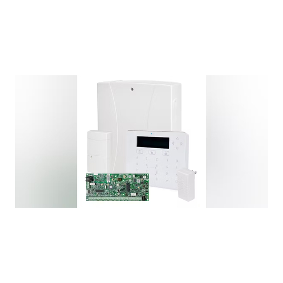
- Page 1 Quick Install Guide 10012516 A...
- Page 2 2GIG Vario Quick Install Guide THIS PAGE INTENTIONALLY LEFT BLANK Copyright © 2016 Nortek Security & Control LLC...
-
Page 3: Table Of Contents
CONTENTS Introduction Select a Mounting Location Install Hardware Main Unit—BUS Connection Connecting BUS Detectors Programming Key Menu Navigation Programming Menu Concept Accessing the Installer Programming Menu Identifying the Connected Devices Zone Attributes Wireless Zones Communication Method Report to Monitoring Station General Settings Keyfobs Exit Programming Mode... -
Page 4: Introduction
Select a Mounting Location Decide where to position the 2GIG Vario system control panel. If possible, choose a central location in order to minimize wiring to expanders and accessories. Before the installation, prepare map out the physical locations of all expanders and accessories. This will determine which types of expanders are required at each location. - Page 5 If connecting remote power supplies, DO NOT connect the red wire (+12V) between the power supply unit and the 2GIG Vario system. For long cable runs, use the correct cable, as listed in "Appendix C: Wiring" in the 2GIG Vario System Installation & Programming Guide. 1. Set BUS Accessory ID Numbers For most devices, a DIP switch number must be set to identify its ID category number.
- Page 6 It is recommended that you use an end-of-line resistor at the far end of each hardwired zone (16 x 2.2K resistors are supplied). In the 2GIG Vario system, you have the ability to separately define the end-of-line resistance of the zones on the main unit and of the wired the wired zones for each eight-unit expander block (Quick Keys ②...
- Page 7 2GIG Vario Quick Install Guide Maximum Current Flows 3. Wire Auxiliary Devices Use the Auxiliary Power AUX (+) COM (–) terminals to power PIRs, glass-break detectors (4-wire types), smoke detectors, audio switches, photoelectric systems and/or any device that requires a 12VDC power supply.
-
Page 8: Connecting Bus Detectors
Connecting BUS Detectors Up to 23 addressable BUS detectors can be assigned to the 2GIG Vario system. BUS detectors can be wired to the main BUS or to a BUS zone expander. For full installation instructions, refer to the instructions supplied with each BUS detector. - Page 9 For maximum operation stability, it is best NOT to exceed a total of 300 meters (1000 feet) of wiring from the BUS zone expander to the 2GIG Vario system panel, and 300 meters (1000 feet) of wiring from the BUS zone expander to the last BUS detector.
-
Page 10: Programming
Programming Menu Concept The 2GIG Vario system programming menu is a dynamic menu that adjusts itself to the system hardwired devices. For example, in order to see a menu option regarding wireless zones or keyfobs, you must first add a wireless expander to the system. -
Page 11: Accessing The Installer Programming Menu
3. Set tamper switches SW1 3, 4 to bypass unused tampers according to the relevant enclosure to prevent tamper alarm. 4. Connect power to the assembled mounted unit. The 2GIG Vario system panel and keypad will initialize for several minutets. 5. Press 6. -
Page 12: Zone Attributes
Zone Attributes The 2GIG Vario system supports up to 50 zones. Each zone can be defined to be a wired zone, a wireless zone, or a BUS zone. The attributes for each zone vary according to the zone's type (wired, wireless, or BUS zone). -
Page 13: Wireless Zones
This noise could be from neighboring devices of another system or from other nearby devices operating on the same frequency. These are "unwanted" signals that the 2GIG Vario system wireless expander must be taught not to listed to. The threshold (set above) is the absolute minimum signal strength needed to be heard from a wireless device in order for the receiver to effectively hear it. -
Page 14: General Settings
General Settings Several system-wide parameters determine how the 2GIG Vario system works. These parameters are set with default values that apply for most installations. If you want to modify the default settings, go through the menus to program any other system parameter settings. -
Page 15: Exit Programming Mode
Operation Test the System Before leaving the site, it is important to fully test the system. The 2GIG Vario system has several testing tools to ensure that the system and its wireless communication features will operate correctly. From the installer menu, select ② (Testing) and compete the following tests: Main Unit noise level, buzzer, speaker, and battery Perform a communication and battery test for each device. -
Page 16: Technical Specifications
2GIG Vario Quick Install Guide Technical Specifications Main Panel Technical Information Input Power AC/DC Adaptor 100–240V 50/60Hz 14.4V—1.5A or 4A PS Current Consumption 60 mA, typical / 70 mA, maximum 1.5A PS: 12 Volts up to 7 Amp-Hours (AH), typical... -
Page 17: Regulatory Information
2GIG Vario Quick Install Guide Regulatory Information FCC Notice This device complies with Part 15 of the FCC's Rules. Operation is subject to the following two conditions: 1. This device may not cause harmful interference, and 2. This device must accept any interference received, including interference that may cause undesired operation. - Page 18 2GIG Vario Quick Install Guide THIS PAGE INTENTIONALLY LEFT BLANK Copyright © 2016 Nortek Security & Control LLC...
Need help?
Do you have a question about the Vario and is the answer not in the manual?
Questions and answers