2gig Technologies Go!Control 2GIG-CNTRL2 Installation & Programming Instructions
Wireless security system
Hide thumbs
Also See for Go!Control 2GIG-CNTRL2:
- Operation and user's manual (52 pages) ,
- User manual (56 pages)

Subscribe to Our Youtube Channel
Related Manuals for 2gig Technologies Go!Control 2GIG-CNTRL2


Summary of Contents for 2gig Technologies Go!Control 2GIG-CNTRL2
- Page 1 Wireless Security System 2GIG-CNTRL2 (2GIG-CP2) Installation & Programming Instructions...
- Page 2 National Fire Protection Association Standard #72 Recommendations for Smoke Detectors STANDARD FOR ALARM LOCATION Smoke detectors used with this system should be installed in accordance with Chapter 2 of the National Fire Alarm Code, ANSI/NFPA 72 (National Fire Protection Association , Batterymarch Park, Quincy, MA 02269) which reads as follows: 2-1.1.1 Smoke alarms shall be installed outside of each separate sleeping area in the immediate vicinity of the bedrooms and on each additional story of the...
-
Page 3: Table Of Contents
Table of Contents Introduction ................2 Programming Navigation ............15 Navigation Arrows & Go To Button ........15 System Overview ............... 3 Questions without Sub-options ..........15 Control Panel Features ............. 4 Questions with Sub-options ..........15 Installation Outline ..............5 Questions with Data to Enter .......... -
Page 4: Introduction
This security system is ETL Listed. For an ETL smoke alarm system, there must be at least one smoke detector programmed into the Control Panel to meet National Fire Protection Association 2GIG-CNTRL2 (NFPA) Rule 72-Chapter 2, and UL 217 requirements. Many (2GIG-CP2) insurance companies require meeting these requirements to qualify for a discount. -
Page 5: System Overview
System Overview The system’s Control Panel features a color touch screen display that The optional GSM radio modem also allows 2-way communications allows control of all system functions and programming. The display with the Alarm.com server. Through this server, subscribers can clearly shows the installer and subscriber system and installation query and control their system using a computer browser from status. -
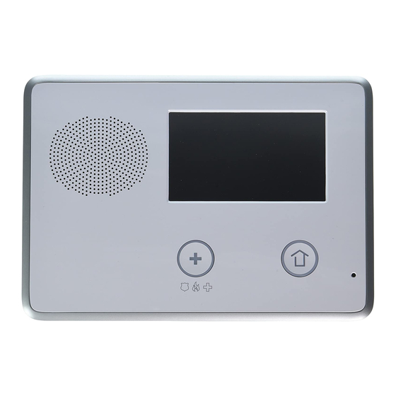
Page 6: Control Panel Features
Control Panel Features ALARM SOUNDER COLOR DISPLAY AND SPEAKER WITH TOUCH SCREEN Sounds all system local alarms, Shows all system information, status, voice prompts, system sounds, and programming, and functions as the audio for 2-way voice communications keypad with the Central Station The display also cycles between clock/calendar and weather (press to manually change) -
Page 7: Installation Outline
Installation Outline Wireless Installation Tips The following outline is intended to guide the installing alarm When installing any wireless system, certain limitations must dealer through the complete installation of a Go!Control system. be considered. Low power wireless transmitter signals will not broadcast equally through all types of construction materials. -
Page 8: Wireless System Sensors
Wireless System Sensors 2GIG-DW10 2GIG-GB1 Thin Door/Window Contact Glass Break Detector • For narrow applications, • Monitors for the sound sensor is only 3/4” wide of breaking glass • Fully supervised • Two test LEDs • Rare earth magnet • Dual shatter recognition •... -
Page 9: System Accessories
System Accessories 2GIG-GSMx 2GIG-BATT1 GSM Module Standard Battery Pack • Cellular telephone module • Standard battery supplied • Plugs into Control Panel with Control Panel • Provides 2-way GSM • Also available as a replacement radio communication item • Enrolls with cellular service provider •... -
Page 10: Installation
Installation Control Panel Mounting Plate IF USING EXTERNAL The Control Panel should be mounted on the wall in an easy GSM ANTENNA, REMOVE MOUNTING KNOCKOUT location for the subscriber to operate the system. PLATE 1. Remove the locking screw from the top of the Control Panel case and MOUNT PLATE remove the mounting plate. -
Page 11: Remote Alarm Sounder
Installation Remote Alarm Sounder The Control Panel provides two terminals for an optional connection THE BELL OUTPUT CAN BE PROGRAMMED FOR SUPERVISION TO DETECT IF THE to a remote electronic alarm sounder (see Figure 10). WIRE TO THE BELL IS CUT ➜... -
Page 12: Optional Gsm Module Installation
Installation Optional GSM Module Installation If using the optional GSM module and one of the GSM antennas. Refer to the following steps: PLUG GSM MODULE INTO 1. Plug the GSM module into the connector on the Control Panel’s circuit CONTROL board. -
Page 13: Control Panel Wiring
Installation Control Panel Wiring The Control Panel includes a “third hand” plastic strap that allows HANG CONSOLE the unit to hang on the mounting plate during installation. ON STRAP PLUG TELEPHONE LINE 1. Hang the Control Panel on the mounting plate using INTO TELEPHONE JACK the “third hand”... -
Page 14: Main Display Screens
Main Display Screens The Control Panel is programmed and operated using the color touch-screen display. The display will show various buttons, indicators, and text to guide the installer and user. Home Screen The Home Screen is the top level screen. It shows the system status with icons to indicate system conditions. -
Page 15: Toolbox Screens
Toolbox Screens The Control Panel is programmed using the “toolbox” screens. Users can access basic programming functions. Installers can access basic and Installer Toolbox functions. Users and installers must enter a valid code to access the programming functions in the toolbox. Other functions do not require entering a code. Toolbox Screens From the Menu Screen, when the TOOLBOX button is pressed, the system will ask for a User Code then display Toolbox Screen one. -
Page 16: System Status Icons
System Status Icons The top line of the Control Panel’s display is the status bar that shows the current system mode, the status of the sensors, and any current system trouble alerts. Special icons are displayed to visually show the system’s current condition. STATUS BAR SHOWING AC POWER IS ON Figure 31. -
Page 17: Programming Navigation
Programming Navigation When the installer is using the System Confi guration menus, the Control Panel will present each programming question sequentially. Most programming questions have a single numeric value response or a simple enabled/disabled selection. Some programming questions have sub-options that can be set. These sub-options are displayed for the question selected and can be accessed through navigation keys on the display. -
Page 18: Programming Outline
Programming Outline Each system installed will require programming. Most installations being performed by the professional alarm installer for a specifi c organization will have common values set in every Control Panel reporting to the same Central Station. Other programming values, such as the account number and sensor setup, will be unique for each installation. -
Page 19: Programming Question Table
Programming Question Table QUESTION DEFAULT QUESTION DEFAULT Select RF sensor # (01-48) Q-28 Select quick exit (0-1) (1) enabled Select RF sensor (#) type (00) unused Q-29 Enter periodic test, in days (0-255) 30 days Varies by RF sensor type Q-31 Enter cancel time, in minutes (5-255) ‡... -
Page 20: System Sensor Types
System Sensor Types Each sensor (wireless or wired) installed in the system is (06) 24-hour Silent Alarm programmed to a specifi c sensor number and sensor type ( zone). This sensor type is active independent of the system arming status. The code for silent panic is sent to the Central Station, but for safety, there are no visual or The sensor number identifi... -
Page 21: System Vocabulary Table
System Vocabulary Table WORD WORD WORD WORD 002 ABORT ENTRY 138 MAIN SKYLIGHT ERROR MAINTENANCE SLIDING ACCESS EXERCISE MASTER SMOKE ALARM EXIT MEDICAL SOUNDER EXIT NOW MEDICINE SOUTH ANNOUNCEMENT EXTERIOR MENU SPACE AREA EXTERNAL MIDDLE SPARE 077 FAILURE MONITOR STAIRS ARMED FAMILY MOTION... -
Page 22: Installer Programming
Installer Programming RF Sensor Programming Refer to Figure 49 for an outline of the steps required to program RF sensors into the Control Panel. The options that can be set for RF Sensor Programming Outline each RF sensor are: The Control Panel can be programmed with up to 48 RF sensors •... -
Page 23: Rf Sensor Summary Screen
Installer Programming RF Sensor Summary Screen RF SENSOR PROGRAMMING (Q-1) OUTLINE After setting all the options for a sensor, the RF sensor summary STEP DOWN SELECT OPTION WITH screen is displayed. The screen can also be displayed for THROUGH OPTIONS THESE KEYS programmed sensors during RF sensor program editing by pressing the SUM button. -
Page 24: Rf Sensor Programming Steps
Installer Programming RF Sensor Programming Steps Select RF sensor (#) equipment code DEFAULT: (0000) other Select RF sensor # (01-48) The equipment code is a 4-digit code that is assigned to the model of sensor Up to 48 wireless RF sensors can be used with each Control Panel. The options being used. - Page 25 Installer Programming Enter RF sensor (#) serial number (7 digits) Construct RF sensor (#) voice descriptor DEFAULT: 0000000 DEFAULT: No default RF sensor serial numbers can be manually entered or learned from the sensor. The voice descriptors are the words the Control Panel will announce for this RF sensor if this sensor is programmed for voice annunciation.
-
Page 26: Wired Sensor Programming
Installer Programming Wired Sensor Programming Wired Sensor Programming Outline The Control Panel can be programmed with up to two wired sensors. The wired sensors are hardwired contact loops connected WIRED SENSOR PROGRAMMING (Q-2) OUTLINE to the loop input terminals on the Control Panel’s terminal strip. ✓... -
Page 27: Wired Sensor Programming Steps
Installer Programming Wired Sensor Programming Steps Select wired sensor (#) normal state DEFAULT: Not used (0) Select wired sensor # (1-2) The two hardwired loops can be wired for normally open (N/O) or normally closed Two hardwired loops can be used as sensors with each Control Panel. The (N/C) contacts, or for end-of-line (EOL) resistor. -
Page 28: Rf Key Fob Programming
Installer Programming RF Key Fob Programming KEY FOB PROGRAMMING (Q-3) OUTLINE STEP DOWN SELECT OPTION WITH RF Key Fob Programming Outline THROUGH OPTIONS THESE KEYS The Control Panel can be programmed with up to eight RF remote control key fobs. ENTER ON KEYPAD OR PRESS Programming the RF key fobs into the Control Panel involves SELECT KEY FOB #... -
Page 29: Rf Key Fob Programming Steps
Installer Programming RF Key Fob Programming Steps Select fob (#) emergency key (0-4) DEFAULT: Disabled (0) Select fob # (1-8) Pressing the buttons on a key fob at the same time for fi ve Up to eight wireless 4-button key fobs can be used with each Control Panel. Key seconds can trigger an emergency alarm. -
Page 30: Rf Keypad Programming
Installer Programming RF Keypad Programming RF Keypad Programming Outline The Control Panel can be programmed with up to four RF remote control keypads or wireless touch screen keypads. Programming RF keypads into the Control Panel involves selecting the sensor number for a particular device, setting or learning the keypad’s serial number, and selecting the other options for the keypad. -
Page 31: Rf Keypad Programming Steps
Installer Programming RF Keypad Programming Steps Enter RF keypad (#) serial number (7 digits) DEFAULT: 0000000 Select RF keypad # (1-4) Up to four wireless keypads can be used with each Control Panel. The options for RF keypad (#) keypad id (read-only) each sensor are programmed with sub-option questions. -
Page 32: Control Panel Programming Questions
Installer Programming Control Panel Programming Questions Q-11 Enter CS #1 phone number (0-25 digits) DEFAULT: No default Enter exit delay, in seconds (45-120) The telephone number for Central Station #1 can be up to 25 digits. DEFAULT: 60 seconds (Required SIA CP-01 Default) •... - Page 33 Installer Programming Q-15 Q-21 Select dialing type (0-1) Select siren supervision time (0-3) DEFAULT: Touch tone (0) DEFAULT: Disabled (0) The digital communicator can dial using tones or pulse. The wiring connection to the external sounder can be supervised. If the wiring to the sounder is cut for 15, 30, or 45 seconds, a bell trouble report can be sent to •...
- Page 34 Installer Programming Q-27 Q-33 Select exit delay restart (0-1) Select cross sensor 47-48 (0-1) DEFAULT: Enabled (1) DEFAULT: Disabled (0) (Required SIA CP-01 Default) When Exit Delay restart is enabled, re-entering the premises through an exit/ The Control Panel can be programmed so sensors 47 and 48 must both be entry door during the Exit Delay will restart the Exit Delay.
- Page 35 Installer Programming Q-37 Q-42 Select fi re bell cutoff (0-4) Select remote control phone (0-3) DEFAULT: 4 minutes (0) DEFAULT: Data and voice (3) When a fi re alarm is triggered, the bell will sound until the fi re bell cutoff time This setting controls remote telephone access to the system.
- Page 36 Installer Programming Q-44 Q-47 Select lock installer programming (0-2) Select trouble resound after holdoff (0-7) DEFAULT: Disabled (0) DEFAULT: Disabled (0) The installer programming lockout feature is provided to prevent takeovers. The Fire and CO sensors are required to re-sound trouble beeps every four hours Control Panel can be set to limit an installer’s access to programming questions until the trouble is resolved, even if the trouble is acknowledged at the Control after a period of 48 hours.
- Page 37 Installer Programming Q-52 Q-58 Select AC loss reports to CS (0-1) Select trouble restore reports to CS (0-1) DEFAULT: Enabled (1) DEFAULT: Enabled (1) AC power loss reports can be sent to the Central Station if the Control Panel Trouble restore reports can be sent to the Central Station when any sensor loses AC power.
- Page 38 Installer Programming Q-64 Q-71 Select smart test reports Select system tamper causes trouble (0-1) DEFAULT: Disabled (0) DEFAULT: Enabled (1) Smart test reports are a way to reduce Central Station traffi c. If smart test reports The Control Panel’s case has a tamper switch that detects if the case has been are enabled and regular periodic test reports are enabled, any non-test report to opened.
- Page 39 Installer Programming Q-76 Q-79 Select force bypass reports (0-1) Select Z-Wave feature (0-3) DEFAULT: Disabled (0) DEFAULT: Disabled but visible (1) The system can report which sensors have been force bypassed by the user The Z-Wave home services feature can be enabled or disabled with various when the system is armed.
- Page 40 Installer Programming Q-84 Q-88 Select services require master code (0-1) Select siren mode (0-1) DEFAULT: Disabled (0) DEFAULT: Sound for burglary and fi re/CO (0) The SERVICES button can be confi gured to require the use of the Master User This setting selects which alarm types will activate a Z-Wave siren linked to the Code to access Services.
-
Page 41: Final Installation Setup
Final Installation Setup Exiting Programming 6. Press BRIGHTNESS / VOLUME. Set the level for the display brightness. Set the chime & voice volume. Press OK when fi nished. After programming the Control Panel, all the changes need to be saved in memory. After saving, the programmed settings will remain in memory, even after a total power loss. -
Page 42: Installer Testing
Installer Testing Testing the System After the installation is complete and the Control Panel programming is complete, the system must be tested to ensure proper operation. System testing is performed through the Installer Toolbox screen. 1. From the Home Screen, press the lower right corner of the screen. 2. -
Page 43: Walk Test Mode
Installer Testing Walk Test Mode Walk Test Mode is for testing all the sensors. It verifi es that each sensor is being received correctly by the Control Panel. The walk test also tests the Control Panel’s indicators and sounder. ✓ NOTE: The Walk Test Mode will automatically end after 25 minutes. -
Page 44: Radio Status Mode
Installer Testing Radio Status Mode ✓ NOTE: GSM Module must be installed to use this function. The GSM Radio Status screen displays data for the GSM radio (if installed). The screen displays signal strength, serial number, registration status, and other information about the GSM radio module status. The information may be helpful for radio installation troubleshooting. -
Page 45: Regulatory Information & Limited Warranty
fi tness, are valid only until the warranty spaced 10 minutes apart to a single number. The FCC Rules expires. This 2gig Technologies Inc. Warranty is in lieu of all and Regulations do not specify the re-attempt period as this can other warranties express or implied. -
Page 46: Reference Programming Question Table
Reference Programming Question Table QUESTION DEFAULT QUESTION DEFAULT Select RF sensor # (01-48) Q-28 Select quick exit (0-1) (1) enabled Select RF sensor (#) type (00) unused Q-29 Enter periodic test, in days (0-255) 30 days Varies by RF sensor type Q-31 Enter cancel time, in minutes (5-255) ‡... -
Page 47: Reference System Vocabulary Table
Reference System Vocabulary Table WORD WORD WORD WORD 002 ABORT ENTRY 138 MAIN SKYLIGHT ERROR MAINTENANCE SLIDING ACCESS EXERCISE MASTER SMOKE ALARM EXIT MEDICAL SOUNDER EXIT NOW MEDICINE SOUTH ANNOUNCEMENT EXTERIOR MENU SPACE AREA EXTERNAL MIDDLE SPARE 077 FAILURE MONITOR STAIRS ARMED FAMILY... -
Page 48: Notes
Notes... - Page 49 Notes...
-
Page 50: Index
Index #’s 2GIG-AC1 replacement power supply 7 Daylight saving end month 36 2GIG-ANT1 internal GSM antenna 7 Daylight saving end Sunday 36 2GIG-ANT1X external in-wall GSM antenna 7 Daylight saving scheme 36 2GIG-ANT2X external attic mount GSM antenna 7 Daylight saving start month 36 2GIG-ANT4X 7 Daylight saving start Sunday 36 2GIG-BATT1 standard battery pack 7... - Page 51 Index Navigation arrows 15 Saving programming 39 NFPA Standard #72 ii Security screen 12 No response sensor type 18 Select keyfob/remote arming mode on system not ready 38 Select siren mode 38 Sensor signal loss through materials 5 Open collector output selection 37 Sensor types 18 Opening reports 35 Sensor zones 18...
- Page 52 Copyright © 2012 v 1.9 233497 E...
Need help?
Do you have a question about the Go!Control 2GIG-CNTRL2 and is the answer not in the manual?
Questions and answers