Moxa Technologies ioLogik E2260 User Manual
Hide thumbs
Also See for ioLogik E2260:
- User manual (144 pages) ,
- Quick installation manual (6 pages) ,
- User manual (106 pages)

Related Manuals for Moxa Technologies ioLogik E2260


Summary of Contents for Moxa Technologies ioLogik E2260
- Page 1 E2260 User’s Manual Fourth Edition, June 2009 www.moxa.com/product © 2009 Moxa Inc. All rights reserved. Reproduction without permission is prohibited.
- Page 2 E2260 User’s Manual The software described in this manual is furnished under a license agreement, and may be used only in accordance with the terms of that agreement. Copyright Notice Copyright © 2009 Moxa Inc. All rights reserved. Reproduction without permission is prohibited.
-
Page 3: Table Of Contents
LED Indicators ......................1-8 Chapter 2. Initial Setup ....................2-1 Hardware Installation ......................2-2 Connecting the Power....................2-2 Grounding the ioLogik E2260 ..................2-2 Connecting to the Network................... 2-2 Setting the RS-485 Baudrate ..................2-2 Adding More I/O Channels ..................2-3 Software Installation......................2-3 Chapter 3. - Page 4 Active Tags Tab......................3-19 SNMP Settings Tab ....................3-20 Server Context Menu....................3-20 Using TFTP to Import/Export Configuration ..............3-22 Using ioEventLog....................... 3-23 Installing ioEventLog ....................3-23 Basic Functions......................3-23 Configuration......................3-24 Checking Connected Devices ..................3-25 Opening Log Files ...................... 3-25 Clearing the Log ......................
- Page 5 Heartbeat Interval ....................... 5-11 Read/Write Privilege ....................5-12 OPC Test Client......................5-12 Appendix A. Liquid Crystal Display Module (LCM) ............. A-1 Appendix B. Modbus/TCP Address Mappings ............B-1 0xxxx Read/Write Coils (Functions 1, 5, 15) ...............B-1 3xxxx Read Only Registers (Function 4) ................B-2 4xxxx Read/Write Registers (Functions 3, 6, 16)..............B-3 Appendix C.
-
Page 6: Chapter 1. Introduction
Introduction Chapter 1. The ioLogik E2260 is a stand-alone Active Ethernet I/O server. It connects RTD sensors and digital output on/off switches for automation applications over Ethernet and IP-based networks. The following topics are covered in this chapter: Overview Traditional Remote I/O Active Ethernet I/O Click&Go... -
Page 7: Overview
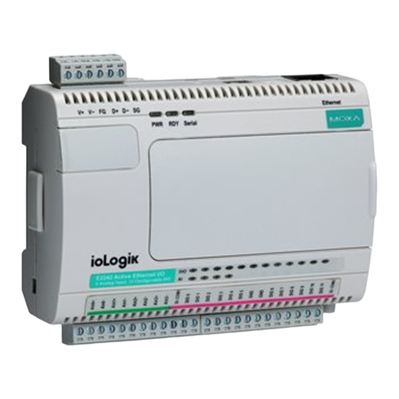
Overview (shown with and without optional LCM) The ioLogik E2260 is part of the E2000 line of ioLogik Active Ethernet I/O servers, which are designed for intelligent, pro-active status reporting of attached sensors, transmitters, transducers, and valves over a network. It includes 2 MB of Flash ROM and 8 MB of SDRAM. An optional hot-pluggable Liquid Crystal Display Module (LCM) can be used to view and configure device settings. -
Page 8: Click&Go
Active Ethernet I/O system. Optional Liquid Crystal Display Module (LCM) In order to make user easy view, the ioLogik E2260 supports an optional hot-pluggable Liquid Crystal Display Module (LCM) for field management and configuration. The LCM can display network and I/O settings such as temperature value. -
Page 9: Product Specifications
E2260 User’s Manual Introduction Product Specifications Ethernet 10/100 Mbps, RJ45 Protection 1.5 KV magnetic isolation Protocols Modbus/TCP, TCP/IP, UDP, DHCP, Bootp, SNMP(MIB for I/O and Network), HTTP Serial Interface RS-485 (2-wire): Data+, Data-, GND Serial Line Protection 15 KV ESD for all signals... - Page 10 E2260 User’s Manual Introduction Virtual RTD Channels Operation Mode Average, Subtraction Digital Output Channels 4, sink type On-state Voltage 24 VDC nominal, 30 VDC max. Output Current Rating Max. 200 mA per channel Optical Isolation 2 KVrms/3 KVDC Protection Over temperature shutdown: 170°C...
-
Page 11: Physical Dimensions
E2260 User’s Manual Introduction Physical Dimensions With LCD Module 5.95 45.63 5.95 Unit = mm 10.7 46.51 93.02 10.98 121.8 44.5 35.1 57.5... -
Page 12: Without Lcd Module
E2260 User’s Manual Introduction Without LCD Module Unit = mm 5.95 24.44 45.39 10.7 46.51 10.98 93.02 121.8 Hardware Reference Panel Guide (TB1) (TB2) NOTE: The reset button restarts the server and resets all settings to factory defaults. Use a pointed object such as a straightened paper clip to hold the reset button down for 15 sec. -
Page 13: Led Indicators
E2260 User’s Manual Introduction LED Indicators Ethernet orange Valid 10 Mbps Ethernet connection Ethernet green Valid 100 Mbps Ethernet connection (flashing) Transmitting or receiving data System Power is on Power is off System error green (steady) Unit is functioning normally green (flashing) Click&Go ruleset is active... -
Page 14: Chapter 2. Initial Setup
Initial Setup Chapter 2. This chapter describes how to install the ioLogik E2260. The following topics are covered: Hardware Installation Connecting the Power Grounding the ioLogik E2260 Connecting to the Network Setting the RS-485 Baudrate Adding More I/O Channels Software Installation... -
Page 15: Hardware Installation
Hardware Installation Connecting the Power Connect the 12 to 48 VDC power line to the ioLogik E2260’s terminal block (TB1). If power is properly supplied, the Power LED will glow a solid red color until the system is ready ATTENTION Disconnect the power before installing and wiring Disconnect the power cord before installing and/or wiring your ioLogik E2260. -
Page 16: Adding More I/O Channels
Windows utility provided for the configuration and management of the ioLogik E2260 and attached I/O devices. It may be used from anywhere on the network to monitor and configure the ioLogik E2260. You may also configure some of the settings through the web console or optional LCM. - Page 17 E2260 User’s Manual Initial Setup If ioAdmin is unable to find the ioLogik E2260, there may be a problem with your network settings. When multiple ioLogik E2000 units are on the same network, remember that each unit has the same default IP address. You will need to assign a different IP address to each unit to avoid IP conflicts.
-
Page 18: Chapter 3. Utilities
Utilities Chapter 3. This chapter goes over the functions available in ioAdmin, the ioLogik E2260’s main configuration and management utility. The following topics are covered: Introduction to ioAdmin Features of ioAdmin ioAdmin Main Screen Main Screen Overview Wiring Guide Menu Items... -
Page 19: Introduction To Ioadmin
Windows utility provided with your ioLogik E2260. ioAdmin’s graphical user interface gives you easy access to all status information and settings. The ioLogik E2260 also supports configuration by web console and by optional LCM, but full configuration and management is only available through ioAdmin. - Page 20 E2260 User’s Manual Utilities Configuration File ioAdmin allows the entire configuration of the ioLogik E2260 to be saved as a file. The file is viewable as text and can serve three purposes: as a record or backup of configuration...
-
Page 21: Ioadmin Main Screen
This is ioAdmin’s main screen. The main window defaults to the I/O Configuration tab, which displays a figure of the ioLogik E2260 and the status of every I/O channel below it. The other tabs in the main window take you to server and network settings, and further functions are available when you log on as an administrator. -
Page 22: Wiring Guide
Utilities Wiring Guide ioAdmin provides a wiring guide to the ioLogik E2260. You may access the wiring guide by right-clicking the figure of the ioLogik E2260 in the I/O Configuration tab. Select “Wiring Guide” in the submenu to open a help file showing the wiring information and electrical characteristics of the ioLogik E2260. -
Page 23: System
E2260 User’s Manual Utilities When importing a server list, you will be prompted to select which servers on the list need to be imported. The file will have a .SLT extension and can be opened as a text file. The server list will provide the following information for each server: 1. -
Page 24: Sort
E2260 User’s Manual Utilities Sort The Sort menu allows the server list in the navigation panel to be sorted by connection, type, and location. Help In the Help menu, you can view wiring guides and information about ioAdmin. Quick Links Quick links are provided to search for I/O servers on the network and sort the server list. -
Page 25: Main Window
E2260 User’s Manual Utilities Main Window I/O Configuration Tab (General) The I/O Configuration tab shows the status of every I/O channel. This is the default tab when you first open ioAdmin. Server Info Tab Server information, such as firmware revision, is displayed in the Server Info tab. -
Page 26: Server Settings Tab (General)
The Message Monitor tab will display any TCP/UDP I/O messages received from the ioLogik E2260. When you install the ioLogik E2260 for the first time, the Click&Go ruleset will not have been defined yet, so no messages will be displayed. Please refer to Chapter 5 for information on using Click&Go. -
Page 27: Ioadmin Administrator Functions
When making configuration changes, you will need to click Update or Apply to save the changes. Some changes will require a restart of the ioLogik E2260 in order to take effect, and you will be given the option to restart the computer if necessary. - Page 28 Accurate readings beyond these ranges cannot be guaranteed. Virtual Channels The ioLogik E2260 provides virtual channels so you can easily determine the average or deviation values for any attached temperature sensor. A virtual channel can operate in Average Mode or Deviation Mode.
- Page 29 Power On Settings Use this field to set the initial behavior of the DO channel when the ioLogik E2260 is powered on. You may configure whether or not the DO is set to OFF or ON at power up. For DO channels in Output Pulse mode, you may configure whether or not the pulse output commences at power up.
-
Page 30: Server Settings Tab (Administrator)
E2260 User’s Manual Utilities Test DO You may test the DO channel by using ioAdmin. DO-DO: set the DO to “ON” or “OFF” DO-Pulse: activate or stop pulse generation. Server Settings Tab (Administrator) You may set the password, server name, location, date, time, time zone, and time server in the Server Settings tab. - Page 31 E2260 User’s Manual Utilities You may set up the Daylight Saving schedule by clicking the “Daylight Saving” button. You may choose EU type, US type, or User defined type. User defined type allows you to define the days and offset hours.
-
Page 32: Network Tab
“System Log” field. The default port number is 4040. For additional information, please refer to the ioEventLog section later in this chapter. Network Tab The Network tab is where you configure IP settings, Modbus/TCP Alive Check Timeout settings, DNS settings, Serial settings, and Web Access settings for the ioLogik E2260. 3-15... - Page 33 E2260 User’s Manual Utilities IP Settings: You can assign a static or dynamic IP address to the ioLogik E2260, as well as the subnet mask and gateway address. The Accessible IP screen can be used to control network access to the ioLogik E2260 and attached sensors.
-
Page 34: Firmware Update Tab
Utilities Firmware Update Tab The ioLogik E2260 supports remote firmware updates through the Firmware Update tab. Enter the path to the firmware file or click on the icon to browse for the file. Click Update to update the firmware. The wizard will lead you through the process until the server is restarted. -
Page 35: Click&Go Logic Tab
I/O data. Please refer to Chapter 5 for more information. Changes made in the Click&Go Logic tab are not effective until the ioLogik E2260 is restarted, just like changes made in other tabs. Note that when an I/O channel is used in Click&Go Logic, its range and units become fixed and cannot be modified. -
Page 36: Active Tags Tab
E2260 User’s Manual Utilities Active Tags Tab When logged in as an administrator, fill in the IP address in the Active Tags tab to configure Active OPC Address and Port settings. ioLogik Active Ethernet I/O can support up to 5 IPs at the same time. -
Page 37: Snmp Settings Tab
E2260 User’s Manual Utilities SNMP Settings Tab The ioLogik Ethernet I/O supports SNMP V1, V2c, and V3 (Simple Network Management Protocol) to monitor network and I/O devices with SNMP Network Management software. It is useful in building automation and telecom applications. Use these fields to enable SNMP and set the read and write community strings for SNMP V1 and V2c, or use authentication for SNMP V3. - Page 38 E2260 User’s Manual Utilities Disconnect Select this command to have ioAdmin drop the network connection with the selected ioLogik server. Delete I/O Server Select this command to have ioAdmin remove the selected server. Add Serial I/O Server Select this command to manually add a serial I/O server by using its Unit ID.
-
Page 39: Using Tftp To Import/Export Configuration
The ioLogik E2260 supports the use of TFTP to import or export configuration files. The following is an example using Windows TFTP and an ioLogik E2260 with an IP address of 192.168.127.254: 1. Enter “TFTP 192.168.127.254 GET ik2260.txt” to get the ioLogik’s configuration file. -
Page 40: Using Ioeventlog
Windows utility provided for the monitoring of the ioLogik E2260 and attached I/O devices. It may be used from anywhere on the network to monitor the ioLogik E2260. Installation from CD: Insert the Document and Software CD into the host computer. Run SETUP.EXE, which is located in the root directory. -
Page 41: Configuration
E2260 User’s Manual Utilities Source model Configuration In the System menu, select Settings to configure ioEventLog. The Alarm Listen Port is the TCP port number that will be monitored for status events. You can modify this setting as necessary to receive signals through a firewall. It will need to match the settings for the ioLogik server that is being monitored. -
Page 42: Checking Connected Devices
E2260 User’s Manual Utilities You can also select the color of each event type in the log. Checking Connected Devices You can see which I/O servers are already connected to ioEventLog by selecting Connected Device List from the Connection menu. You will be prompted to view which devices are connected. -
Page 43: Clearing The Log
E2260 User’s Manual Utilities Clearing the Log If you wish to clear the log, you can select Clear from Log menu. This will clear all events for the current day. The cleared events will not be saved in that day’s logs. After the logs are cleared, new events will be displayed and recorded as usual. -
Page 44: Chapter 4. Using The Web Console
Using the Web Console Chapter 4. You may use the ioLogik E2260’s built in web console to configure many options. The following topics are covered: Introduction to the Web Console Basic Settings Network Settings General Settings Ethernet Configuration RS-485 Settings... -
Page 45: Introduction To The Web Console
E2260 without saving your configuration, the ioLogik E2260 will discard all submitted changes. Basic Settings On the Basic Settings page, you may set the ioLogik E2260’s system time or provide the IP address of a time server for time synchronization. -
Page 46: Network Settings
When enabled, the Host Connection Watchdog activates Safe Status settings for DO channels when the ioLogik E2260 loses its network connection for the specified amount of time. By default, the Watchdog is disabled. You may use ioAdmin to configure each DO channel's Safe Status setting. -
Page 47: Rs-485 Settings
On the RS-485 Settings page, you may view the serial communication parameters, but no configuration changes are allowed. The baudrate may only be configured by the physical dial on the back of the ioLogik E2260. This is a reserved function. I/O Settings... -
Page 48: Do Channels
E2260 User’s Manual Using the Web Console The following table is a list of supported sensor types and ranges. Sensor Type Degree Count PT50, 0.00385 -200 to 850°C -2000 to 8500 PT100, 0.00385 -200 to 850°C -2000 to 8500 PT200, 0.00385... -
Page 49: System Management
E2260 User’s Manual Using the Web Console You may use the Power On Setting field to specify the channel's status when the ioLogik E2260 is powered on, and the Safe Status Setting field to specify the channel’s status if the network is disconnected. -
Page 50: Snmp Agent
E2260 User’s Manual Using the Web Console Refer to the following table for additional configuration examples. Allowed Hosts IP address/Netmask Any host Disable 192.168.1.120 192.168.1.120 / 255.255.255.255 192.168.1.1 to 192.168.1.254 192.168.1.0 / 255.255.255.0 192.168.0.1 to 192.168.255.254 192.168.0.0 / 255.255.0.0 192.168.1.1 to 192.168.1.126... -
Page 51: Firmware Update
E2260 User’s Manual Using the Web Console Firmware Update On the Firmware Update page, you may load new or updated firmware onto the ioLogik. Import System Config On the Import System Config page, you may import a configuration onto the ioLogik server. The configuration file must have been generated by ioAdmin or through the web console. -
Page 52: Lcm
Confirm password fields blank. ATTENTION If you forget the password, the ONLY way to configure the ioLogik E2260 is by using the reset button to load the factory defaults. Before you set a password for the first time, it is a good idea to complete the ioLogik’s configuration and export the configuration to a file. -
Page 53: Chapter 5. Active Opc Server Lite
Active OPC Server Lite Chapter 5. In this chapter, we explain how to use ioAdmin to configure your ioLogik product. The following topics are covered in this chapter: Overview Introduction to Active OPC Server Lite Active OPC Server Lite – From Pull to Push Features of Active OPC Server Lite Active OPC Server Lite Specifications Installation of Active OPC Server Lite... -
Page 54: Overview
E2260 User’s Manual Active OPC Server Lite Overview OPC (originally OLE for process control) is an industry standard created with the collaboration of a number of leading worldwide automation hardware and software suppliers, working in cooperation with Microsoft. The standard defines methods for exchanging real-time automation data between PC-based clients using Microsoft operating systems. -
Page 55: Active Opc Server Lite - From Pull To Push
E2260 User’s Manual Active OPC Server Lite Active OPC Server Lite – From Pull to Push When first looking up the I/O divices’ Modbus table, users need to create one tag within 19 or more steps including specifying the IP address, selection of the protocols, and define the data type. -
Page 56: Features Of Active Opc Server Lite
E2260 User’s Manual Active OPC Server Lite The “push” technology also includes the update for the tags. When the I/O the status changes, there will be updates from the ioLogik to Active OPC Server Lite. Compared to constantly polling (pull-based) the status, this feature efficiently reduces the network bandwidth usage and speeds up the response time with event-driven, push-based status updates. -
Page 57: Active Opc Server Lite Specifications
E2260 User’s Manual Active OPC Server Lite Dynamic IP Address Support Active OPC Server also delivers the flexibility of using dynamic IP addresses on the ioLogik. As for the traditional data acquisition application, I/O devices are not capable of using this approach. -
Page 58: Active Opc Server Lite
E2260 User’s Manual Active OPC Server Lite Active OPC Server Lite Main Screen Overview Active OPC Server Lite’s main screen displays a figure of the mapped ioLogik with the status of every I/O tag. Note that configuration and tags are not available until you have the ioLogik to create the tags. -
Page 59: Menu Items
E2260 User’s Manual Active OPC Server Lite Menu Items File From the File menu, you can export the list of the ioLogik that are currently displayed in the navigation panel. You also can import a list into Active OPC Server Lite. -
Page 60: Sort
E2260 User’s Manual Active OPC Server Lite Register OPC Server is used to register the DCOM components to the Windows system. After Active OPC Server Lite is installed, it will automatically configure the DCOM. Unregister OPC Server is used to cancel the registration of the DCOM components from the Windows system. -
Page 61: Tag Generation
E2260 User’s Manual Active OPC Server Lite Tag Generation Push Tag Configuration from ioAdmin Tag configuration of an ioLogik is specified by ioAdmin configuration utility. Start the ioAdmin, log in as an administrator and go to the Active Tags. - Page 62 E2260 User’s Manual Active OPC Server Lite 2. Click Yes to restart the ioLogik. 3. Specify the channels needed to be monitored by Active OPC Server Lite. 4. Click on the Create Tags button to push the tag configuration to Active OPC Server Lite.
-
Page 63: Advanced Settings
E2260 User’s Manual Active OPC Server Lite Advanced Settings Advanced settings of the tags define the period that an ioLogik checks for the counter input status. By default, the status is checked as soon as it changes. Users can define the interval starting from 100 ms to 60 seconds. -
Page 64: Read/Write Privilege
E2260 User’s Manual Active OPC Server Lite Read/Write Privilege An input channel can only be read while an output channel is read/write acceptable showing on the Active OPC Server Lite. Note that if an output channel has been used in the Click&Go logic, the tags for that channel are read-only. - Page 65 E2260 User’s Manual Active OPC Server Lite Click on the Group Add and specify the Group Name (user-defined). A blank tag monitoring screen will start. Click Item Browse and select the channel needed to be monitored. 5-13...
- Page 66 E2260 User’s Manual Active OPC Server Lite To write to the output channel, specify an output channel first. Then, select Item Write from the menu bar. 5-14...
-
Page 67: Appendix A. Liquid Crystal Display Module (Lcm
The LCM is hot-pluggable and can be used to configure the network settings or display other settings. When plugged in, the LCM displays the ioLogik E2260 “home page,” and pressing any button takes you into the settings and configuration. - Page 68 E2260 User’s Manual Liquid Crystal Display Module (LCM) Display Explanation / Actions Enter this submenu to display information and settings for the network: ethernet link MAC address IP mode <ioLogik E2260> network IP address netmask gateway DNS server-1 DNS server-2 Enter this submenu to display information about the ruleset being used by the active I/O system.
-
Page 69: Appendix B. Modbus/Tcp Address Mappings
Modbus/TCP Address Mappings Appendix B. 0xxxx Read/Write Coils (Functions 1, 5, 15) Reference Address Data Type Description 00001 0x0000 1bit CH0 RTD Reset Minimum Value <R> Always 0 <W> 1=Reset to current value, 0=return illegal data value 00002 0x0001 1 bit CH1 RTD Reset Minimum Value 00003 0x0002... -
Page 70: 3Xxxx Read Only Registers (Function 4
E2260 User’s Manual Modbus/TCP Address Mappings Reference Address Data Type Description 00032 0x001F 1 bit CH1 DO Status 00033 0x0020 1 bit CH2 DO Status 00034 0x0021 1 bit CH3 DO Status 00035 0x0022 1 bit CH0 DO Power-On Status <RW>... -
Page 71: 4Xxxx Read/Write Registers (Functions 3, 6, 16
E2260 User’s Manual Modbus/TCP Address Mappings Reference Address Data Type Description 30014 0x000D 1 word CH1 RTD Minimum Value 30015 0x000E 1 word CH2 RTD Minimum Value 30016 0x000F 1 word CH3 RTD Minimum Value 30017 0x0010 1 word... - Page 72 E2260 User’s Manual Modbus/TCP Address Mappings Reference Address Data Type Description 40017 0x0010 1 word CH0 DO Pulse Output High Signal Width – Hi Word <RW> 0~4294967295 40018 0x0011 1 word CH0 DO Pulse Output High Signal Width – Lo Word <RW>...
- Page 73 E2260 User’s Manual Modbus/TCP Address Mappings Reference Address Data Type Description 40043 0x002A 1 word CH2 RTD Sensor Type 40044 0x002B 1 word CH3 RTD Sensor Type 40045 0x002C 1 word CH4 RTD Sensor Type 40046 0x002D 1 word...
- Page 74 E2260 User’s Manual Modbus/TCP Address Mappings Reference Address Data Type Description 40084 0x0053 1 word CH3 DO Status 40085 0x0054 1 word CH0 DO Safe Status <RW> 0=OFF, 1=ON 40086 0x0055 1 word CH1 DO Status 40087 0x0056 1 word...
- Page 75 E2260 User’s Manual Modbus/TCP Address Mappings Reference Address Data Type Description 40355 0x0162 1 word Internal Register 18 Value 40356 0x0163 1 word Internal Register 19 Value 40357 0x0164 1 word Internal Register 20 Value 40358 0x0165 1 word...
-
Page 76: Appendix C. Used Network Port Numbers
Used Network Port Numbers Appendix C. E2260 Network Port Usage Port Type Usage BOOTPC DHCP Export/Import File Web Server SNMP Modbus Communication 4040 ioEventLog 4800 Auto Search 9000 Active Message (Default) 9000 Active Message (Default) 9020 Peer-to-Peer Function 9900 Active Tags updates (default) -
Page 77: Appendix D. Snmp Mib Ii
SNMP MIB II Appendix D. RFC1213 MIB II Supported SNMP Variables The following SNMP variables are built into the ioLogik firmware and are compliant with RFC1213 MIB II. System MIB SysContact SysDescr SysLocation SysName SysObjectID SysServices SysUpTime Interfaces MIB ifAdminStatus ifOutErrors ifDescr ifOutNUcastPkts... - Page 78 E2260 User’s Manual SNMP Agents with MIB II IP MIB ipAdEntAddr ipInHdrErrors ipRouteAge ipAdEntBcastAddr ipInreceives ipRouteDest ipAdEntIfIndex ipInUnknownProtos ipRouteIfIndex ipAdEntNetMask IpNetToMediaIfIndex ipRouteInfo ipAdEntReasmMaxSize IpNetToMediaNetAddress ipRouteMask ipDefaultTTL IpNetToMediaPhysAddress ipRouteMetric1 ipForwarding IpNetToMediaType ipRouteMetric2 ipForwDatagrams ipOutDiscards ipRouteMetric3 ipFragCreates ipOutNoRoutes ipRouteMetric4 ipFragFails ipOutRequests...
- Page 79 E2260 User’s Manual SNMP Agents with MIB II Address Translation MIB AtIfIndex AtNetAddress AtNetAddress AtPhysAddress TCP MIB tcpActiveOpens tcpCurrEstab tcpPassiveOpens tcpAttempFails tcpEstabResets tcpRetransSegs tcpConnLocalAddress tcpInErrs tcpRtoAlgorithm tcpConnLocalPort tcpInSegs tcpRtoMax tcpConnRemAddress tcpMaxConn tcpRtoMin tcpConnRemPort tcpOutRsts tcpConnState tcpOutSegs SNMP MIB snmpEnableAuthenTraps...
-
Page 80: Private Mib File And Snmp Variables
E2260 User’s Manual SNMP Agents with MIB II Private MIB File and SNMP Variables Moxa also provides an SNMP to I/O MIB file that can help you monitor I/O status with SNMP software. You can find the MIB file on the Document and Software CD. - Page 81 CGI Commands Appendix E. Using a web browser or standard HTTP protocol will make it easier for a Security SCADA system to monitor and control an ioLogik via CGI commands. Syntax to get the settings is as follows. Starting with the ioLogik’s IP or URL, specify getParam.cgi with a question mark.
- Page 82 E2260 User’s Manual CGI Commands 6:JPt200, 7:JPt500, 8:JPt1000, 9 :Ni 100, 10 :Ni 200, 11 :Ni 6:JPt200, 7:JPt500, 8:JPt1000, 9 :Ni 100, 10 :Ni 200, 11 :Ni 500, 12 :Ni 1000, 13 :Ni 120, 14 :Resistance (1-310 mΩ), 500, 12 :Ni 1000, 13 :Ni 120, 14 :Resistance (1-310 mΩ), 15:Resistance (1-620 mΩ), 16 :Resistance (1-1250 mΩ),...
- Page 83 E2260 User’s Manual CGI Commands Syntax to get the settings is as follows. Starting with the ioLogik’s IP or URL, specify setParam.cgi with a question mark. Then specify the command with another question mark as the ending. Those commands are case sensitive and the & sign is used to combine multiple commands.
- Page 84 E2260 User’s Manual CGI Commands Commands to set DO channels Commands to set DO Channels DOMode_00 DOMode_01 (0:DO, 1:PULSE OUTPUT) (0:DO, 1:PULSE OUTPUT) DOStatus_00 DOStatus_01 (0:OFF, 1:ON) (0:OFF, 1:ON) DOLowWidth_00 DOLowWidth_01 DOHighWidth_00 DOHighWidth_01 DOPulseStart_00 DOPulseStart_01 (0:STOP, 1:START) (0:STOP, 1:START)
-
Page 85: Appendix F. Factory Default Settings
Factory Default Settings Appendix F. The ioLogik E2260 is configured with the following factory defaults: Default IP Address: 192.168.127.254 Default Netmask: 255.255.255.0 Default Gateway: 0.0.0.0 Communication Watchdog: Disable RTD Mode: PT 100 Unit: Degree C DO Mode: DO Safe Status: Power On Status: 1 ×... -
Page 86: Appendix G. Pinouts And Cable Wiring
Pinouts and Cable Wiring Appendix G. Ethernet Port Pinouts Signal Serial Port Pinouts E2260 RS-485 Network Adapter Pin Assignment RTD Input Wiring Structure... -
Page 87: 2-Wire
E2260 User’s Manual Pinouts and Cable Wiring 2-wire 3-wire Digital Output Structure... -
Page 88: Output Channel
E2260 User’s Manual Pinouts and Cable Wiring Output Channel * DO PWR is for powering up the field Power LED. Terminal Block Pin Assignments (TB1) (TB2) (Power Input) (RS-485) V+ (12-48V) Data+ Data- 10 11 12 13 14 15 16 17 18 19 20 21 22 23 24... -
Page 89: Appendix H. Accuracy
0.15% of FSR. Verification with Precision Resistor A resistor with Ohm input could be used for verification. Suppose that you use the ioLogik E2260, which is rated at 100 Ω 1%, and select 1-310 Ω mode. The measured temperature would fall within 100±(100 ×...
Need help?
Do you have a question about the ioLogik E2260 and is the answer not in the manual?
Questions and answers