
Related Manuals for Partlow MIC 8200


Summary of Contents for Partlow MIC 8200
- Page 1 MIC 8200 Form 3032 Edition 4 ©July 1993 Updated Jan. 1994 Installation, Wiring, Operation Manua Brand...
- Page 2 nformation in this installation, wiring, and operation manual is subject to change without notice. One manual is provided with each instrument at the time of shipment. Extra copies are available at the price published on the front cover. Copyright © July 1993, all rights reserved. No part of this publication may be reproduced, transmitted, transcribed or stored in aretrieval system, or translated into any language in any form by any means without the written permission...
-
Page 3: Table Of Contents
Table of Contents SECTION 1 - GENERAL Page Number 1.1 Product Description SECTION 2 - INSTALLATION & WIRING 2.1 Installation and Wiring 2.2 Input Connections 2.3 Output Connections SECTION 3 - CONFIGURATION & OPERATION 3.1 Configuration and Operation 3.2 Operation Summary 3.3 Configuration Summary 3.4 Auto Tune Method 3.5 Manual Tuning Method... - Page 4 FIGURES & TABLES Figure 1-1 Controller Display Illustration Figure 2-1 Panel Opening Sizes and Installation Figure 2-2 Noise Suppression Figure 2-3 Noise Suppression Figure 2-4 Wiring Label Figure 2-5 AC Power Figure 2-6 Thermocouple Input Figure 2-7 RTD Input Figure 2-8 Volt, mV, mADC Input Figure 2-9 24 Volt Transmitter Power Supply...
-
Page 5: Section 1 - General
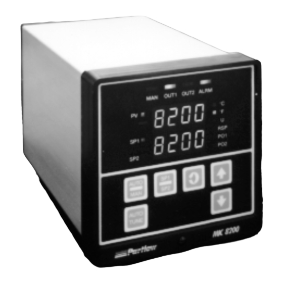
Product Description 1.1 1.1.1 GENERAL This instrument is a microprocessor based single loop controller capable of measuring, displaying and controlling temperature, pressure, flow, and level from a variety of inputs. Most heating outputs are easily tuned using the instrument’s Auto Tune function with several choices for control algorithms and control responses. - Page 6 1.1.3 CONTROL The instrument can be programmed for on-off, time proportioning, current proportioning, or position proportioning control implementations depending on the output(s) specified for the instrument in the model number. The Auto Tune function can be used for a heating output assigned to output 1 at the Setpoint 1 value.
-
Page 7: Installation And Wiring 2.1
Installation and Wiring 2.1 Prior to proceeding with installation, verify the AC power input required by the instrument. AC power input is either 115 VAC or 230 VAC and is specified in the model number and on the wiring label affixed to the instrument housing. See Figure 2-4 (page 12) for a wiring label description. -
Page 8: Input Connections
Preparation for Wiring 2.2 2.2.1 WIRING GUIDELINES Electrical noise is a phenomenon typical of industrial environments. The following are guidelines that must be followed to minimize the effect of noise upon any instrumentation. 2.2.1.1 INSTALLATION CONSIDERATIONS Listed below are some of the common sources of electrical noise in the industrial environ- ment: •... -
Page 9: Noise Suppression
In applications where a High Voltage Transformer is used, (i.e. ignition systems) the second- ary of the transformer should be isolated from all other cables. This instrument has been designed to operate in noisy environments, however, in some cases even with proper wiring it may be necessary to suppress the noise at its source. 2.2.1.4 USE OF SHIELDED CABLE Shielded cable helps eliminate electrical noise being induced on the wires. - Page 10 FIGURE 2-3 Inductive Load 2.2.2 SENSOR PLACEMENT (Thermocouple or RTD) Two wire RTD's should be used only with lead lengths less then 10 feet. If the temperature probe is to be subjected to corrosive or abrasive conditions, it should be protected by the appropriate thermowell.
- Page 11 TABLE 2 Temperature Error in °F per 1000 feet of Leadwire Thermocouple Type: 1.54 1.84 1.91 1.04 12.60 2.65 2.27 2.41 1.09 2.97 2.96 1.64 19.80 4.21 3.66 1.57 3.86 1.75 4.81 4.76 2.63 31.50 6.69 5.74 2.47 6.09 2.77 7.47 7.52 4.14...
-
Page 12: Wiring Label
(Continued from page 11) Example: An application uses 2000 feet of 18 AWG copper lead wire for a 3 wire RTD sensor. What is the worst case error due to this leadwire length? Terr = TLe * L TLe = +/-.46 (°F/1000 ft) from Table 3 Terr = +/-.46 (°F/1000 ft) * 2000 ft Terr = +/- 0.92°F FIGURE 2-4 WIRING LABEL... -
Page 13: Output Connections
Input Connections 2.3 In general, all wiring connections are made to the instrument after it is installed. Avoid electrical shock. AC power wiring must not be connected to the source distribution panel until all wiring connection procedures are completed. 2.3.1 INPUT CONNECTIONS FIGURE 2-5 AC Power Connect 115 VAC hot and neutral to terminals B and A respectively as illustrated below. -
Page 14: Rtd Input
FIGURE 2-7 RTD Input Make RTD connections as illustrated below. For a three wire RTD, connect the resistive leg of the RTD to terminal 3, and the common legs to terminal 1 and 5. For a two wire RTD, connect one wire to terminal 1 and the other wire to terminal 3 as shown below. A jumper wire supplied by the customer must be installed between terminals 1 and 5. -
Page 15: Volt Transmitter Power Supply
VOLT DC INPUT MILLIVOLT DC INPUT Rear View Rear View Shielded Twisted Shielded Twisted Pair Pair MILLIVOLT DC SOURCE 50 MILLIVOLT DC VOLT DC MAXIMUM SOURCE 5 VOLT DC MAXIMUM FIGURE 2-9A 24 Volt Transmitter Power Supply (XP Option) Make connections as shown below. Terminal 3 is positive (+) and terminal 1 is negative (-). Be sure the input conditioning jumpers are properly positioned for the input type selected. -
Page 16: Remote Setpoint Input
FIGURE 2-10 Remote Setpoint Input - VDC and mADC and Potentiometer Input connections are illustrated below. Terminal 8 is positive and terminal 5 is negative. The remote setpoint input can be configured for either 0 to 5VDC or 1 to 5 VDC input. Make sure that the voltage input matches the voltage configuration selected in the Program mode. -
Page 17: Remote Setpoint Selection
FIGURE 2-11 Remote Setpoint Selection of one of two preset setpoint values (Optional) A programmable feature allows for the setpoint value to be toggled between two preselected values when a dry contact closure is sensed between terminals 8 and 5. For more information see section 3 (page 21). - Page 18 FIGURE 2-13 Alternate Remote Digital Communications RS 485 Terminals G & H (Optional) If the communications network continues on to other units, connect the shields together, but not to the instrument. A terminating resistor should be installed at the terminals of the last instrument in the loop.
-
Page 19: Ssr Driver Output
RELAY C Rear View LOAD INPUT POWER GROUND FIGURE 2-15 SSR Driver Output Connections are made to the solid state relay driver output located in the Relay A position as shown. The solid state relay driver is a 5 VDC current sink output type. Connect the solid state relay driver(s) in the Relay B and C position (if present) in the same manner. -
Page 20: Madc Output
FIGURE 2-16 mADC Output Connections are made for current outputs 1 or 2 as shown below. Connect the positive lead to terminal 6 for Output 1 or terminal 7 for Output 2 , the negative leads connect to terminal 5. Current outputs will operate up to 650 ohms maximum load. -
Page 21: Configuration And Operation 3.1
Configuration and Operation 3.1 3.1.1 POWER UP PROCEDURE Verify all electrical connections have been properly made before applying power to the instrument. If the instrument is being configured (set up) for the first time, it may be desirable to discon- nect the controller output connections. -
Page 22: Operation Summary 3.2
Operation Summary 3.2 3.2.1 KEYPAD OPERATION AUTO/MANUAL KEY This key is used to enter the Manual mode (Standby) of operation from the Control mode and visa versa. AUTO TUNE KEY This key is used to initiate the Auto Tuning of the Output 1 proportional output for heating applications. -
Page 23: Configuration Summary 3.3
3.2.2 CONFIGURATION DISPLAYS During configuration, the upper display shows the parameter codes. The lower digital display shows the parameter value. During operation, the upper display is used to indicate process value or deviation from setpoint. The lower display can be used to indicate setpoint value or proportional output percentage. -
Page 24: Enable Mode Configuration Procedures
3.3.3 TUNE MODE CONFIGURATION The Tune mode is used to adjust the tuning parameters and the alarm setting needed for operation of the instrument. If Auto Tuning is used to determine the parameters for the heating output (Output 1), those parameters in the Tune mode (except Cycle time) need not be configured. - Page 25 ENABLE MODE FLOW CHART Press UP and DOWN EnAb ARROWS for 10 seconds to enter this loop. EtSt ECAL EPro Etun ESbY ESPS Actual Display ESPC On/Off Display - Use arrow keys to turn on or off EAtn Scroll Key Numeric Display - Use arrow keys to change value...
- Page 26 PROGRAM MODE FLOW CHART Prog rLyA inPS rLyb iCor out1 rLyC o1uL diSP dPoS o1LL out2 o2uL HyCo o2LL Actual Display HyAo out3 On/Off Display - Use arrow keys to turn on or off Scroll Key Numeric Display - Use arrow keys to change value Up Arrow Key Down Arrow...
- Page 27 Prnd rSPu Colr rSPL Co2r SPuL Pout SPLL AtFr P1EC P2EC SPrr FSCn...
- Page 28 Com (Optional) CCon AduL AdLL ASuL ASLL Actual Display On/Off Display - Use arrow keys to turn on or off Scroll Key Numeric Display - Use arrow keys to change value Up Arrow Key Down Arrow...
-
Page 29: Program Mode Configuration Procedures
TABLE 3-2 PROGRAM MODE CONFIGURATION PROCEDURE Press and release the SCROLL key until Prog is displayed. Use the DOWN key to enter the Program mode. Depress and release the SCROLL key to advance the display through the parameters and their values. The upper display will show the parameter codes. The lower display will show the parameter value selected. - Page 30 STEP DESCRIPION DISPLAY AVAILABLE FACTORY YOUR CODE SETTINGS SETTING SETTING Output 2 out2 0 = None or Position Proportioning Direct -Close 1 = On-Off Direct (Cooling) 2 = On-Off Reverse (Heating) 3 = Time Proportioning- Direct (Cooling) 4 = Time Proportioning-Reverse (Heating) 5 = Current Proportioning- Direct (Cooling)
- Page 31 STEP DESCRIPION DISPLAY AVAILABLE FACTORY YOUR CODE SETTINGS SETTING SETTING Engineering units -9999 to 9999 Lower Value Hysteresis for HyCo 0 to 300°/Units On/Off Control (width of hysteresis band) Output(s) 0 to 300 °/Units Hysteresis for HyAo Alarm Output (width of hysteresis band) Setpoint 0 to 4 Configuration...
- Page 32 STEP DESCRIPION DISPLAY AVAILABLE FACTORY YOUR CODE SETTINGS SETTING SETTING Process Rounding Prnd 1 to 100 degrees/units 1 = no rounding Current Output 1 Co1r 0 = 0 to 20mADC Range 1 = 4 to 20mADC Current Output 2 Co2r 0 = 0 to 20mADC Range 1 = 4 to 20mADC...
- Page 33 STEP DESCRIPION DISPLAY AVAILABLE FACTORY YOUR CODE SETTINGS SETTING SETTING Auto Tune AduL 0° to 1000° Deviation Upper Limit Auto Tune AdLL 0 to 5000° Deviation 0 = no lower limit Lower Limit 1400* Auto Tune Setpoint ASuL -9999° to 9999° Upper Limit Auto Tune Setpoint ASLL -9999°...
- Page 34 TUNE MODE FLOW CHART tunE dbAL SEnS ArS1 ArS2 Actual Display On/Off Display - Use arrow keys to turn on or off Scroll Key Numeric Display - Use arrow keys to change value Up Arrow Key Down Arrow...
-
Page 35: Tune Mode Configuration Procedures
TABLE 3-3 TUNE MODE CONFIGURATION PROCEDURE Depress and release the SCROLL key until tunE is displayed. Use the DOWN key to enter the Tune mode. Depress and release the SCROLL key to sequence through the parameters and their values. The upper display will be the parameter code, the lower display will indicate the parameter value selected. -
Page 36: Auto Tune Method 3.4
(Continued from page 35) STEP DESCRIPION DISPLAY AVAILABLE FACTORY YOUR CODE SETTINGS SETTING SETTING Position Prop. SEnS 0.0 to 50.0% Sensitivity (SEnS will be seen if out1=7 and out2=0 or 7) First Output -1000 to 1000°/units Position Second Output -1000 to 1000°/units Position (SoP will not be seen if out2=0... - Page 37 7. The Auto Tune Deviation upper limit AduL serves 2 functions: (which depend upon the Auto Tune Select option parameter selected, see step 46 on page 33). A. If the Auto Tune Select option ASo = 0, then the process value (temperature) must be less then the setpoint value minus the AduL value in order for the Auto Tune to function.
- Page 38 3.4.2 TUNE MODE 1. Manual Reset rSt should be set to 0 when performing the initial Auto Tune. This parameter may be adjusted later, if desired. 2. Cycle Time for Output 1 Ct1 may need to be adjusted when using time proportioning control.
-
Page 39: Manual Tuning Method 3.5
Manual Tuning Method 3.5 1. Cycle Time - Time Proportioning Outputs A. Adjusting the cycle time affects instrument operation 1. Shorter Cycle Time a. More accurate control b. Shorter life span of electro-mechanical components 2. Longer Cycle Time a. Less control accuracy b. -
Page 40: Control Responses 4.2
Control Capability 4.1 A variety of user programmable control features and capabilities are available including: • AutoTune • On-Off Control • Time Proportioning Control • Current Proportioning • Position Proportioning Control • Alarm Functions • Dual Output Control • Auto/Manual Switching •... -
Page 41: On-Off Control
On-Off Control 4.4 On-Off control can be implemented with SPST relay or SSR driver output(s) . On-Off operation can be assigned to either or both Output 1 and 2. A hysteresis adjustment is provided for On-Off Outputs. This adjustment is in terms of degrees/engineering units and defines the bandwidth of the hysteresis. -
Page 42: Proportional Bandwidth Effect On Output
(Continued from page 41) A Position Proportioning sensitivity adjustment is provided, which specifies a deadband around the setpoint to prevent the valve from oscillating. The valve rotation time must be entered, for proper operation, into the Tune mode paramter Ct1. See Figure 4-1 for proportional bandwidth effect on the output. -
Page 43: Dual Output Control 4.8
Dual Output Control 4.8 Dual output control can be performed when two outputs are specified. The outputs may be programmed for On-Off, Time Proportioning, or Current Proportioning, as applicable. To utilize the Auto Tune feature, Output 1 must be programmed for proportional reverse action. The output action is dependent upon the setpoint, the process value, and Tune mode parame- ters. -
Page 44: Manual Operation Of Proportional Outputs 4.9
Manual Operation of Proportional Outputs 4.9 To enter the Manual mode, press and release the AUTO/MANUAL key. If the Standby mode is on in the Enable mode the instrument will enter the Manual mode. The Manual mode status LED will light to indicate that the Manual mode is in use. Shifting from the Control to the Manual mode is bumpless. -
Page 45: Setpoint Adjustments 4.11
Setpoint Adjustments 4.11 Local Single Setpoint Local single setpoint adjustment, if selected in the Program mode, is accomplished by using the keypad. Press the UP key to increase the setpoint value. Press the DOWN key to decrease the setpoint value. Holding the key pressed will cause the value to change slowly at first then increasingly faster. - Page 46 Remote Setpoint (Optional) The instrument setpoint can be adjusted by supplying a signal to the remote setpoint terminals as indicated in the installation section. Local or Remote setpoint operation is selected by pressing and releasing the SCROLL key until the upper display reads setpoint select SPS.
- Page 47 4.1.2 OUTPUT ACTION ON ERROR CONDITION If the instrument displays a sensor problem code Hi, Lo or Snsr or any of the error codes 1-36, the On/Off Output(s) Control and Alarm will go off. The Proportional Control Outputs will go to a user selectable output % (P1EC, P2DC in the Program mode). The Process Re-transmission proportional output will go to 0%.
-
Page 48: Service 5.1
Service 5.1 This section contains Calibration , Test and Trouble-shooting procedures that can be per- formed by the user. Instruments are calibrated to all input types at the factory prior to shipment. Re-calibration should not be necessary under normal operating conditions. Calibration 5.2 Caution: Do not attempt any of these calibrations without the proper test equipment with specifications equal to or better than those listed. - Page 49 CALIBRATION FLOW CHART Prog CAL1 CAL2 CAL3 CAL4 Actual Display CAL5 On/Off Display - Use arrow keys to turn on or off Scroll Key CAL6 Numeric Display - Use arrow keys to change value Up Arrow Key CAL7 Down Arrow 5.2.1 CAL 1 PARAMETER INITIALIZATION This procedure is performed to erase the information that was entered in the Program and Tune modes .
- Page 50 5.2.2 CAL2 MAIN CALIBRATION This procedure determines and saves calibration values which correct for component varia- tions relating to the input measuring function of the instrument. CAL2 is the only calibration required for the volt and millivolt inputs. Additional calibration procedures are required for thermocouple and RTD inputs.
- Page 51 be displayed for ten seconds, then SCAn for ten seconds. The instrument will compute and display the cold junction temperature to the nearest tenth of a degree C. Compare reading with thermometer and use the UP and DOWN keys to correct the reading, if necessary. To end the procedure press the SCROLL key and CAL3 will be displayed again.
-
Page 52: Test Mode 5.3
Test Mode 5.3 The Test mode can be entered, if enabled, by pressing and releasing the SCROLL until tESt is displayed in the upper display. Press the DOWN key and tSt1 will be displayed. This test can be initiated at this time or press the SCROLL key to advance to the desired test. Test 1, 2 and 3 are performed as a block so the display will advance from tSt1 to tSt4. -
Page 53: Test Procedures And Description
TABLE 5-2 TEST PROCEDURES AND DESCRIPTION TEST DESCRIPTION Test 1 Microprocessor internal RAM test.; used to verify that the processor RAM is functioning correctly. Test 2 External RAM test; used to test the instrument’s RAM for proper function. Test 3 EPROM checksum test;... - Page 54 5.3.5 TEST 5 - KEYPAD/DISPLAY TEST This test allows the operator to verify that the keys work and that all display elements can be lighted. No special test equipment is required for this test. With tSt5 displayed press and hold the DOWN key then press the SCROLL key. The display will go blank. Release both keys, then press each key to be tested.
- Page 55 5.3.9 TEST 9 - AUXILIARY INPUT TEST This test allows the operator to verify that the auxiliary inputs used for position proportioning (slidewire) feedback or remote setpoint is functioning properly. A variable voltage source, 5 VDC will be required to execute this test. With tSt9 displayed, press and hold the DOWN key then press the SCROLL key.
-
Page 56: Trouble-Shooting And Diagnostics 5.4
Trouble-shooting and Diagnostics 5.4 This section consists of two columns. The first column is a list of some possible instrument conditions. The second column is a list of steps that should improve the condition. The steps should be performed in order until the condition improves or all the steps have been tried. If the instrument condition has not improved, contact the nearest representative or the factory for assistance. - Page 57 3. To enter the correct model number press and hold the SCROLL and DOWN keys and turn on the instrument power, 8200 should be displayed. Wait about 5 seconds and release the keys. The display should remain 8200. Use the UP/DOWN keys as necessary to change the displayed number to match the first 4 digits of the model number.
- Page 58 mADC Output(s) 1. Verify that the Program and Tune mode Malfunction parameters are correctly set (page 29 & 35 or the Software Ref. Sheet, page 77, if already filled out). 2. Turn off the power to the instrument . Wait about 5 seconds and turn the power on again.
- Page 59 FbEr 1. Inspect the Slidewire Feedback connections at Slidewire Feedback Error terminals 8, 7, and 5. Be sure that the connections are the same as shown in the position proportioning illustration (page 20). 2. Measure the resistance of the Slidewire segment. The minimum resistance must be 135 ohms, the maximum 10 K ohms.
- Page 60 Er 6 - AC line below 45 HZ 1. Turn off the power to the instrument. Wait 5 seconds and turn the power on. 2. Turn off the instrument power. Loosen the front panel screw and remove the instrument from the housing.
- Page 61 Er 13 - RTD CAL 5 Input Error 1. Check that the resistance device is of the correct value and properly connected to the instrument and is within the tolerance limits as indicated in the CAL 5 procedure of the Calibration section (page 51).
- Page 62 Er 43 - Setpoint above 1. Auto Tune will not function if the Setpoint value is ASuL value greater than the Auto Tune Setpoint Upper Limit ASuL selected in the Program mode. Increase the ASuL value to be greater than the desired setpoint.
- Page 63 Er 56 - Process Overshot 1. The process value exceeded the setpoint value too the Setpoint quickly for the Auto Tune calculations to complete. a) Lower the process value further before re-attempting Auto Tune (page 36). b) If not used, select out2 =3 or 5 then re-attempt Auto Tune (page 36).
-
Page 64: A - Board Layout - Jumper Positioning
Appendix A Board Layout - Jumper Positioning FIGURE A-1 - Power Supply Board RELAY C FRONT OF UNIT 115 VAC JUMPER POSITION RELAY B RELAY A COMPONENT SIDE 230 VAC JUMPER POSITION 230 VAC UNITS MAY BE FIELD CONVERTED TO 115 VAC BY MOVING JUMPERS AS SHOWN ABOVE . -
Page 65: Figure A-2 Processor Board
FIGURE A-2 - Processor Board Revision L, M, and M2 Located on solder side JU12 MICRO FRONT OF UNIT EPROM BATTERY COMPONENT SIDE JU12 ENABLE MODE T/C,mV,RTD,CAL2 LOCKED IF NOT OPTION BOARD ENABLE MODE VOLT UNLOCKED Note: Locked and unlocked positions differ from Rev J and below and M3 and above. -
Page 66: Figure A-3 Option Board
FIGURE A-3 - Option Board, Revision E and above JU14 JU13 2nd 4-20 T/C, mV, V T/C, mV, V Position Prop. RS-485 Com & 2nd 4-20 Pos. Prop. & Alt. Com RSP & RRH & JU13 JU14 Alt. No XPS No XPS J15 - AC Input XPS cable from transformer J16 - XPS to Relay C... -
Page 67: Figure A-3 Option Board
FIGURE A-3 - Option Board, Revision D and below FRONT OF UNIT For 2nd 4-20mA, U5 is populated For 1st 4-20mA, U1 is populated COMPONENT SIDE 2ND 4-20 mADC T/C, mV, VOLT MOTOR MODULATION/ (NON-RTD) POSITION PROPORTIONING POTENTIOMETER REMOTE SETPOINT DIGITAL COMMUNICATIONS T/C , mV , VOLT... -
Page 68: B - Glossary Of Terms
Appendix B Glossary of Terms Automatic Reset (Integration) Automatic reset is a Tune mode parameter that will bias the proportional output(s) to compen- sate for process load variations. This parameter is adjustable from 0.0 to 100.0 repeats per minute. Factory default is 0.0. The display codes are ArS1 for proportional Output 1 and/or ArS2 for proportional Output 2. - Page 69 ASuL and ASLL are Program mode parameters that can be used to establish upper and lower setpoint values outside of which the Auto Tune feature will not function. The Auto Tune feature will not function if the process value is greater than ASuL or below ASLL. No Auto Tune ASuL Auto Tune...
- Page 70 Cycle Time This Tune mode parameter is used to select the on/off cycle time for time proportioning outputs (Ct1 for Output 1 and/or Ct2 for Output 2). (See page 41, Section 4.5) When using the Position Proportioning option, Ct1 must be selected for the stroke time of the motor.
- Page 71 Engineering Units Upper and Engineering Units Lower These Program mode parameters are used with volt, millivolt, and milliamp inputs. The Engineering Units Upper Euu should be selected as the value to be displayed when the input is at maximum. Th Engineering Units Lower EuL should be selected as the value to be displayed when the input is at minimum.
- Page 72 Process Rounding This Tune mode parameter is used to determine the step size of the process value that will be seen on the display. This feature can be used to reduce display fluctuation. This parameter is adjusted from 1 to 100 degrees/units. The factory default is 1,no rounding (e.g. Process rounding = 2, Process Value Display - 4, -2, 0, 2, 4, etc.).
-
Page 73: C - Model Number Hardware Matrix Details
Appendix C - Order Matrix Output 1 1 Relay 2 SSR Driver 3 4-20mA & Relay 4 4-20mA & SSR Driver Output 2 0 None 1 Relay 2 SSR Driver 3 4-20mA 4 4-20mA & Relay 5 4-20mA & SSR Driver Alarm/ Output 3 0 None 1 Relay... -
Page 74: D - Specifications
Appendix D - Specifications Input Specifications THERMOCOUPLE TYPE RANGE TYPE RANGE 0 TO 760C 0 TO 750C 0 TO 1400F 0 TO 1400F 0 TO 1370C 200 TO 1800C 0 TO 2500F 400 TO 3300F -200 TO 400C 0 TO 1300C -330 TO 750F 0 TO 2370F 200 TO 1650C... - Page 75 Output Specifications CONTROL OUTPUT 1 AND 2 Relay Output SPST 115 VAC: 5.0 A Resistive; 1/8HP or 250 VA 230 VAC: 2.5 A Resistive; 1/8HP or 250 VA SSR Driver Open collector output Short circuit protected at 100 mA maximum Provides 4 VDC at 20 mA or 3 VDC at 40 mA Current Output 0-20mADC or 4-20 mADC into 650 ohms maximum.
- Page 76 Performance Specifications Measurement Error Limit • Type J,K,T,E,N, & C thermocouples and RTD + or - 0.25% of reading plus 1 degree at 25°C • Type R,S, & B thermocouple + or - 0.25% of span at 25°C • mVDC, mADC and VDC + or - 0.25% of scaled span plus 1 least significant digit at 25 degrees C Ambient Temp.
-
Page 77: E - Software Record/Reference Sheet
Appendix E Software Record/Reference Sheet Model Number Program Mode Enable Mode Program Mode Continued InPs ENAB Icor EtSt SPrr out1 ECAL CCon o1uL EPro o1LL Etun out2 ESby AduL o2uL ESPS AdLL o2LL ESPC ASuL out3 EAtn ASLL rLyA rLyb rLyC diSP dPoS... -
Page 78: Warranty
Warranty and Return Statement These products are sold by the factory under the warranties set forth in the following paragraphs. Such warranties are extended only with respect to a purchase of these products, as new merchandise, directly from the factory or from a factory distributor, representative or reseller, and are extended only to the first buyer thereof who purchases them other than for the purpose of resale. - Page 79 THE PARTLOW-WEST COMPANY 2 CAMPION ROAD • NEW HARTFORD, NY 13413 USA 1-800-866-6659 • 315-797-2222 • FAX 315-797-0403...
Need help?
Do you have a question about the MIC 8200 and is the answer not in the manual?
Questions and answers