
Related Manuals for Partlow MIC 6000


Summary of Contents for Partlow MIC 6000
- Page 1 MIC 6000 Form 2854 Edition 10 © December 1993 Installation, Wiring, Operation Manua Brand...
- Page 2 nformation in this installation, wiring, and operation manual is subject to change without notice. One manual is provided with each instrument at the time of shipment. Extra copies are available at the price published on the front cover. Copyright © December 1993, all rights reserved. No part of this publication may be reproduced, transmitted, tran- scribed or stored in a retrieval system, or translated into any language in any form by any means without the written...
-
Page 3: Table Of Contents
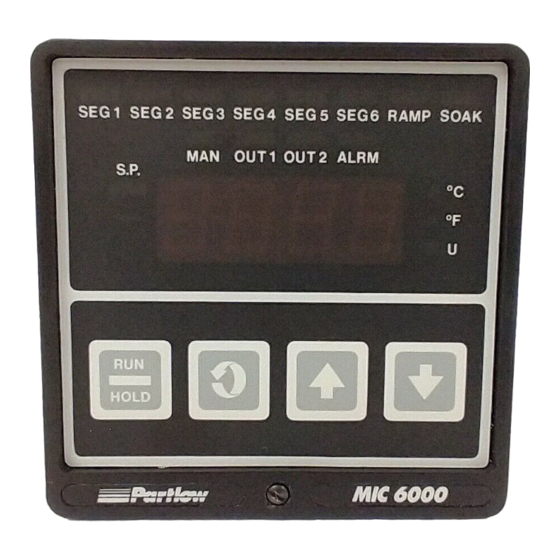
Table of Contents SECTION 1 - GENERAL Page Number 1.1 Product Description SECTION 2 - INSTALLATION & WIRING 2.1 Installation & Wiring 2.2 Unpacking 2.3 Location 2.4 Mounting 2.5 Preparation for Wiring 2.6 Wiring Connections SECTION 3 - CONFIGURATION 3.1 Configuration 3.2 Shipped Configuration/Jumper Positioning 3.3 Start up Procedure 3.4 Front Panel Operation... - Page 4 Figures and Tables Figure 1-1 Front Panel Display Figure 2-1 Installation View and Dimensions Figure 2-2 Noise Suppression Figure 2-3 Noise Suppression Figure 2-4 Wiring Connection Diagram Figure 2-5 AC Power Input Figure 2-6 Thermocouple Input Figure 2-7 RTD Input Figure 2-8 Volt, Millivolt, milliamp Input Figure 2-9A...
-
Page 5: Section 1 - General
Product Description 1.1 1.1.1 GENERAL This instrument is a microprocessor based profiling controller capable of measuring, displaying, and controlling a process variable from a variety of inputs. Applications include temperature, pressure, level, flow, and others. Control functions, alarm settings and other parameters are easily entered via the front keypad. - Page 6 1.1.3 CONTROL Instruments can be programmed for On-Off, Time Proportioning, Current Proportioning, or Position Proportioning control implementations. Selectable direct or reverse control action is also provided. Proportional control implementations are provided with fully programmable PID parameters. Automatic to Manual switching is easily accomplished via the Standby mode . Switching is bumpless, and while in manual, manipulation of proportional outputs is possible.
-
Page 7: Installation & Wiring
Installation and Wiring 2.1 Read these instructions carefully before proceeding with installation and operation. Electrical code requirements and safety standards should be observed. Installation should be performed by qualified personnel. CAUTION: The Instrument AC power input is specified in the model number and on the wiring label for either 115VAC or 230VAC. -
Page 8: Preparation For Wiring 2.5
FIGURE 2-1 4.8 (.188) MAX PANEL THICKNESS 165.9 (6.53) 146.8 (5.78) 96.0 90.4 (3.78) (3.560) Side View 96.0 (3.78) Mounting Bracket Panel 92 + or - 0.8 (3.622 + or - .031) PANEL 92+ or-.8 (3.622 CUTOUT + or-.031) SIZE 90.4 (3.560) Top View... - Page 9 2. If possible, eliminate mechanical contact relay(s) and replace with solid state relays. If a mechanical relay being powered by an instrument output device cannot be replaced, a solid state relay can be used to isolate the instrument. 3. A separate isolation transformer to feed only instrumentation should be considered. The transformer can isolate the instrument from noise found on the AC power input.
-
Page 10: Noise Suppression
2.5.1.5 NOISE SUPPRESSION AT THE SOURCE Usually when good wiring practices are followed, no further noise protection is necessary. Sometimes in severe electrical environments, the amount of noise is so great that it has to be suppressed at the source. Many manufacturers of relays, contactors, etc. supply "surge suppressors"... - Page 11 2.5.2 SENSOR PLACEMENT (Thermocouple or RTD) If the temperature probe is to be sufnected to corrosive or abrasive conditions, it should be protected by the appropriate thermowell. The probe should be positioned to reflect true process temperature: In liquid media - the most agitated area. In air - the best circulated area.
- Page 12 RTD LEAD RESISTANCE RTD lead length can affect instrument accuracy, since the size (gauge) and length of the wire affect lead resistance. To determine the temperature error resulting from the lead length resistance, use the following equation: Terr = TLe * L where;...
-
Page 13: Wiring Connections 2.6
Wiring Connections 2.6 All wiring connections are typically made to the instrument with it installed. Terminal connec- tions should be made via the rear panel with 14 gauge wire maximum (see Figure 2-4). FIGURE 2-4 REMOTE POS. PROP. SERIAL A RUN/ WIPER HOLD... -
Page 14: Thermocouple Input
FIGURE 2-5 AC Power Connect 115 VAC hot and neutral to terminals B and A respectively as illustrated below. Connect 230 VAC as described below. Connect Earth ground to the ground screw as shown. 115 VAC INSTRUMENT VOLTAGE 230 VAC INSTRUMENT VOLTAGE Rear View Rear View .25 AMP*... -
Page 15: Rtd Input
FIGURE 2-7 RTD Input Connections are shown for 3 wire and 2 wire RTD's. If a three wire device is used, install the common wires to terminals 1 and 5. If a two wire device is used, install a jumper between terminals 1 and 5. - Page 16 VOLT DC INPUT MILLIVOLT DC INPUT Rear View Rear View Shielded Twisted Shielded Twisted Pair Pair VOLT DC MILLIVOLT DC SOURCE SOURCE 5 VOLT DC 50 MILLIVOLT DC MAXIMUM MAXIMUM FIGURE 2-9A 24Volt Transmitter Power Supply (XP Option) Make connections as shown below. Terminal 3 is positive (+) and terminal 1 is negative (-). Be sure the input conditioning jumpers are properly positioned for the input type selected.
-
Page 17: Remote Run/Hold Input
FIGURE 2-10 Remote Run/Hold Input If Remote Run/Hold capability has been specified, make connections as shown. Terminal 5 is the ground and terminal 8 is the input. Shielded Multi-Conductor Cable Run/ Hold Out2 4-20mA Remote Out1 4-20mA Contact Return FIGURE 2-11 Remote Digital Communications RS-485 Terminals 7 &... -
Page 18: Alternate Remote Digital Communications
FIGURE 2-12 Alternate Remote Digital Communications RS-485 Terminals G & H (Optional) If the communications network continues on to other units, connect the shields together, but not to the instrument. A terminating resistor should be installed at the terminals of the last instrument in the loop. -
Page 19: Ssr Driver Output
RELAY C Rear View LOAD INPUT POWER GROUND FIGURE 2-14 SSR Driver Output Connections are made to the solid state relay driver output located in the Relay A position as shown. The solid state relay driver is a 5 VDC current sink output type. Connect the solid state relay driver(s) in the Relay B and C position (if present) in the same manner. -
Page 20: Current Output
FIGURE 2-15 mADC Output Connections are made to current outputs 1 and 2 as shown. Connect the positive lead to terminal 6 for Output 1 or terminal 7 for Output 2, the negative leads connect to terminal 5. Current outputs will operate up to 650 ohms maximum load. The current output(s) can be selected for either 4-20mADC or 0-20mADC (if EO option is present). -
Page 21: Section 3 - Configuration
Configuration 3.1 After completing installation of the unit, the configuration procedures contained within this section must be performed to prepare the instrument for operation on the intended application. The procedures include selecting specific parameters, entering data and possible jumper positioning. Parameter selections and data entry are made via the front keypad. -
Page 22: Shipped Configuration/Jumper Positioning
Associated with each mode is a series of unique displays which are accessed via the front keypad. Prior to first time operation of the instrument, the configuration procedures for the Program, Profile Entry and Tune modes must be performed as applicable. The Control, Off, Standby, Profile Continue and Profile execution (P1 thru P8) modes are discussed in Section 4.1 (page 38) of this manual. -
Page 23: Front Panel Operation 3.4
B. Upon power up, "6XXX" will be displayed (X representing digits), then "XXX-", identifying the seven digit model number as defined in the order matrix. Next, the software revision level will be displayed in the format "rX.XX". Then "tSt1", "tSt2", and "tSt3"... - Page 24 3.4.2 KEYPAD CONTROLS The keys on the keypad functions include: SCROLL: Used to: 1. Display the enabled modes and programmed profiles. 2. While in a mode, used to sequence the parameter codes and values. 3. Exit some Test and Calibration functions. 4.
-
Page 25: Operation Summary 3.5
Operation Summary 3.5 The configuration and operating modes, the method of moving from one mode to another, and the basic parameter functions are described in each individual section . Data and parameter entry is made by stepping through each mode and making an appropriate response or entry to each step. - Page 26 PROGRAM MODE FLOW CHART Prog rLyC inPS diSP iCor dPoS out1 o1PL out2 o2PL HySt out3 (SPuL - Option) SPLL Actual Display rLyA Option) On/Off Display - Use arrow keys AtFr rLyb to turn on or off Scroll Key Numeric Display - Use arrow keys to change value Up Arrow Key...
- Page 27 Com (Optional) CCon EO Option Co1r Co2r Pout...
- Page 28 DISPLAY AVAILABLE FACTORY YOUR STEP DESCRIPTION CODE SETTINGS SETTING SETTING Input Selection inPS 0=J T/C degrees C 1=J T/C degrees F 2=K T/C degrees C 3=K T/C degrees F 4=T T/C degrees C 5=T T/C degrees F 6=R T/C degrees C 7=R T/C degrees F 8=S T/C degrees C 9=S T/C degrees F...
- Page 29 DISPLAY AVAILABLE FACTORY YOUR STEP DESCRIPTION CODE SETTINGS SETTING SETTING Output 2 Percent Limit o2PL 0 to 100 % Output 3 out3 0=None 1=Process Alarm - Direct 2=Process Alarm - Reverse 3=Deviation Alarm - Direct 4=Deviaiton Alarm - Reverse 5=Deviation Band Alarm- Open withing band 6=Deviaiton Band Alarm- Closed within band...
- Page 30 DISPLAY AVAILABLE FACTORY YOUR STEP DESCRIPTION CODE SETTINGS SETTING SETTING Profile Time Base 1=HHH.T - Hours & Tenths 2=HH.MM - Hours & Min. 3=MM.SS - Minutes & Sec. EO Option 4=Units/Hr ramp rate; Hrs. & Tenths soak time 5=Units/Hr ramp rate; Hrs/Mins soak time 6=Units/Hr ramp rate;...
- Page 31 DISPLAY AVAILABLE FACTORY YOUR STEP DESCRIPTION CODE SETTINGS SETTING SETTING Parameters 29 - 31 are for Communications Option Only Communications CCon 0=Off 0, 4* Configuration 1=Monitor only (read only) 2=Normal mode (read and write) 3=Total Access with Limit Checking 4=Total Access without Limit Checking Communication 1=300 bits per second (bps)
-
Page 32: Tune Mode Configuration Procedures
TABLE 3-2 TUNE MODE CONFIGURATION PROCEDURE The Tune mode allows the entry, review or altering of the process control Tune adjustments and the alarm setting. To enter the Tune mode, press and release the SCROLL key until tunE is displayed, then press the DOWN key. - Page 33 TUNE MODE FLOW CHART tunE SPrd SEnS dbAL rSEt ArSt rAtE Actual Display On/Off Display - Use arrow keys to turn on or off Scroll Key Numeric Display - Use arrow keys to change value Up Arrow Key Down Arrow...
- Page 34 PROFILE ENTRY MODE FLOW CHART PEnt PLCt dhru dhrd PEnd Actual Display On/Off Display - Use arrow keys to turn on or off Scroll Key Numeric Display - Use arrow keys to change value Up Arrow Key Down Arrow...
-
Page 35: Profile Entry Mode Configuration Procedures
TABLE 3-3 PROFILE ENTRY MODE CONFIGURATION PROCEDURE Depress and release the SCROLL key until PEnt is displayed. Use the DOWN key to enter the Profile Entry mode. Depress the SCROLL key to scroll through the parameters and their values. Use the UP and DOWN keys to adjust the values. After adjusting a parameter, depress the SCROLL key to proceed to the next parameter. -
Page 36: Enable Mode Configuration Procedures
**All values except Profile Loop Count (PLCt) are initialized to zero and all event outputs are initialized to OFF, with the exception of the first profile. Profile Loop Count (PLCt) is set to 1. The first profile has the number of segments initialized to zero, to turn the profile OFF, but the profile has values stored in it for demonstration purposes. - Page 37 DISPLAY AVAILABLE FACTORY YOUR STEP DESCRIPTION CODE SETTINGS SETTING SETTING Program Mode EPro on or oFF Tune Mode Etun on or oFF Manual (Stby) Mode ESby on or oFF Profile Continue Mode on or oFF Profile Entry Mode on or oFF Setpoint Change ESPC on or oFF...
-
Page 38: Operation 4.1
Operation 4.1 4.1.1 OFF MODE In the Off Mode, the instrument control, process retransmission signal(s) and alarm function(s) are turned off. The Off mode can be entered by pressing and releasing the SCROLL key until the display reads oFF, then pressing the DOWN key. The display will read oFF and then the current process variable at two second intervals. - Page 39 Display Code Description Value Profile Number Actual Profile Number Time remaining in current Ramp or Soak Actual time remaining value (in whatever units were config ured in the program mode for Ptb) E1, E2, E3 Event 1-3 status (if applicable) on or oFF Current Setpoint Actual Setpoint Value...
-
Page 40: Profile Continue Mode
TABLE 4-1 PROFILE CONTINUE MODE - Not available when Ptb=4, 5, or 6 (EO Option only) DISPLAY STEP DESCRIPTION CODE ACTION Profile Number Press the SCROLL key to see the number of the last active profile. Profile Number Value If necessary, use the UP or DOWN key to change the profile number to the desired value, then press the SCROLL key. - Page 41 Profile Loop Count PLCt Press the SCROLL key to see the Remaining Profile Loop Count Remaining for the last active profile. Profile Loop Remaining If necessary, use the UP and DOWN key to adjust the Profile Loop Count Remaining value. To start a profile running, press the RUN/HOLD key while in the Profile Continue mode.
-
Page 42: Dual Output Control
4.1.2.7 POSITION PROPORTIONING CONTROL Position Proportioning control can be implemented on those controllers provided with two SPST relay outputs or two SSR Driver outputs and Slidewire Feedback option. Positioning proportioning control permits the use of PID control where the final control element is a modulating device such as a motorized valve. - Page 43 4.1.2.9 PROPORTIONAL OUTPUT PERCENTAGE DISPLAY While in the Control mode, press and hold the UP key and then press the SCROLL key to cause the display to sequence through a series of display codes and values: Percent Output 1 (if applicable) Output 1% value Percent Output 2 (if applicable) Output 2% value...
-
Page 44: Alarm Operation 4.2
4.1.5 SETPOINT RE-TRANSMISSION OUTPUT - EO OPTION ONLY If the instrument is provided with a current output not used for process control, this output may be assigned to provide a linear re-transmission of the setpoint value. The setpoint output is scaled for the application by using the Program mode parameters process/setpoint output value upper Pou and process/setpoint output value lower PoL. - Page 45 3. The change in setpoint, or disturbance, referenced above should be large enough to cause an observable deviation of process from setpoint. However, this change should not be so large that it will cause the controller output to proceed to either extreme limit. 4.
- Page 46 4. Achieve a response curve similiar to the sustained oscillation (curve C), this is the Ultimate Proportional Band (UPB) and Ultimate Time Period (UTP). a) If the response curve from step 3 does not damp out, as in Curve A from the drawing, the PB is too low.
-
Page 47: Service 5.1
Service 5.1 This section contains Calibration, Test and Trouble-shooting procedures that can be performed by the user. Instruments are calibrated to all input type specified when ordered at the factory prior to shipment. Re-calibration should not be necessary under normal operating conditions. -
Page 48: Calibration Procedures
TABLE 5-1 CALIBRATION PROCEDURES Calibration Procedure Description CAL 1 Re-initialization of Program and Tune mode values. CAL 2 Main Calibration used by all inputs. This is the only calibration requried for voltage and millivolt inputs. CAL 3 Cold Junction Compensation calibration used to correct for component variation in CJC circuit. - Page 49 NOTE: If the calibration reference number falls outside the -50 to +50 range, depress the SCROLL key and CAL2 will be displayed. Depress the DOWN key and perform the calibration once more. Repeat the calibration until the number falls within the toler- ance limits.
- Page 50 5.2.4 CAL4 COLD JUNCTION UTILITY This procedure displays the temperature the cold junction compensator is sensing. No test equipment is required. With CAL4 displayed, press and hold the DOWN key, then press the SCROLL key. Release both keys and SCAn will be displayed for 10 seconds while the instrument senses the CJC temperature.
- Page 51 5.2.7 CAL8 PROFILE REINTIALIZATION This procedure is used to erase all profiles that have been entered in the instrument. Be sure to record any profile information on the Profile Recording Sheets (Appendix F, pages 78 and 79) so that they can be re-entered. With CAL8 displayed, press and hold the DOWN key, then press the SCROLL key.
-
Page 52: Test Mode Procedures 5.3
Test Mode Procedures 5.3 To enter the Test mode, press and release the SCROLL key until tESt appears on the display, then press the DOWN key. tSt1 will be displayed, press and release the SCROLL key to advance the display to the desired test. Test 1, 2 and 3 are performed as a unit so the display will advance directly to tSt4 from tSt1. -
Page 53: Test Procedures And Description
TABLE 5-2 TEST PROCEDURES AND DESCRIPTION Test Description Test 1 Microprocessor internal RAM test. Used to check the processor RAM to make sure it is functioning correctly. Test 2 External RAM test, used to test the RAM chip for proper function. Test 3 EPROM checksum test, used the check that the EPROM program is correct. -
Page 54: Page
5.3.4 TEST 4 EXTERNAL RAM CHECKSUM TEST This is a checksum test to verify the integrity of data stored in RAM and indicate the number of times the instrument has had an Error 16, 17 and 18. The unit may have automatically recovered from these errors. - Page 55 5.3.8 TEST 8 CURRENT OUTPUT 2 TEST This test is the same as Test 7 except that it is for Output 2. 5.3.9 TEST 9 AUXILIARY INPUT TEST This test allows the operator to verify that the auxiliary inputs used for motor modulation feedback and remote Run/Hold contact closure are functioning properly.
-
Page 56: Trouble-Shooting And Diagnostics 5.4
Trouble-shooting and Diagnostics 5.4 This section consists of two columns. The first column is a list of some possible instrument conditions. The second column is a list of steps that should improve the condition. The steps should be performed in order until the condition improves or all the steps have been com- pleted. - Page 57 2. Turn off the power to the instrument. Press and hold the UP and DOWN keys and turn on the power. Keep the keys depressed until the model number resets to 6100-000. Release the keys and turn off the power. 3.
- Page 58 (Continued from page 57) Relay A Terminal C Relay B Terminal E Relay C Terminal G Return the instrument to the case and tighten the front panel screw. Turn the power on to the instrument and check the operation of the output(s). mADC Output(s) 1.
- Page 59 2. Measure the resistance of the Slidewire segment. The minimum resistance must be 135 ohms, the maximum 10 K ohms. 3. Perform the Auxiliary Input Test, Test 9 as described in the Test section (page 55). The voltage indicated should be between 0 and 5 VDC. 4.
- Page 60 Er5 - No Zero Crossings 1. Turn off the power to the instrument. Wait 5 seconds Detected and turn the power on. 2. Turn off the power to the instrument. Loosen the front panel screw and remove the instrument from the housing.
- Page 61 Er10 - ADC Reference 1. Perform the CAL2 procedure as described in the Voltage Error Calibration section (page 48). Er11 - Cold Junction 1. Be sure the Cold Junction Sensor is firmly attached Compensation Error to terminals 2 and 4. 2.
- Page 62 Er18 - Profile Data 1. Record all Profile data that was entered. Perform Checksum Error the CAL8 procedure as described in the Calibration section (page 51). Re-enter the Profile data as needed. Er19 - Tried to run profile 1. Press the RUN/HOLD key, then press and release the with 0 segments SCROLL key until oFF or CtrL are displayed, then press the DOWN key.
-
Page 63: Power Supply Board
Appendix A Board Layout - Jumper Positioning FIGURE A-1 - Power Supply Board RELAY C FRONT OF UNIT 115 VAC JUMPER POSITION RELAY B RELAY A COMPONENT SIDE 230 VAC JUMPER POSITION 230 VAC UNITS MAY BE FIELD CONVERTED TO 115 VAC BY MOVING JUMPERS AS SHOWN ABOVE . -
Page 64: Processor Board
FIGURE A-2 - Processor Board JU12 MICRO FRONT OF UNIT EPROM BATTERY COMPONENT SIDE JU12 ENABLE MODE T/C,mV,RTD, LOCKED IF NO CAL2 OPTION ENABLE MODE BOARD VOLT UNLOCKED... -
Page 65: Option Board (Revision D And Below)
FIGURE A-3 - Option Board - Revision D and below FRONT OF UNIT For 2nd 4-20mA, U5 is populated For 1st 4-20mA, U1 is populated COMPONENT SIDE 2ND 4-20 mADC T/C, mV, VOLT MOTOR MODULATION/ (NON-RTD) POSITION PROPORTIONING POTENTIOMETER REMOTE SETPOINT DIGITAL COMMUNICATIONS... -
Page 66: Option Board (Revision E And Above)
FIGURE A-3 - Option Board - Revision E and above JU14 JU13 2nd 4-20 T/C, mV, V T/C, mV, V Position Prop. RS-485 Com & 2nd 4-20 Pos. Prop. & Alt. Com RSP & RRH & JU13 JU14 Alt. No XPS No XPS J15 - AC Input XPS cable from transformer J16 - XPS to Relay C... -
Page 67: Glossary
Appendix B Glossary Assured Soak Assured Soak refers to the ability of the instrument to be programmed to interrupt the Soak segment time down if the process value exceeds a deviation value selected in the Profile Entry mode from the setpoint. The Soak timer will restart from where it was stopped when the process value does not exceed the deviation value selected from setpoint. - Page 68 Hysteresis This parameter is adjustable from 0 to 300 units representing the width of the band (half above and half below setoint). Used with On-Off or Alarm outputs to reduce cycling. For instance, with a value of 4 and a setpoint of 70, the output will turn On when the process variable drops to 68 and stay On until 72 is reached, then turn Off the output.
- Page 69 Rate (Derivative) This parameter is adjustable from 0.0 to 10.0 minutes and specifies how the control action responds to the rate of change in the process variable. For example, if the process variable is rising rapidly to setpoint, power is turned off sooner than it would be if the rise were slow. In effect, derivative action anticipates lags within the system and shifts the proportioning band by an amount determined by the rate of change of the input sensor.
-
Page 70: C - Order Matrix
Appendix C - Order Matrix Input 1 T/C or mV 2 Volts/mA 3 RTD 4 All Inputs Output Group 1 Control Output 1 and/or Event 1 Relay 2 SSR Driver 3 4-20 mA & Relay 4 4-20 mA & SSR Driver Output Group 2 Control Output 2 and/or Event... -
Page 71: D - Specifications
Appendix D Product Specifications Measurement Error Limit • Type J, K, T, E, N, C, T/C's and RTD +/-.25% of reading plus 1 degree @ 25 degrees C • Type R, S, B T/C's +/- .25% of span @ 25 degrees C •... - Page 72 THERMOCOUPLE TYPE RANGE TYPE RANGE -130 to 760°C 0 to 750°C -200 to 1400°F 0 to 1400°F -130 to 1370°C 200 to 1800°C -200 to 2500°F 400 to 3300°F -200 to 400°C 0 to 1300°C -330 to 750°F 0 to 2370°F 200 to 1650°C 200 to 2300°C 400 to 3000°F...
- Page 73 ALARM ADJUSTMENTS Process Alarm -9999 to 9999 units Deviation Alarm -3000 to 3000 units Deviation Band Alarm 1 to 3000 units CONTROL OUTPUTS Relay SPST 115VAC: 5.0A Resistive; 1/8HP or 250VA 230VAC: 2.5A Resistive; 1/8HP or 250VA SSR Driver Open collector output Short circuit protected @ 100mA maximum.
- Page 74 PROFILE PARAMETERS Programmable Profiles 8 user programmable profiles Segments 1 to 6 segments per profile Ramp and Soak 1 ramp and soak per segment Profile Time Base Selectable: HHH.T (hours and tenths) HH.MM (hours and minutes) MM.SS (minutes and seconds) EO Option: Units per hour ramp rate, HHH.T soak time Units per hour ramp rate, HH.MM soak time...
-
Page 75: E - Software Record/Reference Sheet
Appendix E Software Reference/Record Sheet PROGRAM MODE TUNE MODE InPs SPrd Icor out 1 o1PL dbAL out 2 Pb 1 o2PL Pb 2 out 3 rSET rLyA ArSt rLyb rAtE rLyC Ct 1 dISP Ct 2 dPOS SEns ENABLE MODE HySt ENAB EtSt... - Page 76 PLCt PLCt dhru dhru dhrd dhrd PEnd PEnd PLCt PLCt dhru dhru dhrd dhrd PEnd PEnd...
- Page 77 PLCt PLCt dhru dhru dhrd dhrd PEnd PEnd PLCt PLCt dhru dhru dhrd dhrd PEnd PEnd...
-
Page 78: Profile Development Sheet
Appendix F Profile Development Sheet The Profile Development Worksheet is intended to assist the Profile Controller customers. By filling in the worksheet with the application requirements, profile information can easily be obtained for entry into the instrument. The worksheet is a convenient record of the profile for future use. - Page 79 Profile Worksheet Profile Number Number of Segments Segments Ramp Soak Ramp Soak Ramp Soak Ramp Soak Ramp Soak Ramp Soak Time Time Time Time Time Time Time Time Time Time Time Time Setpoint Scale Event 1 Event 2 Event 3 Profile End Action Profile Loop Count Deviation Hold After Ramp Up...
- Page 80 Sample Profile The following is a sample profile intended to assist in understanding how the profile controller functions. Be sure to disconnect all control outputs before running this profile. Press and release the SCROLL key until Prog appears on the display then press the DOWN key.
-
Page 81: Warranty
Warranty and Return Statement These products are sold by the factory under the warranties set forth in the following para- graphs. Such warranties are extended only with respect to a purchase of these products, as new merchandise, directly from the factory or from a factory distributor, representative or reseller, and are extended only to the first buyer thereof who purchases them other than for the purpose of resale. - Page 82 THE PARTLOW-WEST COMPANY 2 CAMPION ROAD • NEW HARTFORD, NY 13413 USA 1-800-866-6659 • 315-797-2222 • FAX 315-797-0403...
Need help?
Do you have a question about the MIC 6000 and is the answer not in the manual?
Questions and answers