
Related Manuals for Partlow MIC 2000


Summary of Contents for Partlow MIC 2000
- Page 1 MIC 2000 Form 2844 Edition 11 © August 1993 Updated March 1997 Installation, Wiring, Operation Manua Brand...
- Page 2 nformation in this installation, wiring, and operation manual is subject to change without notice. One manual is provided with each instrument at the time of shipment. Extra copies are available at the price published on the front cover. Copyright © August 1993, all rights reserved. No part of this publication may be reproduced, transmitted, tran- scribed or stored in aretrieval system, or translated into any language in any form by any means without the writ-...
-
Page 3: Table Of Contents
Table of Contents SECTION 1 - GENERAL Page Number 1.1 Product Description SECTION 2 - INSTALLATION & WIRING 2.1 Installation and Wiring 2.2 Preparation for Wiring 2.3 Input Connections 2.4 Output Connections SECTION 3 - CONFIGURATION & OPERATION 3.1 Configuration and Operation 3.2 Operation Summary 3.3 Configuration Summary 3.4 Tune Mode Operation... - Page 4 FIGURES & TABLES Figure 1-1 Controller Display Illustration Figure 2-1 Panel Opening Sizes and Installation Figure 2-2 Noise Suppression Figure 2-3 Noise Suppression Figure 2-4 Wiring Label Figure 2-5 AC Power Figure 2-6 Thermocouple Input Figure 2-7 RTD Input Figure 2-8 Volt, mV, mADC Input Figure 2-9A 24VDC Transmitter Power Supply...
-
Page 5: Section 1 - General
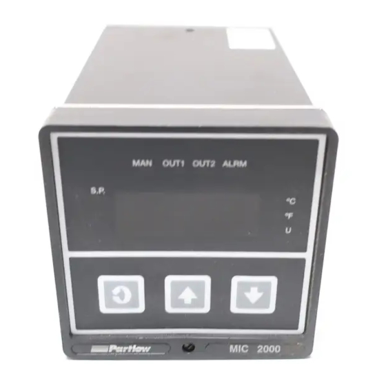
Product Description 1.1 1.1.1 GENERAL This instrument is a microprocessor based single loop controller capable of measuring, displaying and controlling temperature, pressure, flow, and level from a variety of inputs. Control functions, alarm settings and other parameters are easily entered through the front keypad. - Page 6 1.1.3 CONTROL The instrument can be programmed for on-off, time proportioning, current proportioning, or position proportioning control implementations depending on the model number. A second control output is an available option. Proportional control implementations are provided with fully programmable separate PID parameters. 1.1.4 ALARM Alarm indication is standard on all instruments.
-
Page 7: Installation And Wiring 2.1
Installation and Wiring 2.1 Prior to proceeding with installation, verify the AC power input required by the instrument. AC power input is either 115 VAC or 230 VAC and is specified in the model number and on the wiring label affixed to the instrument housing. See Figure 2-4 (page 13) for a wiring label description. -
Page 8: Preparation For Wiring 2.2
Preparation for Wiring 2.2 2.2.1 WIRING GUIDELINES Electrical noise is a phenomenon typical of industrial environments. The following are guidelines that must be followed to minimize the effect of noise upon any instrumentation. 2.2.1.1 INSTALLATION CONSIDERATIONS Listed below are some of the common sources of electrical noise in the industrial environ- ment: •... -
Page 9: Noise Suppression
In applications where a High Voltage Transformer is used, (i.e. ignition systems) the secon- dary of the transformer should be isolated from all other cables. This instrument has been designed to operate in noisy environments, however, in some cases even with proper wiring it may be necessary to suppress the noise at its source. 2.2.1.4 USE OF SHIELDED CABLE Shielded cable helps eliminate electrical noise being induced on the wires. - Page 10 Contacts - Arcing may occur across contacts when the contact opens and closes. This results in electrical noise as well as damage to the contacts. Connecting a RC network properly sized can eliminate this arc. For circuits up to 3 amps, a combination of a 47 ohm resistor and 0.1 microfarad capacitor (1000 volts) is recommended.
- Page 11 THERMOCOUPLE LEAD RESISTANCE Thermocouple lead length can affect instrument since the size (gauge) and the length of the wire affect lead resistance. To determine the temperature error resulting from the lead length resistance, use the following equation: Terr = TLe * L where;...
- Page 12 RTD LEAD RESISTANCE RTD lead length can affect instrument accuracy, since the size (gauge) and length of the wire affect lead resistance. To determine the temperature error resulting from the lead length resistance, use the following equation: Terr = TLe * L where;...
-
Page 13: Input Connections 2.3
FIGURE 2-4 WIRING LABEL POS.PROP. REMOTE SERIAL A SETPT + WIPER RELAY C OUT2 POS.PROP. SERIAL B 4-20mA HIGH OUT1 4-20mA RELAY B RETURN INPUT RATINGS: 115/230 VAC 50/60 HZ 15VA MAX RELAY OUTPUT RATINGS: RELAY A 115VAC 5.0A RESISTIVE 230VAC 2.5A RESISTIVE SIGNAL + 230VAC 1/8 HP... -
Page 14: Thermocouple Input
FIGURE 2-6 Thermocouple (T/C) Input Make thermocouple connections as illustrated below. Connect the positive leg of the thermo- couple to terminal 3, and the negative to terminal 1. For industrial environments with com- paratively high electrical noise levels, shielded thermocouples and extension wire are recom- mended. -
Page 15: Volt, Mv, Madc Input
FIGURE 2-8 Volt, mV, mADC Input Make volt, millivolt and milliamp connections as shown below. Terminal 3 is positive and terminal 1 is negative. Milliamp input requires a 250 ohm shunt resistor (supplied with the instrument) installed across the input terminals and by configuring the instrument for either 0 to 5 or 1 to 5 VDC input. - Page 16 FIGURE 2-9A 24 Volt Transmitter Power Supply (XP Option) Make connections as shown below. Terminal 3 is positive (+) and terminal 1 is negative (-)/ Be sure the input conditioning jumpers are properly positioned for the input type selected. See Figure A-2 Processor Board, page 60, and Figure A-3 Option Board, page 61 or 62. Note the 250 ohm shunt resistor is not required.
-
Page 17: Remote Setpoint Input
FIGURE 2-10 Remote Setpoint Input - VDC, mADC and Potentiometer Input connections are illustrated below. Terminal 8 is positive and terminal 5 is negative. The remote setpoint input can be configured for either 0 to 5VDC or 1 to 5 VDC input. Make sure that the voltage input matches the voltage configuration selected in the Program mode. -
Page 18: Remote Digital Communications
FIGURE 2-11 Remote Digital Communications RS 485 Terminals 7 & 8 If the communications network continues on to other units, connect the shields together, but not to the instrument. A terminating resistor should be installed at the terminals of the last instrument in the loop. -
Page 19: Output Connections 2.4
Output Connections 2.4 FIGURE 2-12 Relay Output Connections are made to relay A as illustrated below. Connect relay(s) B & C (if present) in the same manner. Relay contacts are rated at 5 amp Resistive load 115 VAC. RELAY A RELAY B Rear View Rear View... -
Page 20: Ssr Driver Output
FIGURE 2-13 SSR Driver Output Connections are made to the solid state relay driver output located in the Relay A position as shown. The solid state relay driver is a 5 VDC current sink output type. Connect the solid state relay driver(s) in the Relay B and C position (if present) in the same manner. SSR DRIVER (RELAY A) SSR DRIVER (RELAY B) Rear View... -
Page 21: Madc Output
FIGURE 2-14 mADC Output Connections are made for current outputs 1 or 2 as shown below. Connect the positive lead to terminal 6 for Output 1 or terminal 7 for Output 2 , the negative leads connect to terminal 5. Current outputs will operate up to 650 ohms maximum load. -
Page 22: Configuration And Operation 3.1
Configuration and Operation 3.1 3.1.1 POWER UP PROCEDURE Verify all electrical connections have been properly made before applying power to the instrument. If the instrument is being configured (set up) for the first time, it may be desirable to discon- nect the controller output connections. - Page 23 UP KEY This key is used to: 1. Increase displayed parameter value 2. View setpoint (press and release) 3. Increase setpoint (press and hold) 4. With a parameter code displayed A. Press once to exit mode B. Press twice to enter Control mode 5.
-
Page 24: Configuration Summary 3.3
Configuration Summary 3.3 All configurable parameters are provided in Tables 3-1 thru 3-3 on the following pages. These tables illustrate the display sequence, parameter adjustment and factory setting for each step. The instrument is provided with a “time-out” feature. If the instrument is in any mode, other than the Control mode, and no keypad activity takes place for 30 seconds, the mode will be exited automatically. - Page 25 ENABLE MODE FLOW CHART EnAb EtSt ECAL EPro Etun ESbY ESPS ESPC K e y Actual Display On/Off Display - Use arrow keys to turn on or off Scroll Key Numeric Display - Use arrow keys to change value Up Arrow Key Down Arrow...
- Page 26 PROGRAM MODE Prog rLyC inPS diSP iCor dPoS out1 o1PL out2 o2PL HySt out3 K e y rSPu rLyA Actual Display On/Off Display - Use arrow keys to turn on or off rSPL rLyb Scroll Key Numeric Display - Use arrow keys to change value Up Arrow Key Down Arrow...
- Page 27 Pout (SPuL - EA Option) SPLL Option) AtFr PorA EA Option PoAP EB Option SPrr FSCn Com Option Prnd CCon Co1r Co2r...
-
Page 28: Program Mode Configuration Procedures
TABLE 3-2 PROGRAM MODE CONFIGURATION PROCEDURE Press and release the SCROLL key until Prog is displayed. Use the DOWN key to enter the Program mode. Depress and release the SCROLL key to advance the display through the parameters and their values. Use the UP and DOWN keys to adjust the parameter values. After adjusting a parameter, depress the SCROLL key to proceed to the next parameter. - Page 29 S T E P DESCRIPION DISPLAY AVAILABLE F A C T O R Y YOUR CODE SETTINGS SETTING SETTING Output 2 out2 0 = None Position Proportioning Direct (Close) 1 = On-Off Direct (Cooling) 2 = On-Off Reverse (Heating) 3 = Time Proportioning- Direct (Cooling) 4 = Time Proportioning-Reverse (Heating)
- Page 30 S T E P DESCRIPTION DISPLAY AVAILABLE F A C T O R Y YOUR CODE SETTINGS SETTING SETTING Remote Setpoint rSPu -9999 to 9999°/Units 1400* Upper Value Remote Setpoint rSPL -9999 to 9999°/Units Lower Value Setpoint -9999 to 9999°/Units 1400* Upper Limit (SPuL - EA Option)
- Page 31 S T E P DESCRIPTION DISPLAY AVAILABLE F A C T O R Y YOUR CODE SETTINGS SETTING SETTING Percent Output PorA 0 = None Relay Actuation 1 = Based upon proportional Output 1 On when process is above PoAP 2 = Based upon proportional Output 1 On when process is...
- Page 32 Address TUNE MODE FLOW CHART tunE SPrd SEnS dbAL rSEt ArSt K e y Actual Display rAtE On/Off Display - Use arrow keys to turn on or off Scroll Key Numeric Display - Use arrow keys to change value Up Arrow Key Down Arrow...
-
Page 33: Tune Mode Configuration Procedures
TABLE 3-3 TUNE MODE CONFIGURATION PROCEDURE Depress the SCROLL key until tunE is displayed. Use the DOWN key to enter the Tune mode. Depress and release the SCROLL key to sequence through the parameters and their values. Use the UP and DOWN keys to adjust the values. After adjusting a parameter, depress the SCROLL key to proceed to the next parameter. -
Page 34: Tune Mode Operation 3.4
Tune Mode Operation 3.4 Proportional output control may require the adjustment (tuning) of the PID and other related parameters. This provides a means for the instrument's control algorithm to be adjusted to meet specific application requirements. 3.4.1 SYSTEMATIC TUNING METHOD 1. - Page 35 3.4.2 ZIEGLER NICHOLS TUNING METHOD This procedure has been determined empirically to yield 1/4 amptitude decay tuning parame- ters that are determined by watching the system in a sustained oscillation (curve C, page 36, the ultimate proportional band and ultimate time period) and then using these values from this sustained oscillation to calculate ideal parameters.
- Page 36 Period Curve A : unstable Curve B : stable Curve C : continuously cycling, ultimate PB and period...
-
Page 37: Control Capability 4.1
Control Capability 4.1 A variety of user programmable control features and capabilities are available including: • On-Off Control • Time Proportioning Control • Current Proportioning • Position Proportioning Control • Alarm Functions • Dual Output Control • Auto/Manual Switching • Automatic Transfer •... -
Page 38: On-Off Control / Latched On-Off 4.4
On-Off Control / Latched On-Off 4.4 On-Off control can be implemented with SPST relay or SSR driver output(s) . On-Off operation can be assigned to either or both Output 1 and 2. A hysteresis adjustment is provided for On-Off Outputs. This adjustment is in terms of degrees/engineering units and defines the bandwidth of the hysteresis. -
Page 39: Proportional Bandwidth Effect On Output
A Position Proportioning sensitivity adjustment is provided, which specifies a deadband around the setpoint to prevent the valve from oscillating. The valve rotation time must be entered, for proper operation, into the Tune mode paramter Ct1. See Figure 4-1 for proportional bandwidth effect on the output. FIGURE 4-1 Proportional Bandwidth Effect On Output 100%... -
Page 40: Dual Output Control 4.8
Dual Output Control 4.8 Dual output control can be performed when two outputs are specified. The outputs may be programmed for On-Off, Time Proportioning, or Current Proportioning, as applicable. The output action is dependent upon the setpoint, the process value, and Tune mode parame- ters. -
Page 41: Manual Operation Of Proportional Outputs 4.9
Manual Operation of Proportional Outputs 4.9 The Auto/Manual switching function applies to proportional control outputs only. Switching between the automatic and manual control modes is accomplished by scrolling to the Standby mode and pressing the DOWN key to enter the mode. Switching from automatic to manual is always bumpless. -
Page 42: Setpoint Adjustments 4.11
Setpoint Adjustments 4.11 Local Local setpoint adjustment is accomplished by using the keypad. Press the UP key to increase the setpoint value. Press the DOWN key to decrease the setpoint value. Holding the key pressed will cause the value to change slowly at first then increasingly faster. The range of the setpoint value can be limited by selecting the setpoint upper limit SPL in the Program mode. - Page 43 Process Re-transmission Output - EA Option Only If the instrument is provided with a current output not used for process control, this output may be assigned to provide a linear re-transmission of the process value. This output can be used to provide a process signal to remotely installed recorders, panel meters, or data loggers.
-
Page 44: Service 5.1
Service 5.1 This section contains Calibration , Test and Trouble-shooting procedures that can be per- formed by the user. Instruments are calibrated to its input type at the factory prior to ship- ment. Re-calibration should not be necessary under normal operating conditions. Calibration 5.2 Caution: Do not attempt any of these calibrations without the proper test equipment with specifications equal to or better than those listed. -
Page 45: Calibration Procedures
TABLE 5-1 CALIBRATION PROCEDURES Calibration Procedure Description CAL 1 Re-initialization of Program and Tune Mode values. CAL 2 Main Calibration used by all inputs. This is the only calibration required for voltage and millivolt inputs. CAL 3 Cold Junction Compensation calibration used to correct for component variation in CJC circuit. - Page 46 Error Recovery - see 5.4 (page 52) for details. However, be sure that the millivolt source is securely connected, functioning properly and the polarity is correct. Press the DOWN key to bring the instrument back to dELy and try the calibration again. The calibration can be exited at anytime hLd1 or the reference number is displayed by pressing the SCROLL key.
- Page 47 5.2.5 CAL 5 RTD INPUT This procedure determines and saves calibration values which correct for component vari- ations relating to RTD inputs. This calibration must be preceded by CAL2 to properly calibrate the unit. Test equipment needed will include a Decade Box (Resistance Substitution ) with .01% resolution or equivalent.
-
Page 48: Test Mode 5.3
Test Mode 5.3 The Test mode can be entered, if enabled, by pressing and releasing the SCROLL key until tESt is displayed. Press the DOWN key and tSt1 will be displayed. This test can be initiated at this time or press the SCROLL key to advance to the desired test. Test 1, 2 and 3 are performed as a block so the display will advance from tSt1 to tSt4. -
Page 49: Test Procedures And Description
TABLE 5-2 TEST PROCEDURES AND DESCRIPTION TEST DESCRIPTION Test 1 Microprocessor internal RAM test.; used to verify that the processor RAM is functioning correctly. Test 2 External RAM test; used to test the instrument’s RAM for proper function. Test 3 EPROM checksum test;... - Page 50 5.3.5 TEST 5 - KEYPAD/DISPLAY TEST This test allows the operator to verify that the keys work and that all display elements can be lighted. No special test equipment is required for this test. With tSt5 displayed press and hold the DOWN key then press the SCROLL key. The display will go blank. Release both keys, then press each key to be tested.
- Page 51 5.3.9 TEST 9 - AUXILIARY INPUT TEST This test allows the operator to verify that the auxiliary inputs used for position proportioning (slidewire) feedback or remote setpoint is functioning properly. A variable voltage source, 5 VDC will be required to execute this test. With tSt9 displayed, press and hold the DOWN key then press the SCROLL key.
-
Page 52: Troubleshooting And Diagnostics
Trouble-shooting and Diagnostics 5.4 This section consists of two columns. The first column is a list of some possible instrument conditions. The second column is a list of steps that should improve the condition. The steps should be performed in order until the condition improves or all the steps have been tried. If the instrument condition has not improved, contact the nearest representative or the factory for assistance. - Page 53 2. Turn off the power to the instrument. Press and hold the UP and DOWN keys and turn on the Note: To re-initialize, follow power. Keep the keys depressed until the model steps 2 & 3. number resets to 2100-000. Release the keys and turn off the power.
- Page 54 (Continued from page 53) Return the instrument to the case and tighten the front panel screw. Turn the power on to the instrument and check the operation of the output(s). mADC Output(s) 1. Verify that the Program and Tune mode Malfunction parameters are correctly set (page 28 &...
- Page 55 rSEr 1. Check that the Remote Setpoint signal is present Remote Setpoint Error and of the correct polarity between terminals 8 (+) and 5 (-). 2. Perform the Auxiliary Input Test, Test 9 as described in the Test section (page 51), the voltage indicated during the test should be the same as measured in the preceeding step.
- Page 56 Er 4 - RTD Mismatch Error 1. Check the connections to the instrument for the RTD Input Calibration CAL5 as described in the Calibration section (page 47). Repeat the RTD Input Calibration. Er 5 - No Zero Crossings 1. Turn off the power to the instrument. Wait 5 Detected seconds and turn the power on.
- Page 57 Er10 - ADC Reference Voltage 1. Perform the CAL2 procedure as described in the Error Calibration section (page 45). Er 11 - Cold Junction 1. Be sure the Cold Junction Sensor is firmly Compensation Error attached to terminals 2 and 4. 2.
- Page 58 Er 36 - Incorrect Crystal 1. Turn off the power to the instrument, wait 5 seconds, For Digital Comm. then turn the power on. 2. Check crystal, Y1, for 11 MHZ (see Appendix A-2, Page 60). Er 37 - Incorrect Micro. 1.
-
Page 59: A - Board Layout - Jumper Positioning
Appendix A Board Layout - Jumper Positioning FIGURE A-1 - Power Supply Board RELAY C FRONT OF UNIT 115 VAC JUMPER POSITION RELAY B RELAY A COMPONENT SIDE 230 VAC UNITS MAY BE FIELD CONVERTED TO 115 VAC BY MOVING JUMPERS AS SHOWN ABOVE . -
Page 60: Figure A-2 Processor Board
FIGURE A-2 - Processor Board Revision L, M and M2 Located on solder side MICRO FRONT OF UNIT EPROM BATTERY COMPONENT SIDE ENABLE MODE T/C,mV,RTD,CAL2 LOCKED IF NO OPTION BOARD ENABLE MODE VOLT UNLOCKED Note: Locked and unlocked positions differ from Rev J and below and M3 and above. -
Page 61: Figure A-3 Option Board
FIGURE A-3 - Option Board, Revision E and above (For Rev. D and below, see next page) JU14 JU13 2nd 4-20 T/C, mV, V T/C, mV, V *Position Prop. RS-485 Com & 2nd 4-20 *Pos. Prop. & Alt. Com RSP & RRH &... -
Page 62: Figure A-3 Option Board
FIGURE A-3 - Option Board, Revision D and below FRONT OF UNIT For 2nd 4-20mA, U5 is populated For 1st 4-20mA, U1 is populated COMPONENT SIDE 2ND 4-20 mADC T/C, mV, VOLT MOTOR MODULATION/ (NON-RTD) POSITION PROPORTIONING POTENTIOMETER REMOTE SETPOINT DIGITAL COMMUNICATIONS T/C , mV , VOLT... -
Page 63: B - Glossary Of Terms
Appendix B Glossary of Terms Automatic Reset (Integration) Automatic reset is a Tune mode parameter that will bias the proportional output(s) to compen- sate for process load variations. This parameter is adjustable from 0.0 to 100.0 repeats per minute. Factory default is 0.0. The display codes is ArSt. Automatic Transfer Automatic transfer is a Program mode parameter that will allow the instrument to switch from the Manual to the Control mode of operation automatically when the process value reaches... - Page 64 Hysteresis This parameter is adjustable from 0 to 300 units representing the width of the band (half above and half below setpoint). Used with On-Off or Alarm outputs to reduce cycling. For instance, with a value of 4 and a setpoint of 70, the output will turn On when the process variable drops to 68 and stays On until 72 is reached, then turns Off the output.
- Page 65 Rate (Derivative) This parameter is adjustable from 0.0 to 10.0 minutes and specifies how the control action responds to the rate of change in the process variable. For example, if the process variable is rising rapidly to setpoint, power is turned off sooner than it would be if the rise were slow. In effect, derivative action anticipates lags within the system and shifts the proportioning band by an amount determined by the rate of change of the input sensor.
-
Page 66: C - Model Number Hardware Matrix Details
Appendix C - Order Matrix Input 1 T/C or MV 2 Volts/MA 3 RTD 4 All Inputs Output 1 1 Relay 2 SSR Driver 3 4-20mA Output 2 0 None 1 Relay 2 SSR Driver 3 4-20mA Alarm 0 None 1 Relay 2 SSR Driver Remote... -
Page 67: D - Specifications
Appendix D - Specifications Input Specifications THERMOCOUPLE TYPE RANGE TYPE RANGE -130 TO 760C 0 TO 750C -200 TO 1400F 0 TO 1400F -130 TO 1370C 200 TO 1800C -200 TO 2500F 400 TO 3300F -200 TO 400C 0 TO 1300C -330 TO 750F 0 TO 2370F 200 TO 1650C... - Page 68 Output Specifications CONTROL OUTPUT 1 AND 2 Relay Output SPST 115 VAC: 5.0 A Resistive; 1/8HP or 250 VA 230 VAC: 2.5 A Resistive; 1/8HP or 250 VA SSR Driver Open collector output Short circuit protected at 100 mA maximum Provides 4 VDC at 20 mA or 3 VDC at 40 mA Current Output 0-20mADC or 4-20 mADC into 650 ohms maximum.
- Page 69 Performance Specifications Measurement Error Limit • Type J,K,T,E,N, & C thermocouples and RTD ± 0.25% of reading plus 1 degree at 25 degree C • Type R,S, & B thermocouple ± 0.25% of span at 25C • mVDC, mADC and VDC ± 0.25% of scaled span plus 1 least significant digit at 25 degrees C Ambient Temp.
-
Page 70: E - Software Record/Reference Sheet
Appendix E Software Record/Reference Sheet Program Mode Enable Mode Program Mode Continued InPs ENAB ICor EtSt SPrr out1 ECAL CCon o1PL EPro out2 Etun o2PL ESby out3 ESPS rLyA ESPC rLyb rLyC Tune Mode diSP SPrd dPoS dbAL HySt rSPu rSEt rSPL ArSt... - Page 71 Warranty and Return Statement These products are sold by the factory under the warranties set forth in the following para- graphs. Such warranties are extended only with respect to a purchase of these products, as new merchandise, directly from the factory or from a factory distributor, representative or reseller, and are extended only to the first buyer thereof who purchases them other than for the purpose of resale.
- Page 72 THE PARTLOW-WEST COMPANY 2 CAMPION ROAD • NEW HARTFORD, NY 13413 USA 1-800-866-6659 • 315-797-2222 • FAX 315-797-0403...
Need help?
Do you have a question about the MIC 2000 and is the answer not in the manual?
Questions and answers