
Related Manuals for Partlow MIC 1400


Summary of Contents for Partlow MIC 1400
- Page 1 MIC 1400 1/4 DIN MICROBASED CONTROLLER OPERATORS MANUAL FORM 3665 EDITION 1 © OCT. 1995 PRICE $10.00 Brand...
- Page 2 Partlow Corporation. This is the First Edition of the MIC 1400 manual. It was written and produced entirely on a desk-top-publishing system. Disk versions are available by written request to the Partlow Publications Department.
-
Page 3: Table Of Contents
Figure B-2 Output 2/Output 3 Removal Figure B-3 CPU PWA Figure B-4 PSU PWA with Relay or SSR Out.1 Figure B-5 PSU PWA with DC Output 1 Figure B-6 Option PWA (Continued on next page) Edition 1 MIC 1400 Manual... - Page 4 Figure 2-19 SSR Driver Output 3 Figure 2-20 mADC Output 3 Figure 4-1 Proportional Bandwidth Effect on Output Table 3-1 Enable Mode Configuration Procedures Table 3-2 Program Mode Configuration Procedures Table 3-3 Tune Mode Configuration Procedures MIC 1400 Manual Edition 1...
-
Page 5: Section 1 - General
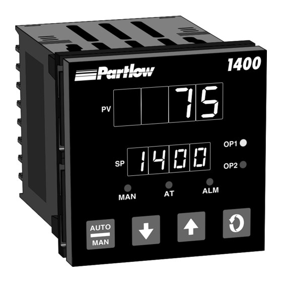
Alarm type may be set as Process Direct or Reverse (high or low), Deviation Direct or Reverse (above or below setpoint), Deviation Band Type (closed or open within band), or Loop Reverse or Direct. Alarm status is indicated by LED. Edition 1 MIC 1400 Manual... - Page 6 FIGURE 1-1 Keys and Indicators AUTO 1.1.5 PROCESS VARIABLE/SETPOINT VALUE RE-TRANSMISSION OUTPUT If the instrument is specified with this option, this output may be scaled over any desired range and re-transmitted. MIC 1400 Manual Edition 1...
-
Page 7: Installation & Wiring
92 mm ± 0.8 FIGURE 2-1 (3.62”± .031) Panel Cut-Out Dimensions PANEL 92 mm ± 0.8 CUTOUT (3.62”± .031) SIZE Edition 1 MIC 1400 Manual... -
Page 8: Figure 2-2 Main Dimensions
96 mm (3.78 in) Side View 10 mm (0.39 in.) 96 mm (3.78 in.) FIGURE 2-3 Panel Mounting the Controller Mounting Clamp Controller Housing Tongues on mounting clamp engage in ratchet slots on controller housing MIC 1400 Manual Edition 1... -
Page 9: Preparations For Wiring
The transformer can isolate the instrument from noise found on the AC power input. If the instrument is being installed on existing equipment, the wiring in the area should be checked to insure that good wiring practices have been followed. Edition 1 MIC 1400 Manual... - Page 10 The shield should be grounded at one end only. The pre- ferred grounding location is the sensor, transmitter or transducer. MIC 1400 Manual Edition 1...
- Page 11 For circuits up to 3 amps, a combination of a 47 ohm resistor and 0.1 microfarad capacitor (1000 volts) is recommended. For circuits from 3 to 5 amps, connect 2 of these in parallel. See Figure 2-5, page 12. Edition 1 MIC 1400 Manual...
- Page 12 If the temperature probe is to be subjected to corrosive or abrasive condi- tions, it should be protected by the appropriate thermowell. The probe should be positioned to reflect true process temperature: In liquid media - the most agitated area In air - the best circulated area MIC 1400 Manual Edition 1...
-
Page 13: Figure 2-6 Wiring Label
FIGURE 2-6 Wiring Label OUTPUT 3 Relay SSR/DC MAINS (LINE) SUPPLY No external connections to be made to these terminals RS485 SERIAL COMMS. SSR/DC N/O C Relay OUTPUT 2 Edition 1 MIC 1400 Manual... -
Page 14: Input Connections 2.3
3 as shown below. A jumper wire supplied by the customer must be installed between terminals 2 and 3. Input conditioning jumper must be positioned correctly (see Appendix B) and Hardware Definition Code must be correct (see Appendix C). MIC 1400 Manual Edition 1... - Page 15 1 is negative. Input conditioning jumper must be positioned correctly (see Appendix B) and Hardware Definition Code must be correct (see Ap- pendix C). FIGURE 2-11 Remote Digital Communications - RS485 Make digital communication connections as illustrated below. Edition 1 MIC 1400 Manual...
-
Page 16: Output Connections 2.4
Connections are made to Output 1 SSR Driver as illustrated below. The solid state relay driver is a non-isolated 0-4 VDC nominal signal. Output impedance is 250 ohms. FIGURE 2-14 mADC Output 1 Make connections for DC Output 1 as illustrated below. MIC 1400 Manual Edition 1... -
Page 17: Figure 2-15 Relay Output 2
Connections are made to Output 2 SSR Driver as illustrated below. The solid state relay driver is a non-isolated 0-4 VDC nominal signal. Output impedance is 250 ohms. FIGURE 2-17 mADC Output 2 Make connections for DC Output 2 as illustrated below. Edition 1 MIC 1400 Manual... -
Page 18: Figure 2-18 Relay Output 3
Connections are made to Output 3 SSR Driver as illustrated below. The solid state relay driver is a non-isolated 0-4 VDC nominal signal. Output impedance is 250 ohms. FIGURE 2-20 mADC Output 3 (Recorder Output Only) Make connections for DC output 3 as illustrated below. MIC 1400 Manual Edition 1... -
Page 19: Operation 3.1
Display enabled modes of operation. Display a mode parameter value. Advance display from a parameter value to the next parameter code. Activate the Pre-tune mode. With the DOWN key to view the current Hardware Definition Code setting. Edition 1 MIC 1400 Manual... - Page 20 *This display is available only if one or more of the alarms is/are energized. When "ALSt" is seen in the lower display, to enter the Program or Tune modes, press the UP key with "ALSt" displayed, then the SCROLL key to Program or Tune. MIC 1400 Manual Edition 1...
- Page 21 Flashes when the Manual mode has been entered Indicates when the Pre-Tune mode or Auto-Tune mode has been selected; flashing for Pre-Tune and continuously ON for Auto-Tune. 3.1.5 SETPOINT ADJUSTMENT 3.1.5.1 LOCAL SETPOINT To adjust the instrument setpoint, proceed as follows: Edition 1 MIC 1400 Manual...
- Page 22 SPRr not OFF and ESPr equal to 0 BLANK Ramping SP SPrP SPrP If ESPr is enabled, the display sequence changes to: BLANK Ramping SP BLANK *Ramp Rate SPrP SPrP SPrr SPrr *Adjustable MIC 1400 Manual Edition 1...
- Page 23 Output 1 only, and -100% to +100 % for instruments with both Output 1 and Output 2. To exit from the Manual mode, press the Auto/Manual key. Shifting to the Control mode is bumpless. Edition 1 MIC 1400 Manual...
-
Page 24: Configuration 3.2
After 5 more seconds, "EnAb" will be displayed. Release the keys, the display should show "EPro". Pressing the DOWN key will display the Enable mode codes in the following sequence: EPro - - Etun - - ESPC MIC 1400 Manual Edition 1... - Page 25 This display indicates all Tune mode parameters have been set to their default condition. To clear this condition, enter the Tune mode and make a parameter value change and review each parameter for its proper setting. Edition 1 MIC 1400 Manual...
- Page 26 =Rcdr Out P.V. rEcS =Rcdr Out S.P. LP_r =Loop Reverse LP_d=Loop Direct Ad_r =Rev Logic AND Ad_d=Dir Logic AND Or_r =Rev Logic OR Or_d=Dir Logic OR Al_r =Alm Rev Com Bit Rate 1200, 2400, 4800, 4800 9600 MIC 1400 Manual Edition 1...
- Page 27 SPrr 1 to 9999 units/hour Rate and OFF Input Filter Filt 0.0 to 100.0 seconds in .5 sec. increments ± Span Input Correct iCor Output 1% 0 to 100% Read Only (Continued on next page) Edition 1 MIC 1400 Manual...
- Page 28 0.1 to 10.0% of span Setpoint SPuL Span Max. Span Max. Upper Limit Setpoint SPLL Span Min. Span Min. Lower Limit Process -1999 to 9999 Span Max. Output Upper Process -1999 to 9999 Span. Min. Output Lower MIC 1400 Manual Edition 1...
- Page 29 Alarm 2 Band Alarm 2 bAL2 0 to Span ± Span Deviation dAL2 Alarm 2 Loop Alarm LAEn 0=Disable Enable 1=Enable Loop Alarm LAti 1 sec to 99 mins. 99 mins. Time 59 secs. 59 secs. Edition 1 MIC 1400 Manual...
- Page 30 1=Enable **Setpoint Ramp ESPr 0=Disable Rate Enable 1=Enable Comm. Enable CCon 0=Disable 1=Enable * Activates Pre-Tune on power-up when enabled. ** When enabled, allows user to change ramp rate without having to enter Tune mode. MIC 1400 Manual Edition 1...
-
Page 31: Pre-Tune Mode 3.3
UP and DOWN keys for approximately 5 seconds (the display will flash during this period) until the AT LED flashes once. Release the UP and DOWN keys. Press and hold the AUTO/MAN key for approximately 3 seconds until the AT LED lights continuously. Edition 1 MIC 1400 Manual... -
Page 32: Manual Tuning Method 3.5
4. Rate Adjustment A. Rate can cause process instability. Typically add Rate as 1/10 th of the automatic reset value. B. Decrease Rate if: 1. The process overshoots/undershoots 2. If the process oscillates excessively MIC 1400 Manual Edition 1... - Page 33 A. After making all other adjustments, use if an offset exists between the setpoint and the process variable. B. If the process is: 1. Below setpoint use a positive Manual Reset value 2. Above the setpoint use a negative Manual Reset value Edition 1 MIC 1400 Manual...
-
Page 34: Control Capability 4.1
D (Derivative) Rate rAtE rAtE Manual Reset is provided for use in lieu of, or in conjunction with automatic reset. A cycle time adjustment parameter is provided for use with each time proportioning control output. MIC 1400 Manual Edition 1... -
Page 35: Direct/Reverse Operation Of Control Outputs
Relay chatter can be eliminated by proper adjustment of this parameter. When operating in On-Off control, the output(s) will turn on or off depending upon the setpoint, the process value, and the hysteresis adjustment. Edition 1 MIC 1400 Manual... -
Page 36: Time Proportioning Control 4.5
% required to correct for any difference between the pro- cess value and the setpoint. The output calculation is affected by Tune mode parameter adjustments. See Figure 4-1 (page 37) for proportional bandwidth effect on the output. MIC 1400 Manual Edition 1... -
Page 37: Current Proportioning Control 4.6
Process Variable Setpoint Deadband (negative value) SPrd Proportional Proportional Band 2 Band 1 Pb2 = 0 Output 1 Output 2 Output 1 Output 2 Process Variable Setpoint ON/OFF Positive values Negative values Differential HyS2 Overlap/Deadband Sprd Edition 1 MIC 1400 Manual... -
Page 38: Setpoint Adjustments
UP key to raise the setpoint and the DOWN key to lower the setpoint. Depressing the SCROLL key, if setpoint ramping is enabled and if ramp rate is not OFF will change the displays to: Upper Display = Ramping Setpoint Value (Read Only) Lower Display = SPrP MIC 1400 Manual Edition 1... -
Page 39: A - Glossary Of Terms
59 seconds per repeat and OFF (value greater than 99 minutes 59 seconds). Decreasing the time increases the Reset. This parameter is not available if Pb1 is set to 0. Default value is OFF. Display code is ArSt. Edition 1 MIC 1400 Manual... - Page 40 The range of adjustment is to Maximum Input Range. Default value is Range Maximum. Display code is SPuL. MIC 1400 Manual Edition 1...
- Page 41 (Ct1 for Output 1 and Ct2 for Output 2). The permitted range of value is 0.5, 1, 2, 4, 8, 16, 32, 64, 128, 256, or 512 seconds. Default value is 32. Display codes Ct1 & Ct2. Edition 1 MIC 1400 Manual...
- Page 42 High Alarm, defines the process variable value at or above which Alarm 2 will be active. Its value may be adjusted between Input Range Maximum and Input Range Minimum. Its default value is Input Range Maximum. Display code is PHA2. MIC 1400 Manual Edition 1...
- Page 43 Relay Off Relay On ALARM POINT Process Low Alarm "ALM" Off "ALM" flashes direct-acting Relay Off Relay On ALARM POINT Process Low Alarm "ALM" Off "ALM" flashes reverse-acting Relay On Relay Off ALARM POINT Edition 1 MIC 1400 Manual...
- Page 44 Relay Off ALARM POINT Deviation High Alarm "ALM" Off "ALM" flashes reverse-acting Relay Off Relay Off (positive value) ALARM POINT Deviation Low Alarm "ALM" Off reverse-acting "ALM" flashes Relay Off (negative value) Relay On ALARM POINT MIC 1400 Manual Edition 1...
- Page 45 2. The Loop Alarm is automatically disabled during Manual Control mode and during execution of the Pre-Tune mode. Upon exit from Manual mode or after completion of the Pre-Tune routine, the Loop Alarm is automatically re-enabled. Edition 1 MIC 1400 Manual...
- Page 46 AL1 ON, Al2 OFF: Relay OFF AL1 ON, Al2 OFF: Relay ON AL1 OFF, Al2 ON: Relay OFF AL1 OFF, Al2 ON: Relay ON AL1 ON, Al2 ON: Relay ON AL1 ON, Al2 ON: Relay OFF MIC 1400 Manual Edition 1...
- Page 47 Value Decimal Point Position XXXX XXX.X XX.XX X.XXX The default value is 0. Display code is dPoS. Edition 1 MIC 1400 Manual...
- Page 48 1=enabled). The default setting is 0. Display code is ESPr. Communications Enable This parameter enables/disables the changing of parameter values via the RS485 communications link, if the Communications option is specified. Settings are 0=disabled and 1=enabled. Default setting is 0. Display code is CCon. MIC 1400 Manual Edition 1...
-
Page 49: Figure A-1 Proportional Band & Deadband/Overlap
Setpoint (negative value) SPrd Case 3 Proportional Proportional Band 2 Band 1 Pb2 = 0 Output 1 Output 2 Output 1 Output 2 Process Variable Setpoint ON/OFF Positive values Negative values Differential HyS2 Overlap/Deadband Sprd Edition 1 MIC 1400 Manual... -
Page 50: B - Board Layout - Jumper Positioning
Output 3 Option PCB (Relay, SSR or DC Output) Output 3 Jumpers (DC Output only) RS485 Serial Communications Option PCB Output 2 Option PCB (Relay, SSR of DC Output) Output 2 Jumpers (DC Output only) CPU PCB MIC 1400 Manual Edition 1... -
Page 51: Figure B-2 Output 2/Output 3 Removal
FIGURE B-2 OUTPUT 2, OUTPUT 3 REMOVAL Top of Front Panel Output 3 Option PCB Power Supply PCB CPU PCB Output 2 Option PCB REAR VIEW OF UNHOUSED CONTROLLER Tongues become dis-engaged Edition 1 MIC 1400 Manual... -
Page 52: Figure B-3 Cpu Pwa
FIGURE B-3 CPU PWA LJ1, LJ2, LJ3 Input Type Jumper Position None (parked) RTD, DC (mV) DC (mA) DC (V) MIC 1400 Manual Edition 1... - Page 53 FIGURE B-4 PSU PWA WITH RELAY OR SSR OUPUT 1 LJ4, LJ5 LJ6, LJ7 Output Type Jumper Position Jumper Position Relay Edition 1 MIC 1400 Manual...
-
Page 54: Figure B-5 Psu Pwa With Dc Output 1
FIGURE B-5 PSU PWA WITH DC OUTPUT 1 LJ8, LJ9 Output Type Jumper Position DC (0-10V) DC (0-20mA) DC (0-5V) DC (4-20mA) MIC 1400 Manual Edition 1... -
Page 55: Figure B-6 Option Pwa
FIGURE B-6 OPTION PWA DC OUTPUT 2/OUTPUT 3 LJ8, LJ9 Output Type Jumper Position DC (0-10V) DC (0-20mA) DC (0-5V) DC (4-20mA) Edition 1 MIC 1400 Manual... -
Page 56: C - Hardware Definition Code
5=DC 0-5V (control only) 7=DC 4-20mA (control only) the fourth digit is Output 3 type: 0=Output 3 not installed 1=Relay (alarm 1 only) 2=SSR (alarm 1 only) 3=DC 0-10V (retransmit only) 4=DC 0-20mA (retransmit only) MIC 1400 Manual Edition 1... - Page 57 (change of input/output type, alarm/retransmit output added/removed etc.). The instrument's software depends upon this code to ensure that the instrument operates correctly. To exit from the Hardware Definition Code display, depress the DOWN and SCROLL keys simultaneously. Edition 1 MIC 1400 Manual...
-
Page 58: D - Input Range Codes
32.0 - 213.6°F 2296 32 - 572°F 2229 -200 - 206°C 2297 -101.0 - 100.0°C 2230 -328 - 403°F 2298 -149.8 - 212.0°F 2231 -101.0 - 300.5°C 7201 0 - 300°C 2251 -149.8 - 572.9°F 7202 MIC 1400 Manual Edition 1... - Page 59 DISPLAYED RANGE CODE RANGE CODE 0 - 20mA 3413 0 - 5V 4445 4-20mA 3414 1 - 5V 4434 0 - 50mV 4443 0 - 10V 4446 10 - 50mV 4499 2 - 10V 4450 Edition 1 MIC 1400 Manual...
-
Page 60: E - Specifications
1 display LSD Sensor Break Protection: Applicable to 4-20mA, 1-5V, and 2-10V ranges only. Break detected within 2 seconds. Control outputs set to OFF (0% power); alarms operate as if the process variable has gone under-range. MIC 1400 Manual Edition 1... - Page 61 *Changes between V and mA ranges also require JU movement. OUTPUT 2 General Types Available: Relay, SSR and DC Relay Contact Type: SPDT Rating: 2A resistive at 120/240V AC Lifetime: > 500,000 operations at rated voltage/current Isolation: Isolated from all other inputs and outputs Edition 1 MIC 1400 Manual...
- Page 62 >1 second typical). Update Rate: Every control algorithm execution Ranges: 0-20mA, 4-20mA, 0-10V, and 0-5V* Load Impedance: 0-20mA: 500 ohm maximum 4-20mA: 500 ohm maximum 0-10V: 500 ohm minimum 0-5V: 500 ohm minimum MIC 1400 Manual Edition 1...
- Page 63 Relative Humidity: 60-70% 90-264V AC 50Hz ±1% Supply Voltage: Source Resistance: <10 ohm for T/C input Lead Resistance: <0.1 ohm/lead balanced (Pt100) Common Mode Rejection: >120dB at 50/60Hz giving negligible effect at up to 264V 50/60Hz Edition 1 MIC 1400 Manual...
- Page 64 Compensation: RTD Inputs Measurment ± 0.25% of span ± 1 LSD Accuracy: Linearization Better than ± 0.2°C any point, any 0.1°C range Accuracy: (± 0.05°C typical). Better than ± 0.5°C any point, any 1°C range. MIC 1400 Manual Edition 1...
- Page 65 Plug-in with panel mounting fixing strap. Panel cut-out 92mm x 92mm. Terminals: Screw type (combination head) Weight: 16 ounces maximum Front Panel Sealing: NEMA4 type / IP65 Display Character Height: Top - .53", Bottom - .39" Power Consumption: 4 watts Edition 1 MIC 1400 Manual...
- Page 66 OUTPUT 1 Relay SSRD 4-20 mA* OUTPUT 2 None Relay SSRD 4-20 mA* OUTPUT 3 None Relay SSRD 4-20 mA** OPTIONS None RS-485 SUFFIX (Blank) None 24V AC/DC *For control output only ** For retransmission only MIC 1400 Manual Edition 1...
-
Page 67: G - Software Reference Sheet
Appendix G Software Reference Sheet HDW DEF OPTION Program Mode inPS Out1 ALA1 ALA2 USE2 USE3 Enable Mode ENAB EPro EtuN ESPC (continued on next page) Edition 1 MIC 1400 Manual... - Page 68 Tune Mode SPrP SPrr Filt iCor ArSt rAtE SPrd rSEt HyS1 HyS2 HySt SPuL SPLL o1PL MIC 1400 Manual Edition 1...
- Page 69 Tune Mode PHA1 PLA1 bAL1 dAL1 PHA2 PLA2 bAL2 dAL2 LAEn LAti dPoS EPtn ESby ESPr CCon Edition 1 MIC 1400 Manual...
- Page 70 These products are warranted to be free from functional defects in materials and workmanship at the time the products leave the Partlow factory and to conform at that time to the specifications set forth in the relevant Partlow instruction manual or manuals, sheet or sheets, for such products for a period of two years.
- Page 71 THE PARTLOW-WEST COMPANY 2 CAMPION ROAD • NEW HARTFORD, NY 13413 USA 1-800-866-6659 • 315-797-2222 • FAX 315-797-0403...
Need help?
Do you have a question about the MIC 1400 and is the answer not in the manual?
Questions and answers