Partlow MRC 7000 Installation & Operation Manual
One and two pen circle chart recording controller
Hide thumbs
Also See for MRC 7000:
- Installation & operation manual (64 pages) ,
- Installation, wiring, operation manual (43 pages)
Table of Contents
Advertisement
Advertisement
Table of Contents

Related Manuals for Partlow MRC 7000


Summary of Contents for Partlow MRC 7000
- Page 1 Form 2877 • Price $32.00 Edition 7 • © Dec. 1996 Revised February, 1998 ONE AND TWO PEN CIRCLE CHART RECORDING CONTROLLER MRC 7000 Installation, Wiring, Operation Manua Brand GlobalTestSupply www. .com Find Quality Products Online at: sales@GlobalTestSupply.com...
- Page 2 The Partlow-West Company. This is the Seventh Edition of the MRC 7000 Recording Controller Manual. It was written and produced entirely on a desk-top-publishing system. Disk versions are available by written request to The Partlow-West Advertising and Publications Department.
-
Page 3: Table Of Contents
TABLE OF CONTENTS SECTION 1 - GENERAL PAGE NUMBER 1.1 Product Description SECTION 2 - INSTALLATION & WIRING 2.1 Installation & Wiring 2.2 Unpacking 2.3 Location 2.4 Mounting 2.5 Preparation for Wiring 2.6 Wiring Connections SECTION 3 - CONFIGURATION 3.1 Configuration (Set Up) 3.2 Configuration/Jumper Positioning 3.3 Operation Summary 3.4 Start Up Procedures... - Page 4 FIGURES & TABLES Figure 1-1 Recorder Description Figure 1-2 Recorder Display Figure 2-1 Installation Panel Dimensions Conduit Opening Locations Figure 2-2 Noise Suppression Figure 2-3 Noise Suppression Figure 2-4 Board and Terminal Locations Figure 2-5 AC Power Input Figure 2-6 Thermocouple Inputs Figure 2-7 RTD Inputs...
-
Page 5: Section 1 - General
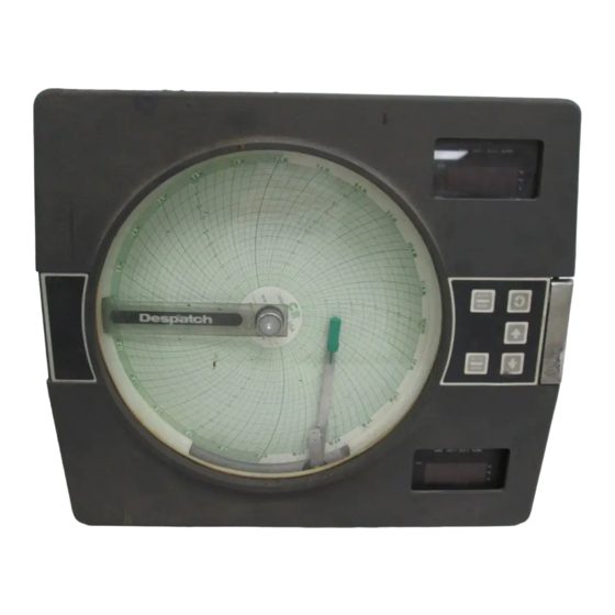
Product Description 1.1 1.1.1 GENERAL The instrument is a microprocessor based circular chart Recorder Controller capable of measuring, displaying, recording and controlling from a variety of inputs. Applications include temperature, level, pressure, flow and others. The instruments can be specified as either a single or as a dual pen model. - Page 6 1.1.2 RECORDING The instrument records the selected process variable on a 10-inch circular chart. One box of standard charts is provided with each recorder. Charts are available in a wide selection of ranges. Chart rotation speed is programmable from 0.1 to 999.9 hours per revolution in 0.1 hour increments.
- Page 7 1.1.7 DIGITAL COMMUNICATIONS The instrument can be ordered with a Digital Communications option that provides the capability of bi-directional communications with a supervisory computer. A dual pen instrument can have an individual address selected for each pen. Refer to the Communica- tions Protocol Manual (Form 2878) for more details regarding the communications option.
-
Page 8: Installation & Wiring
Installation and Wiring 2.1 Read these instructions carefully before proceeding with installation and operation. Electrical code requirements and safety standards should be observed. Installation should be performed by qualified personnel. CAUTION: The Instrument AC power input is specified in the model number and on the wiring label affixed to the the top center of the platen. -
Page 9: Preparation For Wiring
FIGURE 2-1 7/8" Dia hole for wiring - 3 locations, EC1, EC2, and EC3 13 3 (335 mm) PLACES 3 3 4 (64 mm) 15 1 (384.2 mm) WIDTH OF COVER (119.1 mm) 2 19 (65.9 mm) Mounting Bracket (2) 32 DIA.(7.1mm) Holes to mount bracket to surface... - Page 10 3. A separate isolation transformer to feed only instrumentation should be considered. The transformer can isolate the instrument from noise found on the AC power input. 4. If the instrument is being installed on existing equipment, the wiring in the area should be checked to insure that good wiring practices have been followed.
- Page 11 FIGURE 2-2 1000V Coil ohms 115V 1/4W 230V 1W FIGURE 2-3 Inductive Load GlobalTestSupply www. .com Find Quality Products Online at: sales@GlobalTestSupply.com...
- Page 12 2.5.2 SENSOR PLACEMENT (THERMOCOUPLE OR RTD) If the temperature probe is to be subjected to corrosive or abrasive conditions, it should be protected by the appropriate thermowell. The probe should be positioned to reflect true process temperature: In liquid media - the mose agitated area. In air - the best circulated area.
- Page 13 RTD LEAD RESISTANCE RTD lead length can affect instrument accuracy. Size (gauge) and length of the wire used affects lead length resistance. To determine the temperature error resulting from the lead length resistance, use the following equation: Terr = TLe * L where;...
-
Page 14: Wiring Connections 2.6
Wiring Connections 2.6 All wiring connections are typically made to the instrument at the time of installation. Connec- tions are made at the terminal boards provided, two 12 gauge wires maximum. Terminal boards are designated TB1 through TB13. See Figure 2-4 for the terminal board locations. The number of terminal boards present on the instrument depend upon the model number/ hardware configuration. -
Page 15: Figure 2-6 Thermocouple Inputs
FIGURE 2-5 AC Instrument Power Input Connect the 115 VAC hot and neutral to terminals 1 and 2 respectively of TB1. See Figure 2-4 (page 14) for Terminal Board locations on the instrument. Connect the 230 VAC one leg to each terminal, be sure to check the position of the Voltage Selector switch provided with 230 VAC instruments. -
Page 16: Figure 2-9 Remote Setpoint Input Vdc, Madc
FIGURE 2-8 Volt, Millivolt and milliamp Input Make the volt, millivolt and milliamp connections as shown below. Use TB4 for thePen 1 input, and TB5 for the Pen 2 input. Terminal 1 is positive and terminal 2 is negative. The milliamp input requires the installation of an appropriate shunt resistor (ordered separately) between terminals 1 and 2. -
Page 17: Figure 2-10 Digital Communications
FIGURE 2-10 Digital Communications Options Connections are made as shown using TB2. Refer to the Protocol Manual, Form #2878 for more details regarding the connections and how to use this option. This document is provided only when this option has been specified. If the communications network continues on to other instruments, connect the cable shields together, but not to the instrument. -
Page 18: Figure 2-11B Spdt Relay Output
FIGURE 2-11B SPDT Relay Output POWER LOAD 5 AMPERES 1 2 3 MAXIMUM AT 115 VAC N.O. C N.C. TB6 Relay A TB7 Relay B FIGURE 2-12 SSR Driver Output Connections are made to relays H through A as shown. Terminal connections are made using TB9, TB8, etc. -
Page 19: Figure 2-15 Position Proportioning Control Output
FIGURE 2-14 Transmitter Power Supply Input If the isolated 24 VDC regulated transmitter power supply has been specified, the connections should be made as shown. Connections are made using TB3, terminal 1 is positive and terminal 2 is negative. The power supply is capable of providing the power needed by up to 2 transducers (40 mADC maximum). -
Page 20: Section 3 - Configuration
Configuration 3.1 After completing installation and wiring of the instrument the configuration (set up) procedures must be performed to prepare the instrument for operation on the intended application. The procedures include selecting specific parameters, entering data and possible jumper position- ing. -
Page 21: Configuration/Jumper Positioning
Shipped Configuration/Jumper Positioning 3.2 Each instrument is factory shipped ready to accept a thermocouple input on TB 4 and TB 5. All parameters in each mode are set to default values. These defaults are shown in tabular form after the description for each mode. Instrument AC power input is as specified in the instrument model number and is shown on the ratings label. -
Page 22: Front Panel Operation 3.5
3.4.1 POWER UP PROCEDURE Step 1 Verify that all electrical connections have been properly made before applying power to instrument. Step 2A - For instruments with software revision R2.99 and below Upon power up, 7XXX will be displayed (X representing digits), then XXXX, then XXXX, identifying the twelve digit model number as defined in the order matrix. - Page 23 3.5.2 KEYPAD CONTROLS The keys on the keypad functions include: SCROLL: Used to : 1. Display the enabled modes. 2. While in a mode, used to sequence the parameter codes and values. 3. Exit some Test and Calibration functions 4. Work in conjunction with other keys: a.
- Page 24 FIGURE 3-1 Pen 1 SCROLL AUTO/MAN Pen 2 DOWN AUTO/MAN LAMP TEST From the Off or Control modes, all display and status LEDs can be illuminated simultaneously by depressing the UP and DOWN keys at the same time. Any defective LEDs will not light. CHANGE CHART (also see Changing Charts, Section 5.2) If the UP and DOWN keys are held depressed for more than 2 seconds but less than 4 seconds, the display will show CChg momentarily.
- Page 25 PROGRAM MODE FLOW CHART Prog inPS diSP iCor dPoS out1 o1uL o1LL out2 HyCo HyAo o2uL o2LL Actual Display rSPu On/Off Display - Use arrow keys to turn on or off Scroll Key Numeric Display - Use arrow keys to change value Up Arrow Key Down Arrow GlobalTestSupply...
- Page 26 rSPL SPuL SPLL AtFr P1EC P2EC Prnd PAEC rLyA Actual Display rLyb Pout On/Off Display - Use arrow keys to turn on or off rLyC Scroll Key Numeric Display - Use arrow keys to change value Up Arrow Key Down Arrow GlobalTestSupply www.
- Page 27 rLyd Cobr rLyE CoCr rLyF Codr rLyg PAPu rLyH CurA Com (Optional) CCon Curb CurC Curd CAd1 CoAr CAd2 GlobalTestSupply www. .com Find Quality Products Online at: sales@GlobalTestSupply.com...
-
Page 28: Table 3-1 Program Mode Configuration Procedure
TABLE 3-1 PROGRAM MODE CONFIGURATION PROCEDURE Press the SCROLL key until Prog is displayed. Press the DOWN key to enter the Program mode. Pen 1 will be displayed in the upper display. To enter the Pen 1 parameter, press the DOWN key. - Page 29 DISPLAY AVAILABLE FACTORY YOUR STEP DESCRIPTION CODES SETTINGS SETTING SETTING Output 1 Percent o1uL 0 to 100 percent Upper Limit (o1uLand o1LL will not be seen if out1 = 0,1,2) Output 1 Percent o1LL 0 to 100 percent Lower Limit Output 2 out2 0 = None (Position...
- Page 30 DISPLAY AVAILABLE FACTORY YOUR STEP DESCRIPTION CODES SETTINGS SETTING SETTING Hysteresis for HyAo 0 to 300 Alarm Outputs Width of Hysteresis Band (see page 66 for definition) Remote Setpoint 0 to 2 If rSP is set to zero 0=Not Used then rSPu and rSPL 1=1 to 5 VDC are not seen...
- Page 31 DISPLAY AVAILABLE FACTORY YOUR STEP DESCRIPTION CODES SETTINGS SETTING SETTING Pen Action on PAEC 0 or 1 Error Condition 0 = Pen goes to 0 % of chart 1 = Pen goes to 100 % of chart Pressing the SCROLL key with the PAEC parameter value displayed in the Pen 1 window will advance the display of a single pen instrument to the unit parameters.
- Page 32 DISPLAY AVAILABLE FACTORY YOUR STEP DESCRIPTION CODES SETTINGS SETTING SETTING Current Output B Cobr Same selection as CoAr Range Current Output C CoCr Same selection as CoAr Range Current Output D Codr Same selection as CoAr Range Chart Rotation Time 0.1 to 999.9 hours per rotation Pen Action on Power Up...
- Page 33 TUNE MODE FLOW CHART tunE rSEt PAL1 ArSt dAL1 rAtE bAL1 PAL2 SEnS dAL2 bAL2 Actual Display On/Off Display - Use arrow keys to turn on or off Scroll Key Numeric Display - Use arrow keys to change value Up Arrow Key Down Arrow GlobalTestSupply www.
-
Page 34: Table 3-2 Tune Mode Configuration Procedure
TABLE 3-2 TUNE MODE CONFIGURATION PROCEDURE The Tune mode allows the entry, review or altering of the process control Tune adjustments and alarm setting(s). To enter the Tune mode, press and release the SCROLL key until tunE is displayed, then press the DOWN key. - Page 35 DISPLAY AVAILABLE FACTORY YOUR STEP DESCRIPTION CODES SETTINGS SETTING SETTING Automatic Reset ArSt 0.0 to 100.0 repeats Integration per minute (Will be seen if Pb1 or Pb2 was shown) Rate Derivative rAtE 0.0 to 10.0 minutes (Wll be seen if Pb1 or Pb2 was seen) Cycle Time Output 1 1 to 240 seconds...
-
Page 36: Table 3-3 Enable Mode Configuration Procedure
TABLE 3-3 ENABLE MODE CONFIGURATION PROCEDURE To enter the Enable mode, press the UP and DOWN keys while in CtrL or oFF modes. All the display lamps will light. After 2 seconds, the display will show Cchg and the pen(s) will move to and remain at a point above the top graduation on the chart. -
Page 37: Section 4 - Operation
Operation 4.1 4.1.1 OFF MODE In the Off mode, the instrument control and alarm function (s) are turned off. Process Retransmission signal(s) remain active. The chart rotation can be selected in the Program mode to stop or continue to rotate when the instrument is in the Off mode. The pen(s) will remain active. - Page 38 Dual Pen Instruments: If the instrument is specified and provided with the Remote Setpoint capability for either or both pens and the Remote Setpoint has been properly configured in the Program mode for either or both pens, the Setpoint Select mode will be accessible, if enabled. Press and release the SCROLL keys until SPS appears in the display, then press the DOWN key.
- Page 39 4.1.2.4 TIME PROPORTIONING CONTROL Time Proportioning Control can be implemented on controllers provided with SPST relay or SSR driver output(s). Time proportioning can be programed for output 1 and/or 2 for each pen. Time proportioning control is accomplished by cycling the output On and Off when the process value is within the proportional bandwidth selected at a prescribed time period.
- Page 40 4.1.2.7 PROPORTIONAL OUTPUT PERCENTAGE DISPLAY While in the Control mode, pressing the UP and the SCROLL keys at the same time will cause the display to sequence through a series of display codes and values: Percent Output (if applicable) Output 1% value Percent Output (if applicable) Output 2% value Proc...
-
Page 41: Alarm Operation 4.2
STANDBY MODE FLOW CHART Stby Actual Display On/Off Display - Use arrow keys to turn on or off Scroll Key Numeric Display - Use arrow keys to change value Up Arrow Key Down Arrow Alarm Operation 4.2 There are two alarms available per pen. The type of alarm is selected in the Program mode as follows: 1. -
Page 42: Tune Mode Operation 4.3
Tune Mode Operation 4.3 Proportional output controllers may require the adjustment (tuning) of the PID and other related parameters. This provides a means for the instrument's control algorithm to be adjusted to meet specific application requirements. 4.3.1 SYSTEMATIC TUNING METHOD 1. - Page 43 4.3.2 ZIEGLER NICHOLS TUNING METHOD This procedure has been determined empirically to yield ideal 1/4 amptitude decay tuning parameters that are determined by watching the system in a sustained oscillation (curve C, page 44, the ultimate proportional band and ultimate time period) and then using these values from this sustained oscillation to calculate ideal parameters.
- Page 44 Period Curve A : unstable Curve B : stable Curve C : continuously cycling, ultimate PB and period GlobalTestSupply www. .com Find Quality Products Online at: sales@GlobalTestSupply.com...
-
Page 45: Service 5.1
Service 5.1 This section contains information regarding calibration and test procedures that can be performed in the field as well as items concerning the normal maintenance of the instrument. Changing Charts Chart changes may be done while in the normal operating mode. CAUTION: The chart flange assembly pin is sharp to perforate the chart. -
Page 46: Calibration 5.4
Calibration 5.4 CAUTION: Do not attempt any calibrations without the proper test equipment that meets or exceeds the specifications listed. Press and release the SCROLL key until CAL appears on the display , then press the DOWN key to enter the mode. The display will change to CAL1. Press the SCROLL key to advance the display to the other calibration modes available. -
Page 47: Table 5-1 Calibration Procedure
TABLE 5-1 CALIBRATION PROCEDURES Calibration Procedure Description CAL 1 Reinitialization of program and tuning values. CAL 2 Main calibration necessary for all input types. CAL 3 Cold Junction Compensation calibration used to correct for component variation in the CJC circuit. Necessary for thermocouple inputs. CAL 4 Cold Junction Utility, displays temperature the cold junction compensator is sensing. - Page 48 Error recovery: See section 5.6 (page 55) for details. Ensure that the millivolt source is connected correctly and functioning properly. The calibration can be exited when hLd1 or the calibration reference number is displayed by pressing the SCROLL key. CAL2 QUICK CALIBRATION This routine will allow the operator to execute a rough calibration on their unit via the keypad with no other equipment or disturbance to established wiring.
- Page 49 5.4.5 CAL 5 RTD INPUT This procedure determines and saves calibration values relating to RTD inputs. This calibra- tion must be preceded by CAL 2 to properly calibrate the instrument. Both RTD inputs must be calibrated and both inputs must have valid inputs during the calibration. Decade boxes with .01% resolution or equivalent are required.
- Page 50 5.4.7 CAL 9 PEN CALIBRATION This procedure is used to calibrate the pen(s). No special test equipment required. Valid inputs must be connected to TB 4 and TB 5 before performing this calibration. With CAL 9 displayed, push and hold the DOWN key, then press the SCROLL key . Release both keys and the display will indicate PEn1.
-
Page 51: Test Mode Procedures
Test Mode 5.5 To enter the Test mode, press and release the SCROLL key until tESt appears on the display then press the DOWN key. tSt1 will be displayed, press and release the SCROLL key to advance the display to the desired test. Tests 1, 2 and 3 are performed as a unit so the display will advance directly to tSt4 from tSt1. -
Page 52: Table 5-2 Test Procedures And Description
TABLE 5-2 TEST PROCEDURES AND DESCRIPTION Test Description Test 1 Microprocessor internal RAM test. Used to check the processor RAM to make sure it is functioning correctly. Test 2 External RAM test, used to test the RAM chip for proper function. Test 3 EPROM checksum test, used to check that the EPROM program is correct. - Page 53 5.5.5 TEST 5 KEYPAD/DISPLAY TEST This test allows the operator to verify that the keys work and that all display elements can be lighted. No special test equipment is required. With tSt5 displayed, press and hold the DOWN key, then press the SCROLL key and then release both keys.
- Page 54 The current output reading should be ± 0.1 mADC at any output value. A ± 5 % of span adjustment for the current output(s) is provided by using the potentiometer adjacent to the current output on the Current Output board. See Appendix A-4 (page 65). To exit the test, press the SCROLL key and tSt7 will be displayed.
-
Page 55: Troubleshooting And Diagnostics (Error Code Definitions)
Trouble-shooting and Diagnostics 5.6 The Trouble-shooting Guidelines Section consists of two columns. The first column is a list of some possible instrument conditions. The second column is a list of steps that should improve the condition. The steps should be performed in order until the condition improves or all the steps have been completed. - Page 56 Model Number Displayed 1. Turn off the instrument power, wait 5 seconds then during power up is re-apply the power. Verify that the number displayed incorrect during the power up sequence is the same as indicated on the label affixed to the platen. If the number displayed is incorrect, perform the following steps: a.
- Page 57 5. If the output appears not to turn off remove the power to the instrument. Open the cover and loosen the platen hold down screw. Swing the platen open. Clip the resistor located on the Relay Board adjacent to the output(s) that seem to stay on (See Appendix A-2, page 63).
- Page 58 4. For software revision R2.99 and below, perform Test 9 as described in the Test Section of the manual (page 54). If the pen feedback voltage does not vary, check the pen Potentiometer Segment board for proper ribbon cable connection to the Processor board (Appendix A-1, page 62) and that the pen position fingers are making contact with Potentiometer Segment board.
- Page 59 3. If this error appears, check the Program mode parameter dPos, if not 0, change to 0 and see if the error clears. Er 1 - Microprocessor RAM 1. Turn off the power to the instrument. Wait 5 seconds, Failure and turn the power on.
- Page 60 Er 9 - ADC Reference 1. Perform the CAL2 procedure as described in the Number Error Calibration section (page 47). Er10 - ADC Reference 1. Perform the CAL2 procedure as described in the Voltage Error Calibration section (page 47). Er11 - Cold Junction 1.
- Page 61 Er36 - Incorrect Crystal 1. Turn off the power to the instrument, wait 5 seconds, For Digital Comm. then turn the power on. Er37 - Incorrect Micro. 1. Turn off the power to the instrument wait 5 seconds, For Digital Comm. then turn the power on.
-
Page 62: Processor Board
Appendix A Board Layouts FIGURE A-1 - PROCESSOR BOARD SWI for Rev. Y and above SWI for Rev. X and below ENABLE MODE UNLOCKED LOCKED EPROM SIZE 230/115 VAC SWITCH 230 VAC MODEL ONLY JU4 PEN 1 INPUT T/C,mV, RTD VOLT/mA JU5 PEN 2 INPUT (REVERSE OF JU4) -
Page 63: Spst Relay/Ssr Driver Output Board
FIGURE A-2 - SPST RELAY/SSR DRIVER OUTPUT BOARD TS1 R1 TS5 R5 TS6 R6 (rlyE) (rlyF) (rlyC) (rlyD) (rlyB) (rlyA) (rlyH) (rlyG) Resistor Relay If the relay is connected to a Relay A high impedance AC device, Relay B the snubber network used to Relay C protect the relay contact may Relay D... -
Page 64: Spdt Relay/Ssr Driver Output Baord
FIGURE A-3 - SPDT RELAY/SSR DRIVER OUTPUT BOARD TS1 R1 TS5 R5 TS6 R6 (rlyA) (rlyB) (rlyC) (rlyD) (rlyH) (rlyG) Resistor Relay If the relay is connected to a R1, R2 Relay A high impedance AC device, R3, R4 Relay B the snubber network used to Relay C protect the relay contact may... -
Page 65: Current Output Board
FIGURE A-4 - CURRENT OUTPUT BOARD TB13 TB12 TB10 TB11 If this option board was ordered, you will find it located in the lower right hand corner of the instrument. GlobalTestSupply www. .com Find Quality Products Online at: sales@GlobalTestSupply.com... -
Page 66: B - Glossary
Appendix B Glossary Automatic Reset (Integral) This parameter is used so that the instrument will compensate for process variable deviations from setpoint that occur when the process load characteristics change. Instructions for determining the automatic reset settings are given in Table 3-2 (Page 34). Factory default is.0.0. - Page 67 Pen Action on Power Up This parameter specifies whether the pen, on a power-up will drive to the "Home Position" (center of chart), then return to its correct postion. This is done as a cal check. Settings are 0=go to "home" and 1=remain in last position prior to power down. Default is 0. Platen The flat surface in the instrument upon which the chart rotates.
-
Page 68: C- Order Matrix
Appendix C Order Matrix Option Suffix Pen 1 00 None 2 Recording Controller N3 - NEMA3† Pen 2 Voltage 0 None 1 115VAC Input 1 Recorder Only 2 115/230VAC Input 2 Recorder Controller CSA Approved *Relay (SPST) Outputs 4 115VAC Input 0 None 5 115/230VAC Input 1 One... -
Page 69: D- Product Specifications
Appendix D Product Specifications Measurement Error Limit • Type J,K,T,E,N,C T/C’s and RTD +/-0.25% of reading plus 1 degree @ 25 degrees C • Type R,S, B T/C’s +/-0.25% of span @ 25 degrees C • mA, mV and VDC +/-0.25% of scaled span plus 1 Whole Digit @ 25 degrees C Ambient Temperature Error 0.01% of span per degree C deviation from 25 degrees C... - Page 70 Input Specifications THERMOCOUPLE TYPE RANGE TYPE RANGE 0 to 760C 0 to 750C 0 to 1400F 0 to 1400F 0 to 1360C 200 to 1800C 0 to 2500F 400 to 3300F -220 to 400C 0 to 1300C -330 to 750F 0 to 2370F 200 to 1650C 200 to 2300C...
- Page 71 ALARM ADJUSTMENTS Process Alarm -9999 to 9999 units Deviation Alarm -3000 to 3000 units Deviation Band Alarm 1 to 3000 units Hysteresis 0 to 300 units CONTROL OUTPUTS Relay SPST 115 VAC: 5.0A Resistive, 1/8HP or 250VA 230 VAC: 2.5A Resistive, 1/8HP or 250VA SSR Driver Open collector output Short circuit protected @ 100mA maximum...
-
Page 72: E- Software Record/Reference Sheet
Appendix E Software Reference/Record Sheet PROGRAM MODE TUNE MODE Pen 1 Pen 2 unit Pen 1 Pen 2 inPS rLyA iCor PAL1 rLyb out1 rLyC dAL1 o1uL bAL1 rLyd o1LL rLyE PAL2 out2 dAL2 rLyF o2uL bAL2 rLyg o2LL rLyh CurA Curb rSEt... - Page 73 These products are warranted to be free from functional defects in materials and workman- ship at the time the products leave The Partlow-West Company factory and to conform at that time to the specifications set forth in the relevant Partlow-West instruction manual or manuals, sheet or sheets, for such products for a period of three years.
Need help?
Do you have a question about the MRC 7000 and is the answer not in the manual?
Questions and answers