
Related Manuals for JRC jue-87

Summary of Contents for JRC jue-87
- Page 1 JUE-87 JUE-87 INMARSAT-C INMARSAT-C MOBILE EARTH STATION MOBILE EARTH STATION INSTRUCTION INSTRUCTION MANUAL MANUAL...
- Page 3 ABOUT YOUR SAFETY CAUTIONS AGAINST HIGH VOLTAGE Radio and radar devices are operated by high voltages of anywhere from a few hundred volts up to many hundreds of thousands of volts. Although there is no danger with normal use, it is very dangerous if contact is made with the internal parts of these devices.
- Page 4 FIRST AID ☆Note points for first aid Unless there is impending danger leave the victim where he or she is, then begin artificial respiration. Once you begin artificial respiration, you must continue without losing rhythm. (1) Make contacts with the victim cautiously, there is a risk that you may get electrocuted. (2) Switch off the machinery and then move the victim away slowly if you must.
- Page 5 ☆ If the victim has a pulse but is not breathing (“Mouth to mouth” resuscitation) (1) Place the victim’s head facing backward (place something under the neck like a pillow). (2) Point the chin upward to widen the trachea. (3) Pinch the victim’s nose, take a deep breath, then put your mouth over the victim’s mouth and exhale completely, making sure that your mouth completely covers the victim’s mouth.
- Page 6 ☆ If the victim has no pulse and is not breathing (Heart massage in combination with artificial respiration.) If the victim has no pulse, his or her pupils are dilated, and if you cannot detect a heartbeat, the heart may have stopped, beginning artificial respiration is critical.
- Page 7 PREFACE Thank you for purchase of the JRC Inmarsat-C, Mobile Earth Station, JUE-87. • Please read this manual carefully and carry out proper operation. • Please keep this manual importantly to refer to when it is necessary. Please use it when questions and troubles are caused in operation, by any chance.
-
Page 8: Attentions Before Installation
ATTENTIONS BEFORE INSTALLATION • JRC cannot accept responsibility for any loss due to incorrect operation, malfunction, and other causes except product guarantee condition and liability by law. • There is possibility that some functions of the terminal may not operate correctly depend on the hardware and software version of equipment connected to the terminal. -
Page 9: Before Installation
BEFORE INSTALLATION About safety symbols This manual and the terminal are indicated the following safety symbols for your correct operation to prevent your and somebody’s injury or damage to the product and assets. The symbols and descriptions are as follows. You should understand well them before reading this manual and operating the terminal. -
Page 10: About Warning Labels
ABOUT WARNING LABELS Below mentioned warning labels are put on JUE-87. Do not take off, destroy, or modify these labels. Labels put on EME Labels put on IME <Type1>... - Page 11 <Type2>...
- Page 12 Immediately after printing, the printing head is still very hot, don’t touch it until it is cool down. WARNING Do not bring JUE-87 (EME) close to the fire, or put it in the fire. It causes the explosion, generation of heat. Do not approach the JUE-87 (EME) while transmitting, It transmits microwave and strong microwave might be cause injury.
- Page 13 CAUTIONS TO BE USED DURING OPERATION CAUTION Before operating JUE-87, read the operation manual carefully. Inappropriate procedure may cause incorrect operation or malfunction. When a failure has been detected, check it according to the Trouble shooting described in this book. If abnormalities are still accepted, restart the terminal. Nevertheless abnormalities are still accepted, stop operation and contact the dealer or agent from which you purchased the device or one of our branches, marketing offices, and representative offices.
-
Page 14: Distress Alert Transmission Procedures
0.5 sec ON immediately release the 1.0 sec OFF. button within 4 sec. • Distress alert is transmitted • The buzzer sounds • When the JUE-87 is tuning after continuously pressing continuously. to LES channel, the SYNC • IME displays “Distress DISTRESS button for 4 sec LED blinks. -
Page 15: Acronyms And Abbreviations
ACRONYMS AND ABBREVIATIONS AC ......................Alternating Current ACK ......................Acknowledgement AFC..................Automatic Frequency Control AGC....................Automatic Gain Control ALM ..........................Alarm AMVER..........Automated Mutual-assistance Vessel Rescue system A vessel position-reporting system operated by the United States Coast Guard for any merchant vessel of 1000grt or more on a voyage lasting longer than 24 hours, to and from anywhere on the world. - Page 16 BS ..........................Backspace Bulletin Board (in a TDM channel): A data packet transmitted in each frame of a TDM channel, which contains information about the status of the Inmarsat B/M, mini-M and C network configurations, and the current frame number, used by the MES as a timing reference. BUZ ..........................
- Page 17 CUG ......................Closed User Group Private network used by the registered user only. Unregistered user cannot be accessed from public network. Data reporting: A short data packet transmitted in burst mode on the MES signaling channel as a result of a polling telecommand or at the initiative of the MES (operator). Data services: This is how a terminal may send and receive electronic messages such as e-mail.
- Page 18 EGC...................... Enhanced Group Call The system for broadcasting messages via Inmarsat C mobile satellite communications system that supports two services: SafetyNET and FleetNET. EIA ..................Electronic Industries Association EIRP..............Equivalent Isotropically Radiated Power Effective Isotropically Radiated Power, a measure of transmitted power. E-mail......................
- Page 19 IA5 ..................International Alphabet number 5 A standard alpha- numeric character set, also known as ASCII, based on 7-bit codes. Supports both upper and lower case characters. ID ..........................Identity IF.......................Intermediate Frequency IFU................... Intermediate Frequency Unit IHO ..............International Hydrographic Organization IME..................
- Page 20 LES TDM channel: A TDM channel used by an LES to transmit system information and data addressed to an MES. LMSS ..................Land Mobile Satellite Service Log in: The action performed on an Inmarsat C MES to inform the NCS in an ocean region that the MES is available for communications.
- Page 21 NAVAREA....................Navigational Area A geographical sea area established for the purpose of co ordinating the broadcast of navigational warnings. NAVTEX ...............MF Navigational Broadcast Service The system for The broadcast and automatic reception of Maritime Safety information by means of narrow-band direct-printing telegraphy. NCS..................
- Page 22 PSTN ................Public Switched Telephone Network PSU......................Power Supply Unit PVT ..................Performance Verification Test RAM....................Random Access Memory RCC...................Rescue Coordination Center RDB ....................Remote Distress Button REC ........................Receiving level ROM......................Read Only Memory RX......................... Receive/Receiver SafetyNET The international service for the broadcasting and automatic reception of MSI through Inmarsat EGC system.
- Page 23 TDM channel: The Inmarsat system uses different TDM channels, each transmitted on an unique frequency. The TDM channels are used for system control and message transfer to MESs. See LES TDM Channel and NCS Common Channel. Time slot: Basic unit into which one time frame of a TDM channel is divided. TX ......................Transmit/Transmitter User defined area A temporary geographic area, either circular or rectangular, to which maritime safety...
- Page 24 xviii...
-
Page 25: Table Of Contents
ACRONYMS AND ABBREVIATIONS ....................ix CHAPTER 1. GENERAL ........................1-1 CHAPTER 2. COMPOSITION......................2-1 2.1 JUE-87 Installation Wiring Diagram, Components and Supplied Parts List........ 2-1 2.1.1 Installation Wiring Diagram ...................... 2-1 2.1.2 Components List........................2-4 2.1.3 Supplied Parts by JRC....................... 2-5 2.1.4 Parts for Installation (Prepared by Shipyard) ................ - Page 26 3.3 Log Out............................3-3 3.4 Main Menu Screen ........................3-4 3.4.1 Command ..........................3-5 3.4.2 MES Status Area........................3-8 3.4.3 Menu Structure Chart ........................ 3-9 3.4.4 Additional Menu Structure Chart .................... 3-10 3.5 Initial Setting ..........................3-11 3.5.1 Selecting Preferred Ocean Region (Ncs/Les info) ..............3-11 3.5.2 Setting Date &...
- Page 27 4.3.1 WARNING Window........................ 4-12 4.3.2 CAUTION Window ........................ 4-13 4.3.3 ERROR Window ........................4-14 4.3.4 MES INFORMATION Window....................4-16 4.4 Help Function ..........................4-19 CHAPTER 5. Specification........................5-1 5.1 JUE-87............................5-1 5.1.1 EME (NAF-253GM) and IME (NTF-318)................5-1 5.1.2 Printer (NKG-800) ........................5-2...
- Page 28 INMARSAT SYSTEM COVERAGE AREAS............A1-1 APPENDIX 2. WHAT IS LRIT? ....................A2-1 APPENDIX 3. TELEX DESTINATION CODES LIST ..............A3-1 APPENDIX 4. INTERNATIONAL TELEPHONE CODES LIST ........... A4-1 APPENDIX 5. NKG-800 PRINTER INSTALLATION GUIDE ............A5-1 APPENDIX 6. JRC SERVICE NETWORK ..................A6-1...
-
Page 29: Chapter 1. General
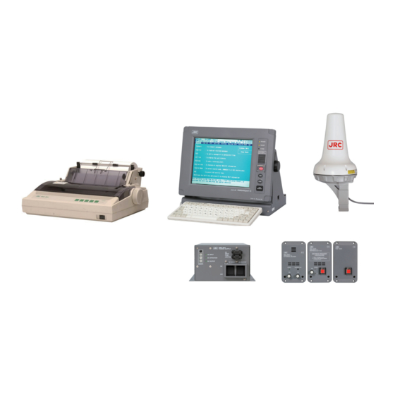
CHAPTER 1. GENERAL This manual covers the installation, operation, and maintenance of the MES (Mobile Earth Station) JUE-87 for Inmarsat-C satellite communications. The Inmarsat-C satellite communications provides text and data transmission to and from Inmarsat-C MES and terrestrial subscribers via a variety of public networks. It also carries the EGC (Enhanced Group Call) message. -
Page 31: Chapter 2. Composition
CHAPTER 2. COMPOSITION 2.1 JUE-87 Installation Wiring Diagram, Components and Supplied Parts List 2.1.1 Installation Wiring Diagram The following diagram is for stand alone mounting type. Fig.2.1.1a Wiring Diagram Inmarsat-C JUE-87 Mobile Earth Station (Stand alone, JB1) - Page 32 The following diagram is GMDSS console mounting type. Fig.2.1.1b Wiring Diagram Inmarsat-C JUE-87 Mobile Earth Station (GM console, JB1)
- Page 33 Fig.2.1.1b Installation Wiring Diagram Inmarsat-C JUE-87 Mobile Earth Station (2/2) Fig. 2.1.2 Wiring Diagram Inmarsat-C JUE-87 Mobile Earth Station (JB2)
-
Page 34: Components List
EXT BUZ (External Buzzer) NCE-5547 1 to 3 NQE-3223 JUE-87 SSAS Option Instruction Manual 7ZPSC0450 JUE-87 SSAS Option Operation Guide 7ZPSC0452 * “Standard components” means the needful units for Inmarsat-C Mobile Earth Station. * Use the cable [250V TTYCS-4] to connect IME and remote Distress button. -
Page 35: Supplied Parts By Jrc
2.1.3 Supplied Parts by JRC Table 2.1.3a Supplied parts by JRC for EME Installation Name Type Q’ty Remarks Application Single unit by Fixing Band MPBP31867 Painting Protection Material MPXP33556 “SUMI” Tape (Self Bandaging Tape) BRXP05369 Packing List MTZ304557 Table 2.1.3b Supplied parts by JRC for IME Installation... -
Page 36: Parts For Installation (Prepared By Shipyard)
Table 2.1.3d Supplied Cables by JRC for IME Installation Name Type Q’ty Remarks Application EXT PSU Cable (IME to EXT PSU) 7ZCSC0320 Printer Signal Cable 7ZCSC0321 (Printer to IME) Printer Power Cable 7ZCSC0322 (Printer to IME) JB1 Cable (JB1 to IME) 7ZCSC0314 0.4m... -
Page 37: Consumable Supplies And Spare Parts List
2.1.6 Consumable Supplies and Spare Parts List Table 2.1.6a Consumable Supplies List Name Type Remarks Application Size: Roll paper 5ZPAL00002 Recording paper (1PLY) 214mmW 98mmφ Roll paper Size: 5ZPCK00001 Recording paper (2PLY) 214mmW 124mmφ Print head unit 5ZYWZ00001 Ink ribbon 5ZZCM00003 Color: Black Table 2.1.6b Spare Parts List (H-7ZXSC8701) -
Page 38: Standard Components)
2.2 JUE-87 (Standard Components) 2.2.1 EME (Externally Mounted Equipment: NAF-253GM) EME is connected to IME with a coaxial cable. The cable can be extended to maximum 100 m. Fig.2.2.1 EME... -
Page 39: Ime (Internally Mounted Equipment: Ntf-318)
2.2.2 IME (Internally Mounted Equipment: NTF-318) IME is consists of Interface Unit, Power Supply Unit, Process Circuit, Color LCD Unit, I/F Circuit and USB I/F Circuit. POWER LED Display READY LED COMM LED Distress BUTTON Screen Angle Adjust Knob Dimmer BUTTON Power SWITCH USB PORT Keyboard... - Page 40 Fig.2.2.2b Back View of IME Table 2.2.2c Connectors and the Cable (Refer to Fig.2.2.2b) Name Connected from/to (1) LAN Port PC or HUB for RMS (2) KEYBOARD Port KEYBOARD (3) SERIAL Port (Not USED) (4) DTE Port (5) JB2 Port (6) PRINTER Port PRINTER (7) JB1 Port...
-
Page 41: Printer (Nkg-800)
• When status is off line: received message is not printed. • Use a roll-paper (JRC code :5ZPAL00002 for one-sheet copy and 5ZPCK00001for two-sheet copy) and ink ribbon (5ZZCM00003) Do not use except above mentioned products, for keep normal operation. -
Page 42: Ext Psu (External Power Supply Unit: Nbd-904)
2.2.4 EXT PSU (External Power supply Unit: NBD-904) The EXT PSU (NBD-904) supplies DC+24V for IME-EME and Printer from Ship’s power source (from 100 to 240V AC) and/or +24V DC. When both AC and DC power source are connected to the EXT PSU and the power interruption of AC power source is occurred: EXT PSU switches over from AC power source to the DC power source automatically (Power failure detecting function). -
Page 43: Coaxial Cable (Cfq-5922A)
2.2.6 Coaxial Cable (CFQ-5922A) Connecting EME and Antenna Cable. Fig.2.2.7 Coaxial Cable 2-13... -
Page 44: Appearance (Optional Components)
2.3 Appearance (Optional Components) 2.3.1 RDB (Remote Distress Button: NQE-3225) The DB (Distress Button ) is used to transmitting Distress Alert. (1)Distress Button (With cover) (3) DIMMER (2) READY Lamp Fig.2.3.1 Remote Distress Button (1) Distress Button Used to Distress Alert transmission. In case of transmitting Distress Alert, open hinged cover and press the button for 4 seconds. -
Page 45: Jb2 (Junction Box 2: Nqe-3223)
2.3.2 JB2 (Junction Box 2: NQE-3223) It is used when two or more RDB or EXT BUZ is installed. Fig.2.3.2 JB2 2-15... -
Page 46: Dte (Data Terminal Equipment: Display Ndz-227 And Keyboard Ndf-369)
2.3.3 DTE (Data Terminal Equipment: Display NDZ-227 and Keyboard NDF-369) DTE is composed of display and keyboard, and is connected to IME. DTE can be connected to USB drive. CAUTION Do not use the DTE to other purpose. It may cause a problem that unable to be transmitted in the emergency. NOTE •... -
Page 47: Ext Buz (External Buzzer: Nce-5547)
(2)BUZ OFF Switch (5)Volume (4)DIMMER Fig.2.3.4 EXT BUZ (1) Buzzer Sounds when JUE-87 receives messages (INM-C and EGC) (2) BUZ OFF Switch Used to stop the buzzer sounding by pressing the switch. (3) POWER LED Illuminates when power is supplied. -
Page 48: Dimensional Drawing (Jue-87 Standard Components)
2.4 Dimensional Drawing (JUE-87 Standard Components) 2.4.1 EME (NAF-253GM) Unit: Mass 2.4 kg Color: N9 Fig.2.4.1 EME 2-18... -
Page 49: Ime (Ntf-318)
2.4.2 IME (NTF-318) Fig.2.4.2 IME 2-19... -
Page 50: Dte Keyboard (Ndf-369)
2.4.3 DTE Keyboard (NDF-369) Unit : mm Mass : 0.4kg Fig.2.4.3 DTE Keyboard 2-20... -
Page 51: Printer (Nkg-800)
2.4.4 Printer (NKG-800) Unit: mm Fixing Mass: 3.7kg Attach the hook and loop fastener to the bottom of the printer and the desk, and then fix them. Fig.2.4.4 Printer 2-21... -
Page 52: Ext Psu (Nbd-904)
2.4.5 EXT PSU (NBD-904) Serial Number Seal DimmerVolume x 3 Mount Hole Fuse x 2 4-φ6x8 Refer to Table5.1.5 Principal Specification of EXT PSU for detailed specifications. Unit: mm Mass: 2.6kg Fig.2.4.5 EXT PSU 2-22... -
Page 53: Jb1 (Nqe-3222)
2.4.6 JB1 (NQE-3222) Fig.2.4.6 JB1 2-23... -
Page 54: Coaxial Cable (Cfq-5922A)
2.4.7 Coaxial Cable (CFQ-5922A) Connecting EME and Antenna Cable. Max.22mm Max.8mm Minimum bending radius: 46mm Type Length Standard: CFQ-5922A3 30m(±10cm) Option: CFQ-5922A4 40m(±10cm) Option: CFQ-5922A5 50m(±10cm) Fig.2.4.7 Coaxial Cable 2-24... -
Page 55: Dimensional Drawing (Optional Components)
2.5 Dimensional Drawing (Optional Components) 2.5.1 RDB (NQE-3225) Fig.2.5.1 Remote Distress Button 2-25... -
Page 56: Jb2 (Nqe-3223)
2.5.2 JB2 (NQE-3223) Fig.2.5.2 JB2 2-26... -
Page 57: Dte (Display Ndz-227 Keyboard Ndf-369)
2.5.3 DTE (Display NDZ-227 Keyboard NDF-369) Fig.2.5.3 DTE 2-27... -
Page 58: Ext Buz (Nce-5547)
2.5.4 EXT BUZ (NCE-5547) Fig.2.5.4 EXT BUZ 2-28... -
Page 59: Sb (Security Button: Nqe-3224)
2.5.6 SB (Security Button: NQE-3224) Fig.2.5.6 Security Button 2-29... - Page 60 2-30...
-
Page 61: Chapter 3. Operation
* Log-in: It is to notice initiating operation of JUE-87 to NCS (Network Coordination Station), which is operated automatically when power switch is turned on. * Log-out: It is to notice ending operation of JUE-87 to NCS, which is operated automatically when power switch is turned off. -
Page 62: Power On
3.1.1 Power ON Before turning on all power switches of JUE-87, confirm that all the signal cables and power cables are connected correctly. Step Operation/Response (Example) Screen (Example) • Turn on the DC switch and AC switch on the NOW LOADING・・・... -
Page 63: Log In
3.2 Log In When the status in the first line on the main menu is “Log-out” or “Egc only”, initiate the “Log-in” according to the following procedures; When the “Receive mode” is changed from “Egc receive only” to “Inmarsat-C”. The “Log-In” is initiated automatically. -
Page 64: Main Menu Screen
3.4 Main Menu Screen The JUE-87 operation adopts a multi-level menu structure with window-menus and hierarchical - submenus. Refer to clause 3.4.3 and 3.4.4 for confirming the composition of each menu. All the time, screen displays the newest information by pop-up window. - Page 65 3.4.1 Command JUE-87 has two kinds of way to operate the IME/DTE, one is selecting command by cursor, and the other one is pressing the buttons directory. Direct commands make quicker and easy operation when you get used to the operation of IME/DTE.
- Page 66 ..set Up • To set the current date & time; • To initiate a Log-out, Log-in or performance test; • To register each parameter for scheduled transmission; • To register land ID for polling; • To select the closed network ID; •...
- Page 67 (3) Screen control commands You can control screen on the IME/DTE by pressing one of the following keys while holding down key: Ctrl ..To light up the display backlight and LED to 15 stages Ctrl ↑ ..To darken the display backlight and LED to 15 stages Ctrl ↓...
- Page 68 3.4.2 MES Status Area Fig.3.4.2 MES Status Area...
-
Page 69: Menu Structure Chart
3.4.3 Menu Structure Chart Fig.3.4.3 Menu Structure Chart... -
Page 70: Additional Menu Structure Chart
3.4.4 Additional Menu Structure Chart To display additional menu, hold down the key and press key on main menu. (Additional menu screen) Additional Menu Status Displays MES status set Up Sets MES parameter diAgnostics Diagnoses MES To display the Status screen, press and hold key and then press key in the main menu or additional menu. -
Page 71: Initial Setting
3.5 Initial Setting After turn on the JUE-87 MES, set the following parameters; (1) Selecting Preferred Ocean Region (2) Setting Date & Time (3) Setting Peripheral Function 3.5.1 Selecting Preferred Ocean Region (Ncs/Les info) When a particular ocean region is selected, the MES will scan the NCS common channel only in the ocean region selected. -
Page 72: Setting Date & Time
When the Date & time (displayed in the bottom line on the right side of the first screen) is wrong, correct the Date & time as follows. When the JUE-87 is synchronized with the NCS common channel, the time is reset at 00:00 (UTC) everyday by Inmarsat frame channel. -
Page 73: Setting Peripheral Function
3.5.3 Setting Peripheral Function Set the peripheral device (printer, data port, navigation equipment, and/or buzzer) function. Setting procedure is as follows; Step Operation IME/DTE Response Remarks • • The “Set up” window Hold down key and press key on Main menu. is displayed. - Page 74 Fig.3.5.4 “DTE message type” Window • Nav. equipment connected with MES: * Choose the port connected with MES and interface condition, i.e. Nmea0183, nMea0182 or JRC original, when you choose “Internal”. * Choose interface from “Nmea0183” or “nMea0182” when you choose “External”. (as usual, select “Nmea0183”)
- Page 75 • dAta port #1 (LAN port): Set parameters of Local Area Network. - IP Address (Default Primary IP: 192.168.60.247, Secondary IP: 192.168.60.248) - Subnet mask - Default gateway - Jcmail port number • daTa port #2 (IME optional DTE port (option)): Set the data port which is connected.
-
Page 76: Ime/Dte Display Setting (Config)
3.6 IME/DTE Display Setting (Config) This menu can set the IME display setting. Config LCD/LED dimmer LCD/LED dimmer (0-15) : 13 LCD/LED dimmer button LCD/LED dimmer button setting Screensaver setting Screen saver function - Function ON/OFF : ON - Starting time (1-15) : 3 minutes Display color pattern : Ocean Day... -
Page 77: Screensaver Setting
Step Operation IME/DTE Response ・ Move the cursor to setting “LCD/LED ・The cursor is move to next step. dimmer button setting” with using the arrow keys and press key. Enter ・Move the cursor to the following three ・The cursor is move to the setting area. step, you want to change (Maximum, Typical or Minimum) and press Enter key. -
Page 78: Display Color Pattern
3.6.4 Display Color Pattern This menu can set the display color pattern and select from the following 9 colors. Ocean Day, Ocean Dusk, Ocean Night,Earth Day, Earth Dusk, Earth Night, Basic Black, Basic White, and User defined. When select the User defined, the color pattern is set “3.6.5 User defined color setting” Step Operation IME/DTE Response... -
Page 79: Background Color Of Main Display
3.6.5.1 Background Color of Main Display This menu can set Main area background color. Step Operation IME/DTE Response ・Move the cursor to “Background color ・“Background color of main display” of main display” with using the arrow setting window is displayed. keys and press Enter key. -
Page 80: Shortcut Character Color
3.6.5.5 Shortcut Character Color This menu can set capital character shows shortcut command. Step Operation IME/DTE Response ・Move the cursor to “Shortcut character ・“Shortcut character color” setting window color” with using the arrow keys and is displayed. press Enter key. ・Select the color and press Enter key. - Page 81 NOTE When saves the file at the 101th, the following window is displayed. In this case, delete the unnecessary file until the file number is decreased less than 100, by “delete file” command. This window is continuously displayed until the file number is decreased less than 100. ERROR Can not create new file.
- Page 82 In “edit telex file” mode; Note 1) The characters which can use on the land telex line can be input. So, the following characters and the small letters are rejected in the file: !, @, #, $, %, ^, &, *, _, {, [, ], }, :, ¥, ;, ”, ~, ’, and - Note 2) Edit telex file uses the extension “.TLX”...
-
Page 83: Editing Menu
3.7.1.1 Editing Menu “Edit” has two sets of the function-key commands, group A and group B. Each command set can be selected alternately by pressing (“-Others-”) key. Group A Function Step Operation Example (“Insert-on”) Move the cursor to the character to THE QUCK BROWN •... - Page 84 Function Step Operation Example (“Quit”) Press (“Quit”). • Exit Edit without Saving When “Really quit without • File saving? No” is displayed, select “Yes” for finishing the editing without saving or “No” for returning the editing to save the file. (“Save As”) Press to save the edited file as...
- Page 85 Group B Function Step Operation Example (“Max Column”) Press (“Max Column”). Input Max Column • Number of characters per Numbers:_ Line Type the number of characters per • (Note) line and press Enter key. (“Set Tab”) Press (“Set Tab”). Input Column Numbers:_ •...
- Page 86 Function Step Operation Example • (“Find/Replace”) 1. THE QUICK Move the cursor to the Word Search and Replace beginning of the line. 2. THE BLOCK 3. THE QUICK • Input Search String: Press (“Find/Replace”). • Input Replace String: Input the search string and press Enter EX.
-
Page 87: Block Function
3.7.1.2 Block Function When the block is selected in Edit mode previously, the block can be copied, moved, deleted and etc. The block function menu is provided on Edit mode. Item of the menu is as follows: Top-marker of block Bottom-marker of block rEmove markers Copy block... - Page 88 (2) Copy block Step Operation Example 1. THE QUICK Select the Block according to • 2. THE QUICK the item (1) “Select Block”. 3. THE QUICK 4. THE QUICK 1. THE QUICK Move the cursor to the character • 2. THE QUICK where the block is to be inserted.
- Page 89 (5) Save block Step Operation Example 1. THE QUICK Select the Block according to • 2. THE QUICK the item (1) “Select Block”. 3. THE QUICK Press (“Block”). File name:_ • Select “Save block as” and • press key. Enter Enter the file name to be saved File name: ABC.
-
Page 90: File Management
3.7.2 File Management The edited message file in the IME/DTE memory can be deleted, renamed, or copied by the file management menu. When the USB drive is connected to the IME/DTE optionally, the edited message file in the USB drive can be deleted, renamed, or copied by the file management menu. Delete file : To delete a file Rename file :... - Page 91 (2) Rename file Step Operation IME/DTE Response Remarks Move the cursor to “Edit” “Edit” window is displayed. • • and press key. Enter Select “reName file” and The file list memorized in IME/DTE • • press key. and “Current file name: ” is Enter displayed.
-
Page 92: Usb Drive Management Menu
When the USB Device is not connected, please close the rubber flap in order to maintain • waterproofing and dust-proofing. JRC can not accept responsibility for any loss due to use virus-infected USB Device except product • guarantee condition and liability by law. - Page 93 NOTE When the source file name is presented to the target USB drive, “WARNING, File XXXX. XXX(file name) already present on the USB drive, Do you want to overwrite it? No” is displayed. When the file name is overwritten, select and press key.
-
Page 94: Usb Drive Feature Overview
3.7.3.3 USB Drive Feature Overview (1) USB drive compatibility ※1: The USB device must be USB Flash memory. ※2: The USB Flash memory complies with USB 1.1 or USB 2.0 standards. ※3: The USB Flash memory has NOT any built-in USB hubs. ※4: The USB Flash memory has NOT any security functions. - Page 95 ※8: The maximum name length of folders and files which are accessible by the IME/DTE is 255 characters in full path. ※9: The USB Flash memory which contains multibyte character filenames and folders which can be created under other than the IME/DTE must not connect. ※10: The rubber cap on the USB connector of the IME/DTE must be closed when a USB Flash memory is not connected.
-
Page 96: Transmitting Message (Transmit)
Fig.3.8a “Transmit” Window NOTE The size of the transmission message in JUE-87 is 8000 bytes maximum. If the size of the message is exceeded 8000 bytes, the following windows is displayed. In this case, reduce the size to 8000 bytes or less divide the message to a few file. -
Page 97: Sending Telex
3.8.1 Sending Telex NOTE • DO NOT REQUEST ANY DISTRESS PRIORITY CALLS EXCEPT IN AN EMERGENCY. Accident alarm message is transmitted to Rescue Coordination Center regardless of destination code, subscriber’s number, and answerback. • Distress telex message is retransmitted after the device is restarted, when momentary disconnection is occurred in the device during the distress telex message transmitting. - Page 98 Step Operation IME/DTE Response Remarks • • Move the cursor to “Transmit” and The “Transmit” press key. window is displayed. Enter • • • Move the cursor to “Telex” and The “Telex” window “Telex” is the press key. is displayed. mandatory facility Enter for all LESs.
- Page 99 Enter LES ID directly. • • • Confirm the contents and press The “Les list” When the JUE-87 is (“LES list”) key. window is displayed. not synchronized to satellite, the blank list is displayed. • • •...
- Page 100 Step Operation IME/DTE Response Remarks • • • After confirmation of each The contents of the Normally, it takes parameter, press (“Send Call”) selected file are about 3-5 minutes displayed, and then to complete the key. Main menu is communication. displayed again.
- Page 101 Note 3) When the selected LED ID is closed, or the selected LES ID is other than 000~063, 100~ 163, 200~263, and 300~363, the following window is displayed. Press (“Previous”) key and type the correct LES ID. ERROR Selected LES does not operate in this ocean. Confirm the LES ID.
-
Page 102: Transmitting E-Mail Message
3.8.2 Transmitting E-mail Message Special access network Special access code : 28 File name : TEST.MSG land Earth station(les) : 203 (Yamaguchi) posItion : Off characTer code : Data delivery Confirmation : Off F1: Send call F10: Previous Fig.3.8.2a Example of “E-mail” Window Step Operation IME/DTE Response... - Page 103 Enter LES ID directly. “land Earth station (les)”. . • • • Press (“Les list”) key. The “Les list” window When the JUE-87 is is displayed. not synchronized to satellite, the blank list is displayed. • • • ↑ ↓...
- Page 104 Step Operation IME/DTE Response Remarks • • Main menu is displayed. Press (“Previous”) key to return to main menu. Note 1) When the entered file name is not in the IME/DTE memory or the USB drive, “ERROR, The file is missing. Confirm the file name.” is displayed, press (“Previous”) key and type the new file name.
-
Page 105: Transmitting Facsimile Message
3.8.3 Transmitting Facsimile Message Facsimile country coDe- subscriber’s number : 081-422459957 Modem of subscriber : T30 File name : TEST.MSG land Earth station(les) : 203 (Yamaguchi) posItion : Off characTer code : Ia5 delivery Confirmation : Off F1: Send call F10: Previous Fig.3.8.3a Example of “Facsimile”... - Page 106 LES Enter ID directly. • Press (“LES list”) • The “LES list” window is • When the JUE-87 is not contents and press displayed. synchronized to satellite, (“Previous”) key. the blank list is displayed. ↑...
- Page 107 Step Operation IME/DTE Response Remarks • When the delivery The cursor is return • confirmation is requested to to ”country LES, select “oN” and press coDe-subscriber’s key. number”. Enter • When the delivery confirmation is not requested to LES, select “Off” and press key.
- Page 108 Note 1) Message can be sent to up to 5 subscribers whom destination code is same, by moving the cursor to “Destination code-subscriber’s number and answerback code” then pressing Enter key (Multi address function). When the subscriber’s number set to two numbers or more, “*” is displayed at right side of the number.
-
Page 109: Transmitting Data (Psdn) Message
3.8.4 Transmitting Data (PSDN) Message Data(PSDN) Data network id subscriber’s number : 1117-422459957 File name : TEST.MSG land Earth station(les) : 203 (Yamaguchi) posItion : Off delivery Confirmation : Off F1: Send call F10: Previous Fig.3.8.4a “Data (PSDN)” Window Step Operation IME/DTE Response Remarks... - Page 110 LES Enter ID directly. • • • Press (“LES list”) key. The “Les list” window is When the JUE-87 is not synchronized to satellite, displayed. the blank list is displayed. • Note 4 • • Select the LES ID by ↑...
- Page 111 Step Operation IME/DTE Response Remarks • • • Confirm each parameter The Main menu is Normally, it takes about and press (“Send Call”) displayed. 3-5 minutes to complete key. the communication. • • “S&F message (96-01-15 Press (“previous”) 11:00) sent to LES key to clear the (203)”...
-
Page 112: Transmitting Data (Pstn) Message
Note 3) Following window is displayed when you carry out the procedure of Step 9. Press (“Previous”) key when you carry out data transmission. Warning Can not display binary text. F10:Previous Fig.3.8.4c “WARNING” Window Note 4) When the selected LED ID is closed, or the selected LES ID is other than 000~063, 100~163, 200~263, and 300~363, the following window is displayed. - Page 113 Step Operation IME/DTE Response Remarks • • Move the cursor to The “Transmit” window is “Transmit” and press displayed. key. Enter • • • Move the cursor to the The “Data (PSTN)” “Data (PSTN)” is “data (psTn)” and press optional facility for window is displayed.
- Page 114 Enter LES ID directly. • Press • The “LES list” window is • When the JUE-87 is not (“LES list”) key. displayed. synchronized to satellite, the blank list is displayed. • Select the LES ID by •...
- Page 115 Step Operation IME/DTE Response Remarks • When the delivery • The cursor is returned to confirmation is requested to “country coDe-subscriber’s LES, select “oN” and press number”. key. Enter • When the delivery confirmation is not requested to LES, select “Off”...
- Page 116 Note 2) When the file is not in the IME/DTE memory or the USB drive, the following window is displayed, press (“Previous”) key and type the new file name. ERROR The file is missing. Confirm the file name. F10: Previous Fig.3.8.5b “ERROR”...
-
Page 117: Transmitting Closed Network Message
3.8.6 Transmitting Closed Network Message NOTE It is necessary to download the closed network ID (DNID) from LES prior to the closed network message is transmitted. Closed network (dnid) cloSed network id (dnid) : 12345 File name : TEST.MSG land Earth station (les) : 203 (Yamaguchi) posItion : Off... - Page 118 “land Enter LES ID directly. Earth station (les)”. • • • The “LES list” window is When the JUE-87 is not Press (“LES list”) key. displayed. synchronized to satellite, the blank list is displayed. • •...
- Page 119 Step Operation IME/DTE Response Remarks • • When the setting of the The cursor is moved to “posItion” is changed, right column from press key. “posItion”. Enter • • When the ship’s position is The cursor is moved to included the transmitting “traNsfer”.
- Page 120 Note 1) When the entered file name is not in the IME/DTE memory or the USB drive, “ERROR, The file is missing. Confirm the file name.” is displayed. Then press (“Previous”) key and type the new file name. ERROR The file is missing. Confirm the file name.
-
Page 121: Transmitting Special Access Network Message
3.8.7 Transmitting Special Access Network Message Special access network Special access code : 28 File name : TEST.MSG land Earth station(les) : 203 (Yamaguchi) posItion : Off characTer code : Data delivery Confirmation : Off F1: Send call F10: Previous Fig.3.8.7a Example of “Special access network”... - Page 122 LES ID directly. “land Earth station (les)”. . • • • Press (“Les list”) key. The “Les list” window When the JUE-87 is is displayed. not synchronized to satellite, the blank list is displayed. • • • Select the LES ID by ↑...
- Page 123 Step Operation IME/DTE Response Remarks • • Main menu is displayed. Press (“Previous”) key to return to main menu. Note 1) When the entered file name is not in the IME/DTE memory or the USB drive, “ERROR, The file is missing. Confirm the file name.” is displayed, press (“Previous”) key and type the new file name.
-
Page 124: Address Book
3.8.8 Address Book (1) Address number registration Step Operation IME/DTE Response Remarks • • Move the cursor to The “Transmit” “Transmit” and press window is displayed. key. Enter • The address number can • • Move the cursor to the The “Transmit”... - Page 125 (2) Address number selection Step Operation IME/DTE Response Remarks • • Move the cursor to The “Transmit” window “Transmit” and press is displayed. key, on main menu. Enter • • Move the cursor to the Selected service window is service type to register the displayed.
-
Page 126: Scheduled Transmission
3.8.9 Scheduled Transmission JUE-87 can send position information, file, and/or data from data source to a designated party in regular interval. Up to 5 schedules can be registered. Step Operation IME/DTE Response Remarks Hold down key and press The “Set up” window is key on Main menu. - Page 127 • Starting date and time Set the date and time you want to start for a scheduled transmission. • Requesting interval Set the interval time of schedule. (Minimum 10 minutes) • LES Set the LES IDs you want to use, in all ocean regions. The first field is West AOR (000-063), the second field is East AOR (100-163), the third field is POR (200-263) and the fourth field is IOR (300-363).
- Page 128 • File (File name) Set the file name you want to send. Confirmation of file name is required at “Edit”. Message with no file name is sent when unrecorded file name is inputted. • Transmission Choose the schedule on or off. 3-68...
-
Page 129: Handling Received Messages (Read-Out, Printing, Saving, And Deleting)
100 calls, or 40K bytes. When your JUE-87 stored over 90 calls, warning window is displayed (Fig.3.9g). If the numbers of calls exceed 100, the call logs are deleted from older ones. When you need to read out, print out, saving, or deleting the messages, follow the below procedures. - Page 130 Inm-C message list No. Date Time Priority Size 1. 05-01-01 01:12 Routine 1000 2. 04-12-02 01:10 Routine 1001 3. 04-11-30 01:33 Routine 1002 4. 04-10-22 01:41 Routine 1003 5. 04-09-20 01:55 Routine 1004 6. 04-05-30 01:22 Routine 1005 7. 03-12-24 01:08 Routine 1006 8.
- Page 131 Reception message list No. Date Time Priority Size Service 1. 05-01-01 01:12 Safety 1000 *Group call 2. 04-12-02 01:10 Routine 1001 3. 04-11-30 01:33 Urgent 1002 *INMARSAT system message 4. 04-10-22 01:41 Routine 1003 5. 04-09-20 01:55 Safety 1004 * 6.
- Page 132 (2) To delete the message Step Operation IME/DTE Response Remarks • • • Move the cursor to “Read-out” window is “Inm-C”: “read Out” and press displayed. It shows three “Inm-C message list” types of message list. key. Enter “Egc” : “Egc message list”...
- Page 133 EGC Message list (Delete) No. Date Time Priority Size Service 1. 05-01-01 01:12 Routine 1000 Group call 2. 04-12-02 01:10 Safety 1001 Urgency message, NAV warning 3. 04-11-30 01:33 Urgent 1002 INMARSAT system message 4. 04-10-22 01:41 Distress 1003 Coastal warning 5.
-
Page 134: Call Logging (Call-Log)
3.10 Call Logging (Call-Log) Call history of the latest calls (up to 100) are stored in the IME memory, and are displayed by moving the cursor to “call-Log” and pressing key, in the main menu. Enter If the numbers of calls exceed 100, the call logs are deleted from older ones and waning window (Fig.3.9g) is displayed. - Page 135 Note: (1) “Time” area (example: 14:20-14:25) shows the starting time and stopping time of the call. (2) “Type of call” shows the communication type and the direction as follows: • Type of call S&F: Store & Forward communication (Telex communication) S&F Poll: Automatic response communication with S&F to the polling command S&F sched:...
-
Page 136: Delivery Confirmation
3.10.1 Delivery Confirmation When you want to confirm the delivery result of the transmitted message, press (“Delivery confirmation”) key of the “Call logging history” window (see previous page), then select the message to be confirmed on “Delivery confirmation request window”, then press key. - Page 137 Delivery confirmation request to has a experience of executing Delivery selected call for the first time. confirmation request in the past. JUE-87 asks about the JUE-87 only displays Information of information of delivery delivery confirmation stored in its confirmation to LES. memory.
-
Page 138: Print Out
S&F message (96-04-14-08: 10) delivered to subscribers (072123456, 0729876543). F10: Previous Fig.3.10.1d Example of “Delivery confirmation” Window for A Message Sent to A Subscriber. Delivery confirmation Date Time Type of call Destination Msg no Size 05-04-8 14:20 S&F 00123123456789012 12345678 12345 : Call failure –... -
Page 139: Buzzer (Alarm) Processing
Turn off the IME when you cannot stop the sound by pressing Ctrl + A . Contact the JRC service agent and let them know about Alarm history of your JUE-87, when some sort of failure is occurred. (See 4.2. “Troubleshooting”.) -
Page 140: Distress Alert (Distress)
3.11 Distress Alert (Distress) NOTE • DO NOT SEND DISTRESS ALERT EXCEPT YOU ARE IN GRAVE AND IMMINENT DANGER • Update content of the distress alert prior to its transmission. • Distress alert can be transmitted from dedicated distress button only. Distress alert Nature : Undesignated... - Page 141 Step Operation IME/DTE Response Remarks • • Move the cursor to “Distress” and press “Distress Alert” key. window is displayed. Enter • • Move the cursor to “Nature of distress” “Nature of distress” window is displayed. and press key. Enter Nature of distress Undesignated fire/Explosion...
- Page 142 • • • “LES list” window When the Press F2 ( “LES list” ) key. screen is displayed. JUE-87 is not synchronized to satellite, the blank list is displayed. • • ↑ ↓ Choose LES ID using key and “Distress alert”...
-
Page 143: Polling
3.12 Polling Polling is the function, which is automatically sending position of JUE-87, file or data, demanded from land Telex users. JUE-87 provides the following polling function from land telex user; • Position polling by using S&F message transfer •... - Page 144 Land ID registration for polling # 1 Destination code & subscriber’s no : 072-02822351 LES: 002-111-210-312 # 2 Destination code & subscriber’s no : LES: 0 -1 -2 -3 # 3 Destination code & subscriber’s no : LES: 0 -1 -2 -3 # 4 Destination code &...
-
Page 145: Position Polling Using S&F Message Transfer
Land user can poll the MES’s position information by S&F message transfer. When the following text is included in the received message, JUE-87 checks the land ID then transmit the MES’s position information to the land user in the text if the number is registered. -
Page 146: File Polling By Using S&F Message Transfer
Land user can access to the MES’s file on IME/DTE’s memory by S&F message transfer. When the following text is included in the received message, JUE-87 checks the land ID, then transmit the contents of file or its list to the land user in the text if the user’s number is registered. - Page 147 Command for file list polling /FLISTX/XXX:XXX..XXX/X..X/ Network type [TELEX, PSDN or Vxx (for PSTN)] Subscriber’s number (up to 11-digit) Destination code (3-digit) Port number of DTE connected (1-digit) 0: Data port main 2: Data port #2 (Option) Example of file list polling MES receives the following message: /FLIST0/072:02822351/TELEX/ NNNN...
-
Page 148: Data Source Polling By Using S&F Message Transfer
Land user can access to the data from data source connected with MES by S&F message transfer. When the following text is included in the received message, JUE-87 checks the land ID then transmit the data from data source to the land user in the text if the number is registered. The maximum data size is up to 2K bytes per each port. -
Page 149: Parameter Setting Polling For Scheduled Transmission
3.12.5 Parameter Setting Polling for Scheduled Transmission Parameters of scheduled transmission are changeable from IME/DTE or the polling from land based user. Firstly, land based user should read out the parameters with parameter read out command. Land user will acquire the access code and parameters. The access code is changed by each command of reading out and is required to change the parameters. - Page 150 Command for parameter setting /SP/XXXXXX/X/XXXXXX/XXXX/XXXX/XXX/X..X/XXX:X...X/X..X/X..X/X.X/ Transmission LES ID [ON or OFF] Data type [DS0, DS1, Interval [HHMM] DS2, P or combination] Start time [HHMM] Presentation [IA5, ITA2 or DATA] Start date [YYMMDD] Subscriber’s number Schedule number Destination code [4-digit for PSDN Access code 3-digit for TELEX and PSTN] Destination code (3-digit)
-
Page 151: Call Log By Using S&F Message Transfer
3.12.6 Call Log by Using S&F Message Transfer Land user will read out the latest up 10 call log from MES by S&F message transfer. When the following command is included in the polled message, the MES checks the land ID then transmit MES’s call log to the land based user in the number is registered in the land ID registration for polling. -
Page 152: Egc Message Reception
EGC is a message broadcast service within the Inmarsat-C communication system. It allows terrestrial information providers to pass messages or data to JUE-87 Inmarsat-C MES. EGC messages are sent to Land Earth Station by shore based Information Providers using terrestrial facilities such as Telex, and are processed at the LES, and forwarded to an NCS then are broadcasted to the INMARSA-C MES via NCS common channel transmitted by NCS. -
Page 153: Receive Mode For Egc Reception (Receive-Mode)
3.13.3 EGC Message Restriction (Egc) The JUE-87 can restrict to EGC message reception with Navarea, Fixed area, reception type, Satellite Coastal areas, and Coastal Warning type. Choose “egC” on main menu to setup this function. Also JUE-87 has the function that printing EGC message automatically when received it. See “3.13.3.7”, when you want to stop it. -
Page 154: Setting Of Navarea/Metarea
3.13.3.1 Setting of Navarea/Metarea Only receives the messages to Navarea/Metarea, which have been set up. NOTE Basically, information of Navarea/Metarea in the ocean region being logged in now is sent. Step Operation IME/DTE Response Remarks • • Move the cursor to “egC” The “EGC”... - Page 155 Fig.3.13.3.1b Navarea/Metarea 3-95...
-
Page 156: Setting Of Fixed Area
3.13.3.2 Setting of Fixed Area Step Operation IME/DTE Response Remarks • • Move the cursor to “egC” The “EGC” window is and press key. displayed. Enter • • When you want to change The cursor is moved to the fixed area, move the the “Fixed area”... - Page 157 EGC reception type charT correction service : Enable Chart correction service for fixed areas: Enable Download group identity (ENID) : Enable General call (All ships) : Enable group calL (Fleet NET) : Enable F10: Previous Fig.3.13.3.3 “EGC reception type” Window Step Operation IME/DTE Response...
-
Page 158: Setting Of Satellite Coastal Areas
3.13.3.4 Setting of Satellite Coastal Areas The JUE-87 can restrict the Satellite Coastal Area message of the A through Z areas. Choose the area you want to receive or restrict from these areas. Satellite coastal areas A: Enable N: Enable... -
Page 159: Setting Of Coastal Warning Type
3.13.3.5 Setting of Coastal Warning Type The JUE-87 can restrict the Coastal Warnings mentioned below. other Electronic navaid messages Pilot and VTS service messages ・ ・ ・ Ice reports ・ GNSS messages Loran messages no message on Hand ・ ・... - Page 160 Step Operation IME/DTE Response Remarks • • Move the cursor to “egC” The “EGC” window is and press key. displayed. Enter • • Move the cursor to The “Coastal worning “coastal Warning type” type” window is and press key. displayed. Enter •...
-
Page 161: Position Updated
Safety NET message with priorities higher than routine are received. Note 2) When any GPS equipment is connected with the JUE-87, ship’s position data is updated automatically. If GPS equipment is disconnected more than 3 minutes, it sounds and displays warning. -
Page 162: Message Print Out Function
And DTE displays warning message and sounds. 3.13.3.7 Message Print Out Function When the JUE-87 is received the EGC or Inmarsat-C message, the received message is printed out automatically that is the message print out function. When this function is turned off or on according to the following procedure. -
Page 163: Pv Test
3.14 PV Test Performance Verification Test of JUE-87 can be carried out with following below outlined procedures. Carry out PV test with confirming that JUE-87 is logged-in. Step Operation IME/DTE Response Remarks • • Hold down key and The “Set up” window is displayed. - Page 164 The Distress button test can be demonstrated the procedure of a distress alert transmission even if the JUE-87 is not synchronized to satellite. NOTE To avoid sending the false distress alert transmission, confirm certainly that JUE-87 is in the test mode, prior to carrying out Distress button test. 3-104...
- Page 165 Step Operation IME/DTE Response • • “Diagnostics” window is displayed. Hold down key and press key on Main Menu. Diagnostics Data source contents Alarm history software Version distress button Test F10: Previous • • Move the cursor to “distress button “Distress Button test mode”...
-
Page 166: Distress Button Test
Step Operation IME/DTE Response • • To start the distress test, press the The buzzers in DTE and IME are sounding 5 distress button again. sec continuously. • The “DISTRESS” lamp on IME is illuminating 5 sec. --- Distress Button Test --- Distress button test succeeded. -
Page 167: Data Reporting Function
3.16 Data Reporting Function 3.16.1 Data Reporting Function Overview The data reporting function has two type methods of reporting, or immediate reporting and periodic reporting. The data reporting function mainly is used as MES’s periodic position reporting. There are three type function, or DR (Data Reporting), EDR (Enhanced Data Reporting), EPADR (Enhanced Pre-assigned Data Reporting) as the data reporting function. -
Page 168: Comparison Of Various Data Reporting Function
3.16.2 Comparison of Various Data Reporting Function The comparison of DR, EDR and EPADR function is as follows. EPADR Previously assigned channel and slot* Confirm acknowledgement Re-sent report after reporting failure Request program/assignment from MES Maximum of data size 32 bytes 40 bytes 40 bytes * If channel and slot does not previously assigned, packet collision may occur. - Page 169 (3) EPADR communication sequence The MES sends a data report to the LES by the channel and the slot which are previously assigned. Pre-assigned channel and slot (a) When EPADR transmission is successful, EPADR communication sequence is completed. (b) When EPADR transmission is failed, the MES re-sends data report to the LES by EDR communication sequence.
-
Page 170: Confirmation Of Dnid
3.16.3 Confirmation of DNID DNID can be confirmed by following procedure. Step Operation IME/DTE response • • Hold down Alt key and press U "Set up" window is displayed. key on Main menu. Set up Date & time confiG log-Out initiation log-In initiation Performance test initiation Scheduled transmission... -
Page 171: Confirmation Of Polling Program
3.16.4 Confirmation of Polling Program Polling Program can be confirmed by following procedure. Step Operation IME/DTE response • • Hold down Alt key and press U "Set up" window is displayed. key on Main menu. • • Move the cursor to "dnid "DNID Selection"... -
Page 172: Epadr
3.16.5 EPADR 3.16.5.1 Confirmation of EPADR Assignment EPADR Assignment can be confirmed by following procedure. Step Operation IME/DTE response • • Hold down Alt key and press U "Set up" window is displayed. key on Main menu. Set up Date & time confiG log-Out initiation log-In initiation... - Page 173 EPADR Assignment #1 destination Address type : SLCN & DNID : 003 (KDDI JPN) Dnid/mem : 12345/100 (ABCDEFGHIJKLMNOPQRSTUVWXY) transmission Interval : 2 hours number of Packets : 2 packets number of Reports : 7000 Number of Reports remaining : 6999 Status of the assignment : Active Start Date&Time (YY-MM-DD hh:mm)
-
Page 174: Request Of Epadr Assignment
Multi-user detection (MUD) • LES TDM/Sig CH/Slot: The channel information will be used on EPADR transmission. 3.16.5.2 Request of EPADR Assignment EPADR Assignment can be requested from JUE-87 by following procedure. However, the request may be rejected. Step Operation IME/DTE response •... - Page 175 Step Operation IME/DTE response • • Press F1 key. The following warning message is displayed. Warning EPADR Assignment #1 Request OK? Cancel F10 Previous • Move the cursor to "OK" and press Enter key. Note 1) If you want to request changing parameter of previously downloaded assignment, please display EPADR Assignment window of the assignment.
-
Page 176: Setting Of Epadr Transmission Data
3.16.5.3 Setting of EPADR Transmission Data EPADR transmission data can be set by following procedure. However, there is a possibility that trouble of operation using EPADR occur by setting of EPADR transmission data. Step Operation IME/DTE response • • Hold down Alt key and press U "Set up"... -
Page 177: Call Logging For Epadr
3.16.5.4 Call Logging for EPADR When EPADR Assignment is accessed, downloaded, suspended or resumed, the result for the access is recorded instead of Msg no in “Msg no” field of call logging (refer to section 3.10). When the access is accepted, “Accept” is recorded in Msg no field. When the access is rejected, “Reject”... - Page 178 3-118...
-
Page 179: Chapter 4. Maintenance
CHAPTER 4. MAINTENANCE 4.1 Maintenance Keep the equipment in a good state according to the following maintenance. 4.1.1 Daily Maintenance 4.1.1.1 Mechanical Maintenance 1) Cleaning Keep the equipment as clean as possible. In particular, wipe the ventilation opening with a dry cloth. 2) Tightening of screws Check screws in all parts of the equipment and tighten any loosen one. -
Page 180: Troubleshooting
Check all items in the following section to secure normal communication at all times. When any unusual phenomenon occurs in the equipment, send appropriate information to JRC service network to get advice or to request for repair with the results of these items. - Page 181 From previous page Is Ready lamp lit Is ID registered? after 2 minutes? Application Does Buzzer sound during operation? (EME internal Exchange GPS error) Is not the alarm Contact JRC recorded? Completed Fig4.2.1b Troubleshooting Flowchart (2/2)
-
Page 182: Alarm Check
Various operation states and alarm states are displayed on the first line of the screen of IME/DTE and alarm history is displayed as the following procedure. 4.2.3 Alarm History The JUE-87 has a self-monitoring function named alarm history, which is displayed as the following procedure: Step... - Page 183 Table 4.2.3 Contents of Alarm history Display format Content (In case of Fig.4.2.3) IMN:4XXXXXXXX MES Number ① (IMN:410032123) SER:XXXXXX ② Serial Number (SER:068577) EME Board Version (XX) HW:XX/Y ③ (HW:01/4) IME Board Version (Y) ACSE Main Version (XX.XX) ACSE:XX.XX/Y.Y ④ (ACSE:01.00/2.0) ACSE SAFE Mode Version (Y.Y) MDM:XX.XX...
- Page 184 Receiver AGC setting value (UU) shows the gain control value to adjust level of current receiving signal. Normal value : from 80(hex) to E0 (Hex) Lower value shows that receiving signal is stronger and receiver circuit performance is better. Receiving C/N0 (VVVV) shows 10 times C/No dBHz. This value depends on both received signal from satellite and receiver circuit performances.
- Page 185 No alarm (If there are any alarm, 0x000000 Add the following each status value) EME ROM data alarm + 0x800000 EME RAM data alarm <Note> + 0x400000 If user stops power supply without “Log-out”, this bit becomes “high”. + 0x200000 EEPROM data alarm EEPROM FATAL alarm + 0x100000...
- Page 186 “MD2” values are fixed for each terminal. They show transmitter hardware set value in factory. If MD2 values is all zeros or all “F”, JUE-87 can not transmit normally. In that case, contact the JRC service agent and let us know about Alarm history of your JUE-87.
-
Page 187: Countermeasure
4.2.4 Countermeasure If the equipment does not operate in normal even after the following procedure is performed, consult JRC service agent. Take care not to touch any parts on PC board. Abnormal operation of IME/DTE In case of the heavy fluctuation of the voltage or frequency of the power source, or thunderbolt and etc., IME may not operate normally. -
Page 188: After Service
Disposal of JUE-87 When disposing JUE-87 process it in accordance with the rules of the pertinent local government. For details, contact to the purchasing dealer from which you purchased, our service office or a pertinent local government. -
Page 189: Pop-Up Window
4.3 Pop-up Window JUE-87 has the following pop-up windows. The information window is displayed when the JUE-87 have some trouble or some warning. (1) WARNING Window (2) CAUTION Window (3) ERROR Window (4) MES Information Window When the window is displayed, follow the instruction in the window. When the pop-up window is closed, press (“Previous”) key. -
Page 190: Warning Window
Therefore, print out the call logging data. Transmitter over loaded. It Contact the purchasing dealer, JRC may be permanent damaged. agent or one of the JRC branches. Window overflow Windows of the DTE are opened Press F10 key to close the window maximum numbers. -
Page 191: Caution Window
4.3.2 CAUTION Window The examples of the message of CAUTION window are listed in Table 4.3.2. CAUTION Distress priority message is routed to RCC. Do you initiate a request? Yes No Fig.4.3.2 CAUTION window Table 4.3.2 Message list of CAUTION window Caution Message Cause Countermeasure... -
Page 192: Error Window
4.3.3 ERROR Window The examples of message of ERROR window are listed in Table 4.3.3. ERROR Diskette drive not ready. Insert diskette and press ENTER key. F10: Previous Fig.4.3.3 ERROR Window Table 4.3.3 ERROR Message ERROR Message Cause Countermeasure Cannot create the new file. The capacity of the USB Delete unnecessary file or use the drive is not enough. - Page 193 ERROR Message Cause Countermeasure The DTE main drive is Can not access the DTE Press ENTER key to re-read the unreadable. Flash ROM Flash ROM. Press ENTER key to retry. If the same window is displayed, the Flash ROM might be troubled. The file is missing.
-
Page 194: Mes Information Window
4.3.4 MES INFORMATION Window The examples of the messages of Information window are listed in Table 4.3.4. Now reading data. Please wait. Fig.4.3.4 MES INFOMATION Window Table 4.3.4 MES INFORMATION Message INFORMARION message Countermeasure 2nd LES ID Invalid Because of Demand Assigned LES Another Distress Alert initiated. - Page 195 INFORMARION message Countermeasure Distress ( ) failed. Now retrying to request. Distress priority selected. Distress ( ) succeeded. DTE failed to detect the USB drive. Confirm the USB drive connection. DTE failed to stop the USB drive. EDR (003, 09-10-29-16:29) failed. EDR (09-10-29-16:27) sent to DNID(12345).
- Page 196 INFORMARION message Countermeasure Now printing. Please wait. When the display doesn't disappear, the breakdown of the printer is thought. In this case, please OFF/ON it the power supply of the printer. Now reading data. Please wait Do not remove a diskette during data reading.
-
Page 197: Help Function
INFORMARION message Countermeasure The USB drive can now be safety removed from DTE. The USB drive is installed and ready to use. The USB drive was removed before the USB drive is stopped. There is a possibility of the USB IC failure. All USB Connect the USB drive again. -
Page 199: Chapter 5. Specification
CHAPTER 5. Specification 5.1 JUE-87 5.1.1 EME (NAF-253GM) and IME (NTF-318) Table 5.1.1 Principal Specification of JUE-87 Item Specification Class of Inmarsat-C MES Class 2 Transmission: 1626.5 to 1646.5MHz Frequency Range Reception :1537.0 to 1544.2MHz Channel Spacing: 5KHz -23.0 dB/K minimum Within 14 ±2 dBW (at 5 degrees elevation angle) -
Page 200: Printer (Nkg-800)
Recording paper (1PLY) 214mmW 98mmφ 5ZPAL00002 (Standard) Recording paper (2PLY) 214mmW 124mmφ 5ZPCK00001 (Option) Print Head Unit #SP-24090AI 5ZYWZ00001 (Option) Ink Ribbon Type: #SP-16051 JRC Code: 5ZZCM00003 Color: Black Power Supply DC +24V (+19.2 to +31.2V) Power Consumption Approx. 35W (max) Dimensions 399 mm (W) ×... -
Page 201: Ext Psu (Nbd-904)
5.1.3 EXT PSU (NBD-904) Table 5.1.3 Principal Specification of EXT PSU Item Specification Line voltage AC: from +100V to +220V /DC: +24V Line voltage range AC:+89V to +266V/ DC:+19.2 to +31.2V Line frequency range 47 Hz to 64Hz • Function DC power automatic backup at AC power failure •... -
Page 202: Dte (Ndz-227)
5.2 Option 5.2.1 DTE (NDZ-227) Table 5.2.1 Principal Specification of DTE Item Specification ARM 9 Text Memory 256MB SDRAM 128MB Flash Memory Display 10.4 inch TFT LCD color monitor 640 × 480 dot-mapped graphics (VGA) Back Light Cold Cathod Fluorescent Lamp (CCFL) Keyboard IBM compatible Operating System... -
Page 203: External Buzzer (Nce-5547)
5.2.3 External Buzzer (NCE-5547) Table 5.2.3a Principal Specification of External Buzzer Specification Contents Interface Binary signal (0V, OPEN) Power Supply DC +12V (+11.4V to +12.6V) 80 mm (W) × 38 mm (D) × 138 mm (H) Dimensions Weight 0.2 kg Table 5.2.3b The sound status of External Buzzer LED Communication Sound... -
Page 205: Appendix 1. Inmarsat System Coverage Areas
APPENDIX 1. INMARSAT SYSTEM COVERAGE AREAS Over lapped areas Pacific Pacific Atlantic Atlantic Indian Ocean Ocean Ocean Ocean Ocean Region Region Region Region Region West East Fig.A1.1 All Ocean Region Fig.A1.2 Atlantic Ocean Region West Fig.A1.3 Atlantic Ocean Region East Fig.A1.4 Pacific Ocean Region Fig.A1.5 Indian Ocean Region A1-1... - Page 206 A1-2...
-
Page 207: Appendix 2. What Is Lrit
APPENDIX 2. WHAT IS LRIT? A2.1 LRIT System Summary A2.1.1 What is LRIT? Long-Range Identification and Tracking (LRIT) is the global monitoring system of ship's movement. (1) LRIT system is obligation facilities of IMO. (2) It is a system that transmits peculiar information of the ship (ship's communication ID and position information) from Inmarsat-C terminals or other communication equipments, by the commands from land. - Page 208 A2.2 LRIT Requirements A2.2.1 LRIT Mounting Requirements By addition of MSC.202(81) SOLAS V 19-1 A2.2.1.1 Object ships: International Navigation Ships Passenger ships (including high-speed passenger ships), cargo ships (including high-speed craft), and mobile offshore drilling units. A2.2.1.2 SOLAS V, 19-1 Rule of LRIT (Mounting Requirements are Added) Mounting LRIT is required to: (1) A Ship which built after 31 December 2008 (excluding sea area A1 limited navigation ship).
- Page 209 A2.2.3 Functional Requirements of LRIT Terminal By addition of MSC.242(83), MSC.263(84) SOLAS V 19-1 (1) It can be sent LRIT information with 6 hours intervals automatically. (2) It can be control the sending intervals (15 minutes to 6 hours) by remote control from the land. (3) It can be sent LRIT information by polling.
- Page 210 A2-4...
-
Page 211: Appendix 3. Telex Destination Codes List
APPENDIX 3. TELEX DESTINATION CODES LIST Area Destination Area Destination Area Destination Code Code Code Afghanistan Cayman Is. Greece (Hellenic Rep.) Albania Central African Rep. Greenland Algeria Chad Grenada American Samoa Chile Guadeloupe American Virgin Is. China Guam Andorra Christmas Island Guatemala Angola Cocos-Keeling Is. - Page 212 Kyrgyzstan Nofolk Island Switzerland Laos Norway Syria Latvia Oman Tadzhikistan Lebanon Pakistan Taiwan Lesotho Palau Tanzania Liberia Panama Thailand Libya Papua New Guinea Togo Paraguay Liechtenstein Tonga Lithuania Peru Trinidad & Tobago Luxembourg Philippines Tunisia Macao Turkey Madagascar Poland Turkmenistan Madeira Portugal Turks &...
-
Page 213: Appendix 4. International Telephone Codes List
APPENDIX 4. INTERNATIONAL TELEPHONE COUNTRY CODES LIST 地域名 国番号 地域名 国番号 地域名 国番号 Afghanistan Central African Rep. Grenada Alaska Chad Guadeloupe Albania Chile Guam Algeria China Guatemala American Samoa Christmas Island Guinea American Virgin Is. Cocos-Keeling Is. Guinea Bissau Andorra Colombia Guyana Angola... - Page 214 Lithuania Palau Taiwan Luxembourg Panama Tanzania Macao Paraguay Thailand Macedonia Peru Thuraya(SAT) 88216 Madagascar Philippines Togo Madeira Poland Tonga Malawi Portugal Trinidad & Tobago Malaysia Puerto Rico Tunisia Maldives Qatar Turkey Mali Reunion Turkmenistan Malta Romania Turks & Caicos Is. Marshall Is.
-
Page 215: Appendix 5. Nkg-800 Printer Installation Guide
APPENDIX 5. NKG-800 PRINTER INSTALLATION GUIDE Concerning details, please refer to the installation manual for each equipment. Contents Page 5.1 Cautions for use ........................... A5-2 5.2 Outline and name of component ....................A5-3 5.2.1 Supplied accessories......................A5-3 5.2.2 Components names ......................A5-3 5.3. -
Page 216: Cautions For Use
A5.1 Cautions for Use Don’t touch immediately after printing as the printing head is still very hot. • To set the ribbon, pay attention not to twist the ribbon. • To turn on the power again after once turned OFF, wait at least 2 seconds. If this is not respected, •... -
Page 217: Supplied Accessories
A5.2. Outline and Names of Components A5.2.1 Supplied Accessories The following items are included as part your purchase 1) Printer 6) Fix tape 2 pairs 2) Ribbon Cartridge (Black) 7) Cap 2 pcs. 3) Printer Cover 8) Stand holding screw 2 pcs. -
Page 218: Installation
A5.3. Installation A5.3.1 Fix Tape Attachment A5-4... - Page 219 A5-5...
-
Page 220: Change Of Ribbon Cassette-Cartridge
A5.3.2 Change of Ribbon Cassette-cartridge Mounting method 1) Verify that the power switch remains turned OFF. 2) Turn the cassette knob in arrow mark direction to give tension to the ribbon. 3) In case of paper stand has been mounted, loosen stand-holding screw, and slide the paper stand backward. -
Page 221: Printing Pressure Adjustment (Print Paper Thickness Adjustment)
Dismounting method 1) To change the ribbon, at first verify that the power to printer is turned OFF. 2) In case of paper stand has been mounted, loosen stand-holding screws, and slide the paper stand backward. 3) Remove the printer cover. 4) Seize the ribbon cassette knob, rise up vertically to remove. -
Page 222: Roll Paper Loading
A5.3.4 Roll Paper Loading Paper holder mounting Paper holder mounting 1) Insert the roll paper stand into guides on right and left Loading of roll paper 1) Cut off broken or folded end of roll paper. 2) Inset roll core to roll. 3) Pull toward you the sensor guide lever. - Page 223 Roll paper setting 1) In case of paper stand has been mounted, loosen stand holding screws and slide the paper stand backward. 2) Remove the printer cover. 3) Push back the friction lever. 4) Pass the roll paper on paper guide bar, insert it in paper chute, pull it out from front of the platen.
- Page 224 Mount of roll paper cover 1) Mount the roll paper cover as shown in Fig. 2) Push up the paper support lever. Connection of paper end near sensor Connect the sensor cable on the back as shown in Fig. Upon accomplishment of the above, the state becomes as shown in Fig. below. Then mount the printer cover.
-
Page 225: Connection With Terminal
A5.3.5 Connection with Terminal Prior to connect, verify that for both the terminal and printer their power switch is turned OFF. 1) Connect the printer cable to the parallel interface connector located on back of the printer, then, fix with locking lever. 2) Connect the other end of cable to the terminal. -
Page 226: Self-Printing Function
A5.4. Self-printing Function This printer is provided with self-printing function in order to check printing quality or printer’s condition prior to use. However, with this self-printing function, the printer port is not checked. Prior to perform self-printing, verify at first the paper is set. NOTE If printing is made directly on the platen without ribbon and paper, the platen or printing head may be damaged. -
Page 227: Appendix 6. Jrc Service Network
APPENDIX 6. JRC Service Network Please contact the dealer from which you purchased the device or our marketing offices that is nearest to you for any question as to the after-sales service. JRC web site JRC Tokyo http://www.jrc.co.jp JRC Amsterdam http://www.jrceurope.com/... - Page 228 日本无线株式会社 Declaration on toxic & hazardous substances or elements of Electronic Information Products Japan Radio Company Limited 有毒有害物质或元素的名称及含量 (Names & Content of toxic and hazardous substances or elements) : JUE-87 形式名 名称 : INMARSAT-C Mobile Earth Station (Type) (Name) 有毒有害物质或元素...
- Page 230 For further information,contact: Not use the asbestos http://www.jrc.co.jp Marine Service Department Telephone : +81-3-3492-1305 Facsimile : +81-3-3779-1420 e-mail : tmsc@jrc.co.jp AMSTERDAM Branch Telephone : +31-20-658-0750 Facsimile : +31-20-658-0755 e-mail : service@jrceurope.com SEATTLE Branch Telephone : +1-206-654-5644 Facsimile : +1-206-654-7030 e-mail : marineservice@jrcamerica.com...
Need help?
Do you have a question about the jue-87 and is the answer not in the manual?
Questions and answers
Ssas test procedure
The SSAS test procedure for JRC part number JUE-87 is as follows:
1. Press the key combination Alt + U to access the test screen.
2. Navigate to Scheduled Transmission.
3. Select Schedule Transmission #1.
4. Press Ctrl + F10 to enter the transmission setting.
5. When prompted, enter the password 0000 (four zeros).
6. Confirm the password and press Enter again to proceed.
7. Fill in the required test parameters as per the test procedure.
8. Start the SSAS test by selecting F1: SSAS TEST ON.
9. To stop the test, a warning window appears. Select Cancel and press Enter to continue the test.
10. When the test is completed, the display will return to showing F1: SSAS TEST ON.
This procedure may need to be repeated twice.
This answer is automatically generated
WHY THE DATE THAT I ADJUST WAS RETURN AGAIN. I ALREADY UPDATE THE DATE IN A FEW MINUTES THEY TURN TO THE OLD DATE..
The JRC JUE-87 resets the date and time to 00:00 UTC every day when it synchronizes with the NCS common channel via the Inmarsat frame channel. This automatic synchronization overrides manual changes.
This answer is automatically generated
The Time and Date can be edited using the instructions in 3.5.2 but after a few minutes the display return to the wrong time.
The JRC JUE-87 displays the wrong time after editing the Time and Date because it is automatically synchronized with the NCS common channel. The time is reset to 00:00 UTC every day by the Inmarsat frame channel, overriding any manual adjustments.
This answer is automatically generated