
Related Manuals for JRC JUE-87


Summary of Contents for JRC JUE-87
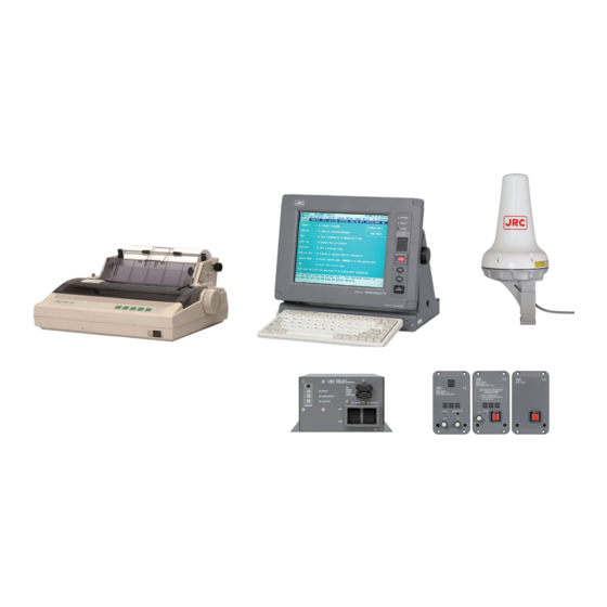
- Page 1 JUE - 87 INMARSAT - C INMARSAT MOBILE EARTH STATION MOBILE EARTH STATION ( EGC Receiver EGC Receiver ) INSTRUCTION INSTRUCTION MANUAL MANUAL...
- Page 3 ABOUT YOUR SAFETY CAUTIONS AGAINST HIGH VOLTAGE Radio and radar devices are operated by high voltages of anywhere from a few hundred volts up to many hundreds of thousands of volts. Although there is no danger with normal use, it is very dangerous if contact is made with the internal parts of these devices.
- Page 4 FIRST AID ☆Note points for first aid Unless there is impending danger leave the victim where he or she is, then begin artificial respiration. Once you begin artificial respiration, you must continue without losing rhythm. (1) Make contacts with the victim cautiously, there is a risk that you may get electrocuted. (2) Switch off the machinery and then move the victim away slowly if you must.
- Page 5 ☆ If the victim has a pulse but is not breathing (“Mouth to mouth” resuscitation) (1) Place the victim’s head facing backward (place something under the neck like a pillow). (2) Point the chin upward to widen the trachea. (3) Pinch the victim’s nose, take a deep breath, then put your mouth over the victim’s mouth and exhale completely, making sure that your mouth completely covers the victim’s mouth.
- Page 6 ☆ If the victim has no pulse and is not breathing (Heart massage in combination with artificial respiration.) If the victim has no pulse, his or her pupils are dilated, and if you cannot detect a heartbeat, the heart may have stopped, beginning artificial respiration is critical.
-
Page 7: Preface
PREFACE Thank you for purchase of the JRC Inmarsat-C, Mobile Earth Station, JUE-87. Please read this manual carefully and carry out proper operation. Please keep this manual importantly to refer to when it is necessary. Please use it when questions and troubles are caused in operation, by any chance. -
Page 8: Attentions Before Installation
ATTENTIONS BEFORE INSTALLATION JRC cannot accept responsibility for any loss due to incorrect operation, malfunction, and other causes except product guarantee condition and liability by law. There is possibility that some functions of the terminal may not operate correctly depend on the hardware and software version of equipment connected to the terminal. -
Page 9: Before Installation
BEFORE INSTALLATION About safety symbols This manual and the terminal are indicated the following safety symbols for your correct operation to prevent your and somebody’s injury or damage to the product and assets. The symbols and descriptions are as follows. You should understand well them before reading this manual and operating the terminal. -
Page 10: About Warning Labels
ABOUT WARNING LABELS Below mentioned warning labels are put on JUE-87. Do not take off, destroy, or modify these labels. Labels put on EME Labels put on IME <Type1> viii... - Page 11 <Type2>...
- Page 12 Immediately after printing, the printing head is still very hot, don’t touch it until it is cool down. WARNING Do not bring JUE-87 (EME) close to the fire, or put it in the fire. It causes the explosion, generation of heat. Do not approach the JUE-87 (EME) while transmitting, It transmits microwave and strong microwave might be cause injury.
- Page 13 Do not paint radome. Painting of radome may cause decrease of the communication quality. <IME> Do not use the IME to other purpose. It may cause a problem that unable to be transmitted in the emergency. NOTE This model does not transmit, however, warning labels are the same as JUE-87 original model.
-
Page 14: Acronyms And Abbreviations
ACRONYMS AND ABBREVIATIONS AC ......................Alternating Current ACK......................Acknowledgement AFC ..................Automatic Frequency Control AGC....................Automatic Gain Control ALM ..........................Alarm AMVER ..........Automated Mutual-assistance Vessel Rescue system A vessel position-reporting system operated by the United States Coast Guard for any merchant vessel of 1000grt or more on a voyage lasting longer than 24 hours, to and from anywhere on the world. - Page 15 BS ..........................Backspace Bulletin Board (in a TDM channel): A data packet transmitted in each frame of a TDM channel, which contains information about the status of the Inmarsat B/M, mini-M and C network configurations, and the current frame number, used by the MES as a timing reference. BUZ ..........................
- Page 16 CUG......................Closed User Group Private network used by the registered user only. Unregistered user cannot be accessed from public network. Data reporting: A short data packet transmitted in burst mode on the MES signaling channel as a result of a polling telecommand or at the initiative of the MES (operator). Data services: This is how a terminal may send and receive electronic messages such as e-mail.
- Page 17 EGC ...................... Enhanced Group Call The system for broadcasting messages via Inmarsat C mobile satellite communications system that supports two services: SafetyNET and FleetNET. EIA ..................Electronic Industries Association EIRP ..............Equivalent Isotropically Radiated Power Effective Isotropically Radiated Power, a measure of transmitted power. E-mail ......................
- Page 18 IA5 ..................International Alphabet number 5 A standard alpha- numeric character set, also known as ASCII, based on 7-bit codes. Supports both upper and lower case characters. ID ..........................Identity IF ...................... Intermediate Frequency IFU.................... Intermediate Frequency Unit IHO ..............International Hydrographic Organization IME ..................
- Page 19 LES TDM channel: A TDM channel used by an LES to transmit system information and data addressed to an MES. LMSS ..................Land Mobile Satellite Service Log in: The action performed on an Inmarsat C MES to inform the NCS in an ocean region that the MES is available for communications.
- Page 20 NAVAREA ....................Navigational Area A geographical sea area established for the purpose of coordinating the broadcast of navigational warnings. NAVTEX ............... MF Navigational Broadcast Service The system for The broadcast and automatic reception of Maritime Safety information by means of narrow-band direct-printing telegraphy. NCS ..................
- Page 21 PSTN ................Public Switched Telephone Network PSU ......................Power Supply Unit PVT ..................Performance Verification Test RAM ....................Random Access Memory RCC ..................Rescue Coordination Center RDB ....................Remote Distress Button REC ........................Receiving level ROM ......................Read Only Memory RX .........................
- Page 22 A format based on 7-bit codes used for sending the alphanumeric characters of the ASCII character set. 8-bit data: A format based on 8-bit codes used for encoding information such as text, national character sets and numerical information. NOTE This “ACRONYMS AND ABBREVIATIONS” is the same as JUE-87 original model.
-
Page 23: Table Of Contents
ACRONYMS AND ABBREVIATIONS ....................xii CHAPTER 1. GENERAL ........................1-1 CHAPTER 2. COMPOSITION ......................2-1 2.1 JUE-87 Installation Wiring Diagram, Components and Supplied Parts List ........ 2-1 2.1.1 Installation Wiring Diagram ...................... 2-1 2.1.2 Components List........................2-4 2.1.3 Supplied Parts by JRC ....................... 2-5 2.1.4 Parts for Installation (Prepared by Shipyard) ................ - Page 24 4.3.5 Model & Country mode Compatibility Window ..............4-18 4.4 Help Function ..........................4-19 CHAPTER 5. Specification ........................5-1 5.1 JUE-87 ............................5-1 5.1.1 EME (NAF-253GM) and IME (NTF-318) ................5-1 5.1.2 Printer (NKG-900/NKG-800) ....................5-2 5.1.3 EXT PSU (NBD-904) ........................ 5-3 APPENDIX 1.
-
Page 25: Chapter 1. General
CHAPTER 1. GENERAL This manual covers the installation, operation, and maintenance of the MES (Mobile Earth Station) JUE-87 for Inmarsat-C satellite communications. -
Page 27: Chapter 2. Composition
50/60Hz, 1φ, 160W INM-C-2 GN D Remote SEL+ [Dsub9] SEL- RDY+ Maintenance RDY- [Dsub9] DRQ+ DRQ- DRA+ [RJ-45] DRA- DAL+ DAL- 7ZCSC0325 JB Cable 5m *: SHIPYARD SUPPLY (JRC SUPPLY) Fig 2.1.1a Wiring Diagram Inmarsat-C JUE-87 Mobile Earth Station (Stand alone, JB1) - Page 28 (inner) 50/60Hz, 1φ, 160W GN D Remote SEL+ [Dsub9] SEL- RDY+ Maintenance RDY- [Dsub9] DRQ+ DRQ- DRA+ [RJ-45] DRA- DAL+ To JB2/JB2 PCB (2/2) DAL- *: SHIPYARD SUPPLY Fig 2.1.1b Wiring Diagram Inmarsat-C JUE-87 Mobile Earth Station (GM console, JB1)
- Page 29 JB2 NQE-3223 TB1(P1-25) TB2(P26-50) GN D EXT B UZ GN D 250V MPYC-4 NCE-5547 Max.100m BUZ2 EXT B UZ GN D 250V MPYC-4 NCE-5547 Max.100m BUZ3 GN D *: SHIPYARD SUPPLY Fig 2.1.1c Wiring Diagram Inmarsat-C JUE-87 Mobile Earth Station (JB2)
-
Page 30: Components List
NTF-318 Equipment) Keyboard NDF-369 Printer NKG-900/NKG-800 EXT PSU NBD-904 (Externally Power Supply Unit) Coaxial cable (Between IME coaxial cable and CFQ-5922A EME) JB1 Board CQD-2245A Spare parts 7ZXSC8702/7ZXSC8701 JUE-87 Instruction Manual 7ZPSC0444 JUE-87 Installation Manual 7ZPSC0446 JUE-87 Operation Guide 7ZPSC0448... -
Page 31: Supplied Parts By Jrc
2.1.3 Supplied Parts by JRC Table 2.1.3a Supplied parts by JRC for EME Installation Name Type Q’ty Remarks Application Single unit Fixing Band MPBP31867 by two Painting Protection Material MPXP33556 “SUMI” Tape (Self Bandaging Tape) BRXP05369 Packing List MTZ304557 Table 2.1.3b Supplied parts by JRC for IME Installation... -
Page 32: Parts For Installation (Prepared By Shipyard)
2.1.4 Parts for Installation (Prepared by Shipyard) Table 2.1.4 Required cables Part Description Q’ty Remarks Application PVC tape Vinyl tape L = 15m For protecting cable W = 30mm, Copper plate JIS H 3100 For grounding EME t = 0.2mm Pole For mounting EME 2.1.5 Required Tools... -
Page 33: Eme (Externally Mounted Equipment: Naf-253Gm)
2.2 JUE-87 2.2.1 EME (Externally Mounted Equipment: NAF-253GM) EME is connected to IME with a coaxial cable. The cable can be extended to maximum 100 m. Fig 2.2.1 EME... -
Page 34: Ime (Internally Mounted Equipment: Ntf-318)
2.2.2 IME (Internally Mounted Equipment: NTF-318) IME is consists of Interface Unit, Power Supply Unit, Process Circuit, Color LCD Unit, I/F Circuit and USB I/F Circuit. POWER LED Display READY LED COMM LED Distress BUTTON Screen Angle Adjust Knob Dimmer Power SWITCH USB PORT Keyboard... - Page 35 Fig 2.2.2b Back View of IME Table 2.2.2c Connectors and the Cable (Refer to Fig 2.2.2b) Name Connected from/to LAN Port PC or HUB for RMS KEYBOARD Port KEYBOARD SERIAL Port (Not USED) DTE Port JB2 Port PRINTER Port PRINTER JB1 Port EME Port PWR Port...
-
Page 36: Printer (Nkg-900/Nkg-800)
When status is off line: received message is not printed. Use a roll-paper (JRC code :5ZPAL00002/5ZPCM00020 for one-sheet copy and 5ZPCK00001for two-sheet copy) and ink ribbon (7ZZJD0105) While a power supply is on, it isn't possible to turn paper feed knob manually. - Page 37 When status is off line: received message is not printed. Use a roll-paper (JRC code :5ZPAL00002/5ZPCM00020 for one-sheet copy and 5ZPCK00001for two-sheet copy) and ink ribbon (5ZZCM00003) Do not use except above mentioned products, for keep normal operation.
-
Page 38: Ext Psu (External Power Supply Unit: Nbd-904)
2.2.4 EXT PSU (External Power supply Unit: NBD-904) The EXT PSU (NBD-904) supplies DC+24V for IME-EME and Printer from Ship’s power source (from 100 to 240V AC) and/or +24V DC. When both AC and DC power source are connected to the EXT PSU and the power interruption of AC power source is occurred: EXT PSU switches over from AC power source to the DC power source automatically (Power failure detecting function). -
Page 39: Coaxial Cable (Cfq-5922A)
2.2.6 Coaxial Cable (CFQ-5922A) Connecting EME and Antenna Cable. Fig 2.2.6 Coaxial Cable 2-13... -
Page 40: Dimensional Drawing
2.3 Dimensional Drawing 2.4.1 EME (NAF-253GM) Unit: mm Mass: Approx. 2.4 kg Color: N9 Fig 2.4.1 EME 2-14... -
Page 41: Ime (Ntf-318)
2.4.2 IME (NTF-318) Fig 2.4.2 IME 2-15... -
Page 42: Dte Keyboard (Ndf-369)
2.4.3 DTE Keyboard (NDF-369) Unit: mm Mass: Approx. 0.4kg Fig 2.4.3 DTE Keyboard 2-16... -
Page 43: Printer (Nkg-900/Nkg-800)
2.4.4 Printer (NKG-900/NKG-800) Fixing Unit: mm Mass: Approx.4.8kg Attach the hook and loop fastener to the bottom of the printer and the desk, and then fix them. Fig 2.4.4a Printer (NKG-900) 2-17... - Page 44 Fixing Unit: mm Mass: Approx.3.7kg Attach the hook and loop fastener to the bottom of the printer and the desk, and then fix them. Fig 2.4.4b Printer (NKG-800) 2-18...
-
Page 45: Ext Psu (Nbd-904)
2.4.5 EXT PSU (NBD-904) Serial Number Seal Dimmer Volume x 3 Mount Hole Fuse x 2 4-φ6x8 Refer to Table 5.1.3 Principal Specification of EXT PSU for detailed specifications. Unit: mm Mass: Approx. 2.6kg Fig 2.4.5 EXT PSU 2-19... -
Page 46: Jb1 (Nqe-3222)
2.4.6 JB1 (NQE-3222) Fig 2.4.6 JB1 2-20... -
Page 47: Coaxial Cable (Cfq-5922A)
2.4.7 Coaxial Cable (CFQ-5922A) Connecting EME and Antenna Cable. Max.22mm Max.8mm Minimum bending radius: 46mm Type Length Standard: CFQ-5922A3 30m(±10cm) Option: CFQ-5922A4 40m(±10cm) Option: CFQ-5922A5 50m(±10cm) Fig 2.4.7 Coaxial Cable 2-21... -
Page 49: Chapter 3. Operation
CHAPTER 3. OPERATION 3.1 Power ON - Initial setting - Power OFF NOTE Before turning on all power switches of JUE-87, confirm that all the signal cables and power cables are connected correctly. 3.1.1 Power ON When the power switch of IME is turned on, JUE-87 synchronizes with NCS TDM career(*). -
Page 50: Main Menu Display (Explanation Of Screens And Commands)
<Explanation of commands> JUE-87 has two kinds of way to operate the DTE, one is selecting command by cursor, and the other one is pressing the buttons directory. Direct commands make quicker and easy operation when you get used to the operation of DTE. - Page 51 (Initial setting) Transmit read-Out Edit call-Log Distress Ncs/les-info receive-Mode (EGC reception setting) Transmit read-Out Edit call-Log Distress Ncs/les-info receive-Mode (Read out received message setting) Transmit read-Out Edit call-Log Distress Ncs/les-info receive-Mode Fig 3.1.2b Selecting command in main menu area by cursor (2) Direct commands This model has two types of commands;...
-
Page 52: Initial Setting
3.1.3 Initial Setting After turn on the JUE-87 MES, set the following parameters; (1) Selecting Preferred Ocean Region (2) Setting Date & Time (1) Selecting Preferred Ocean Region (Ncs/Les info) When your ship navigates in more than one ocean region, confirm “All ocean region” is selected in “Preferred Ocean Region”... -
Page 53: Power Off
When the Date & time (displayed in the bottom line on the right side of the first screen) is wrong, correct the Date & time as follows. When the JUE-87 is synchronized with the NCS common channel, the time is reset at 00:00 (UTC) everyday by Inmarsat frame channel. -
Page 54: Egc Message Reception
3.2 EGC Message Reception 3.2.1 EGC Messages Two types of EGC message are offered and broadcasted to the all ships on the selected ocean region, and ships on specified area: 1) Safety NET This is the service, sending the information approved by IMO of each country (including RCC) to meet the GMDSS, for the ship’s safety voyage. -
Page 55: Settings For Egc Reception
The JUE-87 can restrict to EGC message reception with Navarea/Metarea, Fixed area, reception type, Satellite Coastal areas and Coastal Warning type. Choose “egC” on main menu to setup this function. Also JUE-87 has the function that printing EGC message automatically when received it. See “3.2.2.6”, when you want to set up this function. -
Page 56: Setting Of Navarea/Metarea
3.2.2.1 Setting of Navarea/Metarea Only receives the messages to Navarea/Metarea, which have been set up. NOTE Basically, information of Navarea/Metarea in the ocean region being logged in now is sent. Step Operation IME Response Remarks ・Move the cursor to “egC” and ・The “EGC”... - Page 57 Fig 3.2.2.1a Navarea/Metarea ocean region chart Navarea/Metarea Area 1 : Enable Area 12 : Enable Area 2 : Enable Area 13 : Enable Area 3 : Enable Area 14 : Enable Area 3 : Enable Area 15 : Enable Area 4 : Enable Area 16 : Enable Area 5 : Enable Area 17 : Enable...
-
Page 58: Setting Of Fixed Area
3.2.2.2 Setting of Fixed Area Step Operation IME Response Remarks ・Move the cursor to “egC” ・The “EGC” window is displayed. and press Enter key. ・When you want to change ・The cursor is moved to the fixed area, move the the “Fixed area” area. cursor to the “Fixed area”... -
Page 59: Setting Of Reception Type
3.2.2.3 Setting of Reception Type You can restrict below mentioned services at this menu. ・ Chart correction service (“charT correction service”) ・ Chart correction service for fixed area (“Chart correction service for fixed areas”) ・ Download group ID (“Download group identity”) ・... -
Page 60: Setting Of Satellite Coastal Areas
3.2.2.4 Setting of Satellite Coastal Areas The JUE-87 can restrict the Satellite Coastal Area message of the A through Z areas. Choose the area you want to receive or restrict from these areas. Satellite coastal areas A: Enable N: Enable... -
Page 61: Setting Of Coastal Warning Type
3.2.2.5 Setting of Coastal Warning Type The JUE-87 can restrict the Coastal Warnings mentioned below. ・ other Electronic navaid messages ・ Pilot and VTS service messages ・ Ice reports ・ GNSS messages ・ Loran messages ・ no message on Hand ・... - Page 62 Step Operation IME Response Remarks ・Move the cursor to “egC” ・The “EGC” window is displayed. and press Enter key. ・Move the cursor to “coastal ・The “Coastal warning Warning type” and press type” window is displayed. Enter key. ・When you want to restrict the ・The cursor is moved to Coastal warning, move the “Enable”...
-
Page 63: Setting For Message Print Out Function
3.2.2.6 Setting for Message Print Out Function When the JUE-87 is received the EGC or Inmarsat-C message, the received message is printed out automatically that is the message print out function. When this function is turned off or on according to the following procedure. -
Page 64: Handling Received Messages (Read-Out, Printing, Saving, And Deleting)
REFERENCE JUE-87 has function that EGC message is read out from JRC MFD via LAN. Please refer to the MFD’s documentation about the MFD corresponding to this function and the operation method. - Page 65 (2) To delete the message Step Operation IME Response Remarks “Inm-C”:“Inm-C message list” ・Move the cursor to ・“Read-out” window is “Egc” :“Egc message list” “read Out” and press displayed. It shows three “All” :“Reception message list” types of message list. Enter key.
- Page 66 EGC message list No. Date Time Priority Size Service 1. 14-04-01 05:03 *Distress 200 *General call 2. 14-04-01 04:59 *Urgent 200 *General call 3. 14-04-01 04:52 *Routine 200 *General call 4. 14-04-01 04:52 Safety 200 *General call ↑↓ contd.(total : Residual : Kbytes) F1: Delete...
-
Page 67: Chapter 4. Maintenance
CHAPTER 4. MAINTENANCE 4.1 Maintenance Keep the equipment in a good state according to the following maintenance. 4.1.1 Daily Maintenance 4.1.1.1 Mechanical Maintenance 1) Cleaning Keep the equipment as clean as possible. In particular, wipe the ventilation opening with a dry cloth. 2) Tightening of screws Check screws in all parts of the equipment and tighten any loosen one. -
Page 68: Troubleshooting
Check all items in the following section to secure normal communication at all times. When any unusual phenomenon occurs in the equipment, send appropriate information to JRC service network to get advice or to request for repair with the results of these items. - Page 69 EME-IME Is the EME-IME Cable cable normal? Exchange Is the DC resistance of EME pig tail cable approx.7kΩ? Exchange Contact JRC Is terminal Is there any Is the Ocean synchronized after 2 to 10 Region setting blocking? minutes passed? incorrect?
-
Page 70: Alarm Check
4.2.2 Alarm Check The JUE-87 provides the following function, which is useful for maintenance and for prompt detection of faults on the equipment. Various operation states and alarm states are displayed on the first line of the screen of IME and alarm history is displayed as the following procedure. - Page 71 Table 4.2.3 Contents of Alarm history Display format Content (In case of Fig.4.2.3) IMN:4XXXXXXXX MES Number ① (IMN:410032123) SER:XXXXXX Serial Number ② (SER:068577) EME Board Version (XX) HW:XX/Y ③ (HW:01/4) IME Board Version (Y) ACSE Main Version (XX.XX) ACSE:XX.XX/Y.Y ④ (ACSE:01.00/2.0) ACSE SAFE Mode Version (Y.Y) MDM:XX.XX...
- Page 72 Receiver AGC setting value (UU) shows the gain control value to adjust level of current receiving signal. Normal value : from 80(hex) to E0 (Hex) Lower value shows that receiving signal is stronger and receiver circuit performance is better. Receiving C/N0 (VVVV) shows 10 times C/No dBHz. This value depends on both received signal from satellite and receiver circuit performances.
- Page 73 No alarm (If there are any alarm, 0x000000 Add the following each status value) EME ROM data alarm + 0x800000 EME RAM data alarm <Note> + 0x400000 If user stops power supply without “Log-out”, this bit becomes “high”. + 0x200000 EEPROM data alarm EEPROM FATAL alarm + 0x100000...
- Page 74 “MD2” values are fixed for each terminal. They show transmitter hardware set value in factory. If MD2 values is all zeros or all “F”, JUE-87 can not transmit normally. In that case, contact the JRC service agent and let us know about Alarm history of your JUE-87.
-
Page 75: Countermeasure
4.2.4 Countermeasure If the equipment does not operate in normal even after the following procedure is performed, consult JRC service agent. Take care not to touch any parts on PC board. Abnormal operation of IME/DTE In case of the heavy fluctuation of the voltage or frequency of the power source, or thunderbolt and etc., IME may not operate normally. -
Page 76: After Service
Disposal of JUE-87 When disposing JUE-87 process it in accordance with the rules of the pertinent local government. For details, contact to the purchasing dealer from which you purchased, our service office or a pertinent local government. -
Page 77: Pop-Up Window
4.3 Pop-up Window JUE-87 has the following pop-up windows. The information window is displayed when the JUE-87 have some trouble or some warning. (1) WARNING Window (2) CAUTION Window (3) ERROR Window (4) MES Information Window (5) Model & Country mode Compatibility Window When the window is displayed, follow the instruction in the window. -
Page 78: Warning Window
Therefore, print out the call logging data. Transmitter over loaded. It Contact the purchasing dealer, JRC may be permanent damaged. agent or one of the JRC branches. Window overflow Windows of the DTE are opened Press F10 key to close the window maximum numbers. -
Page 79: Caution Window
4.3.2 CAUTION Window The examples of the message of CAUTION window are listed in Table 4.3.2. CAUTION No position data. Press F10 key to input data. Fig 4.3.2 CAUTION window Table 4.3.2 Message list of CAUTION window Caution Message Cause Countermeasure EGC message storage in DCE is Delete unnecessary messages. -
Page 80: Error Window
4.3.3 ERROR Window The examples of message of ERROR window are listed in Table 4.3.3. ERROR USB drive is not ready. Insert USB drive and press Enter key. F10: Previous Fig 4.3.3 ERROR Window Table 4.3.3 ERROR Message ERROR Message Cause Countermeasure Cannot create the new file. - Page 81 ERROR Message Cause Countermeasure The DTE main drive is Can not access the DTE Press ENTER key to re-read the unreadable. Flash ROM Flash ROM. Press ENTER key to retry. If the same window is displayed, the Flash ROM might be troubled. The file is missing.
-
Page 82: Mes Information Window
4.3.4 MES INFORMATION Window The examples of the messages of Information window are listed in Table 4.3.4. Now reading data. Please wait. Fig 4.3.4 MES INFORMATION Window Table 4.3.4 MES INFORMATION Message INFORMATION message Countermeasure 2nd LES ID Invalid Because of Demand Assigned LES Are you sure you want to rename the file? Can not create new file. - Page 83 INFORMATION message Countermeasure Now printing. Please wait. When the display doesn't disappear, the breakdown of the printer is thought. In this case, please OFF/ON it the power supply of the printer. Now reading data. Please wait Do not remove a diskette during data reading.
-
Page 84: Model & Country Mode Compatibility Window
① In case of EME and IME (DTE unit) are incompatible with country mode. Example: JUE-87 EME (Russian model) is connected to JUE-87 IME (DTE unit: Standard model). The following message is displayed. To close this window, press F10 (“Previous”) key. -
Page 85: Help Function
②In the case of EME and IME (DTE unit) are incompatible with model. Example: JUE-85EME ( NAF-253GM) is connected to JUE-87 IME (DTE unit: Standard model). The following message is displayed. To close this window, press F10 (“Previous”) key. Example: JUE-95SA EME (NAF-253SA) is connected to JUE-87 IME (DTE unit: Standard model). - Page 86 4-20...
-
Page 87: Chapter 5. Specification
CHAPTER 5. Specification 5.1 JUE-87 5.1.1 EME (NAF-253GM) and IME (NTF-318) Table 5.1.1 Principal Specification of JUE-87 Item Specification Class of Inmarsat-C MES Class 2 Transmission: 1626.5 to 1646.5MHz Frequency Range Reception :1537.0 to 1544.2MHz Channel Spacing: 5KHz -23.0 dB/K minimum Within 14 2 dBW (at 5 degrees elevation angle) -
Page 88: Printer (Nkg-900/Nkg-800)
Character Per Line Roll Paper Size Recording paper (1PLY) 214mmW 98mmφ 5ZPAL00002 Recording paper (1PLY) 214mmW 100mmφ 5ZPCM00020 Ink Ribbon Type: 7Q1VP80S JRC Code: 7ZZJD0105 Color: Black Power Supply DC +24V (+19.2 to +31.2V) Power Consumption Approx. 35W (max) 390.2 mm (W) 355.2 mm (D) 175.8 mm (H) -
Page 89: Ext Psu (Nbd-904)
5.1.3 EXT PSU (NBD-904) Table 5.1.3 Principal Specification of EXT PSU Item Specification Line voltage AC: from +100V to +220V /DC: +24V Line voltage range AC:+89V to +266V/ DC:+19.2 to +31.2V Line frequency range 47 Hz to 64Hz Function ・ DC power automatic backup at AC power failure. ・... -
Page 91: Appendix 1. Inmarsat System Coverage Areas
APPENDIX 1. INMARSAT SYSTEM COVERAGE AREAS Over lapped areas Pacific Pacific Atlantic Atlantic Indian Ocean Ocean Ocean Ocean Ocean Region Region Region Region Region West East Fig A1.1 All Ocean Region Fig A1.2 Atlantic Ocean Region West Fig A1.3 Atlantic Ocean Region East Fig A1.4 Pacific Ocean Region Fig A1.5 Indian Ocean Region A1-1... - Page 92 A1-2...
-
Page 93: Appendix 2. Nkg-900 Printer Installation Guide
APPENDIX 2. NKG-900 PRINTER INSTALLATION GUIDE Concerning details, please refer to the installation manual for each equipment. Contents Page 2.1 Cautions for use ........................... A2-2 2.2 Outline and name of component ....................A2-3 2.2.1 Supplied accessories ......................A2-3 2.2.2 Components names ......................A2-3 2.3. -
Page 94: Cautions For Use
A2.1 Cautions for Use Don’t touch immediately after printing as the printing head is still very hot. To set the ribbon, pay attention not to twist the ribbon. To turn on the power again after once turned OFF, wait at least 2 seconds. If this is not respected, ... -
Page 95: Supplied Accessories
A2.2. Outline and Names of Components A2.2.1 Supplied Accessories The following items are included as part your purchase 1) Printer 6) Fix tape 2 pairs 2) Ribbon Cartridge (Black) 7) Stand holding screw 2 pcs. 3) Printer Cover 4) Roll Paper Stand Unit 5) Fuse A2.2.2 Components Names Friction lever... -
Page 96: Fix Tape Attachment
A2.3. Installation A2.3.1 Fix Tape Attachment Attach fix tape to a base to fix NKG-900. Peel off a blue protection seat of fix tape, then attach fix tape according to the frame line. After attaching fix tape to the printer side, peel off a yellow protection seat and install printer in mounting point. -
Page 97: Change Of Ink Ribbon Cartridge
A2.3.2 Change of Ink Ribbon Cartridge 1) Verify that the power switch remains turned OFF. 2) Open the printer cover. 3) Lift up the ink ribbon cartridge by holding the projection on the cartridge. 4) Using the knob on the new cartridge make the ribbontaut. Ink ribbon cartridge 5) Manually move the print head to the left... -
Page 98: Roll Paper Loading
A2.3.3 Roll Paper Loading 1) Verify that the pover switch remains turned OFF. 2) Open the printer cover. 3) Remove the roll paper cover. At this step, pull the friction lever towards the front. 4) Pass the roll bar through the roll paper, and install the roll paper onto the roll paper stand in the right direction. - Page 99 8) Restore the roll paper cover and the roll support cover, then close the printer cover. A2.3.4 Connection of paper end near sensor Connect a sensor cable of a roll paper stand to the sensor cable connector on the printer rear left side. A2.3.5 Connection with Terminal Prior to connect, verify that for both the terminal and printer their power switch is turned OFF.
- Page 100 A2.4. Self-printing Function This printer is provided with self-printing function in order to check printing quality or printer’s condition prior to use. However, with this self-printing function, the printer port is not checked. Prior to perform self-printing, verify at first the paper is set. NOTE If printing is made directly on the platen without ribbon and paper, the platen or printing head may be damaged.
-
Page 101: Appendix 3. Nkg-800 Printer Installation Guide
APPENDIX 3. NKG-800 PRINTER INSTALLATION GUIDE Concerning details, please refer to the installation manual for each equipment. Contents Page 3.1 Cautions for use ........................... A3-2 3.2 Outline and name of component ....................A3-3 3.2.1 Supplied accessories ......................A3-3 3.2.2 Components names ......................A3-3 3.3. - Page 102 A3.1 Cautions for Use Don’t touch immediately after printing as the printing head is still very hot. To set the ribbon, pay attention not to twist the ribbon. To turn on the power again after once turned OFF, wait at least 2 seconds. If this is not respected, ...
- Page 103 A3.2. Outline and Names of Components A3.2.1 Supplied Accessories The following items are included as part your purchase 1) Printer 6) Fix tape 2 pairs 2) Ribbon Cartridge (Black) 7) Cap 2 pcs. 3) Printer Cover 8) Stand holding screw 2 pcs.
- Page 104 A3.3. Installation A3.3.1 Fix Tape Attachment A3-4...
- Page 105 A3.3.2 Change of Ribbon Cassette-cartridge Mounting method 1) Verify that the power switch remains turned OFF. 2) Turn the cassette knob in arrow mark direction to give tension to the ribbon. 3) In case of paper stand has been mounted, loosen stand-holding screw, and slide the paper stand backward.
- Page 106 Dismounting method 1) To change the ribbon, at first verify that the power to printer is turned OFF. 2) In case of paper stand has been mounted, loosen stand-holding screws, and slide the paper stand backward. 3) Remove the printer cover. 4) Seize the ribbon cassette knob, rise up vertically to remove.
- Page 107 A3.3.4 Roll Paper Loading Paper holder mounting Paper holder mounting 1) Insert the roll paper stand into guides on right and left Loading of roll paper 1) Cut off broken or folded end of roll paper. 2) Inset roll core to roll. 3) Pull toward you the sensor guide lever.
- Page 108 Roll paper setting 1) In case of paper stand has been mounted, loosen stand holding screws and slide the paper stand backward. 2) Remove the printer cover. 3) Push back the friction lever. 4) Pass the roll paper on paper guide bar, insert it in paper chute, pull it out from front of the platen.
-
Page 109: Connection Of Paper End Near Sensor
Mount of roll paper cover 1) Mount the roll paper cover as shown in Fig. 2) Push up the paper support lever. Connection of paper end near sensor Connect the sensor cable on the back as shown in Fig. Upon accomplishment of the above, the state becomes as shown in Fig. below. Then mount the printer cover. -
Page 110: Connection With Terminal
A3.3.5 Connection with Terminal Prior to connect, verify that for both the terminal and printer their power switch is turned OFF. 1) Connect the printer cable to the parallel interface connector located on back of the printer, then, fix with locking lever. 2) Connect the other end of cable to the terminal. -
Page 111: Self-Printing Function
A3.4. Self-printing Function This printer is provided with self-printing function in order to check printing quality or printer’s condition prior to use. However, with this self-printing function, the printer port is not checked. Prior to perform self-printing, verify at first the paper is set. NOTE If printing is made directly on the platen without ribbon and paper, the platen or printing head may be damaged. -
Page 113: Appendix 4. Jrc Service Network
APPENDIX 4. JRC Service Network Please contact the dealer from which you purchased the device or our marketing offices that is nearest to you for any question as to the after-sales service. JRC web site JRC Tokyo http://www.jrc.co.jp JRC Seattle http://www.jrcamerica.com... - Page 118 Not use the asbestos For further information,contact: URL Head office : http://www.jrc.co.jp/eng/ Marine Service Department : msc@jrc.co.jp e - mail One - call : +81-50-3786-9201 ISO 9001, ISO 14001 Certified CODE No.7ZPSC0563 OCT. 2016 Edition 3...
Need help?
Do you have a question about the JUE-87 and is the answer not in the manual?
Questions and answers
WHEN I MAKE A TEST FROM OTHER VESSELS PAPER OUT ALAM INDICATING BUT WHEN I TEST WITH SELF TEST ITS PRINTING
The JRC JUE-87 alarm may indicate a paper out when testing with other vessels but still print during a self-test because the printer can operate briefly using remaining paper during the self-test, or the paper sensor may not detect low paper accurately in all test modes. Additionally, paper detection might behave differently under external test conditions compared to internal self-tests.
This answer is automatically generated