Table of Contents
Advertisement
To buy, sell, rent or trade-in this product please click on the link below:
http://www.avionteq.com/Druck-GE-Sensing-ADTS-405-ADTS-405F-Air-Data-Test-Set-Systems.aspx
GE
Sensing
Druck ADTS 405
Air Data Test Systems
User Manual K114
www.avionteq.com
101 3. 25 mba r
Ps
101 3. 25<
Aim
319 9. 91 mba r
Pt
320 0. 00
Aim
Advertisement
Table of Contents

Related Manuals for GE Druck ADTS 405


Summary of Contents for GE Druck ADTS 405
- Page 1 To buy, sell, rent or trade-in this product please click on the link below: http://www.avionteq.com/Druck-GE-Sensing-ADTS-405-ADTS-405F-Air-Data-Test-Set-Systems.aspx Sensing www.avionteq.com Druck ADTS 405 Air Data Test Systems 101 3. 25 mba r User Manual K114 101 3. 25< 319 9. 91 mba r...
- Page 2 © General Electric Company. All rights reserved.
- Page 3 Druck ADTS 405 Air Data Test Systems User Manual K114 101 3. 25 mb ar 101 3. 25< 319 9. 91 mb ar 320 0. 00 K114 Issue No. 9...
- Page 4 K114 Issue No. 9...
- Page 5 Druck ADTS 405 User Manual Introduction This technical manual provides operating instructions for the Air Data Test System compatible with the requirements of first line servicing. Scope This technical manual contains a brief description, operation and testing procedures for the user of this equipment.
-
Page 6: Associated Publications
Associated Publications This lists the Druck manuals and publications referenced in this manual. Maintenance Manual K244 Air Data Test System ADTS 405 Calibration Manual K199 Air Data Test System ADTS 405 IEEE 488 OPT 2 Manual K154 Air Data Test System ADTS 405 SCPI IEEE 488 Manual K157 Air Data Test System ADTS 405... -
Page 7: Table Of Contents
CONTENTS Table of Contents Preliminary pages Introduction ................................i Scope ................................i Associated Publications ................................ ii Symbols ................................ii Table of contents (this table) ............................. iii Abbreviations ................................viii Glossary ................................ix Returned Goods Procedure for Europe ......................... xi Returned Materials Procedure for USA .......................... xii Approved Service Agents .............................. - Page 8 Druck ADTS 405 User Manual Table of Contents (contd) Section page True Airspeed .............................. 3-21 Airspeed Switch Test ..........................3-22 Engine Pressure Ratio (EPR) ......................... 3-23 3.15 Testing Aircraft Systems or UUT ....................... 3-24 3.15.1 Go to Ground and Shut-Down .................... 3-24 3.16...
- Page 9 CONTENTS Table of Contents (contd) Section page SPEED Qc ............................6-2 MACH Pt ............................6-3 EPR ..............................6-4 ROC Ps RATE ..........................6-4 RATE TIMER ........................... 6-4 HOLD ............................... 6-5 RATE ..............................6-6 LEAK MEASURE/CONTROL ..................... 6-6 GROUND ............................6-7 PORT ..............................
- Page 10 Druck ADTS 405 User Manual Table of Contents (contd) Section page MINIMUM SET-UP ................................6-26 SETUP, [UNITS], [AERO] ......................6-26 SETUP, [UNITS], [PRESS] ......................6-26 SETUP, [LIMITS] ........................... 6-26 SETUP, ALT/Ps ..........................6-27 SETUP, PORT ..........................6-27 SETUP, HELP ..........................6-27 CONFIGURATION ............................
- Page 11 Table of Contents (contd) Section page CONFIG, PORT ..........................6-34 CONFIG, REMOTE ........................6-34 CONFIG, ETP,[AUTO RUN] ....................... 6-34 CONFIG, ETP,[ERASE PROGRAMS] ..................6-34 CONFIG, ETP,[RESULT] ......................6-34 CONFIG, (nudge keys) ....................6-34 CONFIG, 000 ..............................6-34 Specification ..............................6-35 Zone 2 Hazardous Area Definition ....................
-
Page 12: Abbreviations
Druck ADTS 405 User Manual viii Abbreviations The following abbreviations are used in this manual; the abbreviations are the same in the singular and plural. Ampere Absolute a.c. Alternating current Altitude ATEX Equipment for Use in Potentially Explosive Atmosheres Calibrated airspeed d.c. -
Page 13: Glossary
Glossary Glossary Terminology The terminology used in this manual is specific and individual interpretation must not be introduced. The terms are defined as follows: Adjust To bring to a more satisfactory state; to manipulate controls, levers, linkages, etc. to return equipment from an out-of-tolerance condition to an in-tolerance condition. - Page 14 Druck ADTS 405 User Manual Power-down: To perform operations necessary to safely switch off a system after use. Readjust: To adjust again; to move back to a specified condition; to bring back to an in-tolerance condition. Reconnect: To rejoin or refasten that which has been separated.
-
Page 15: Returned Goods Procedure For Europe
Returned Goods Procedure for Europe Should the unit become unserviceable and require repair it can be returned to the Druck Service Department. Please contact our Service Department, either by 'phone, fax or e-mail to obtain a Returned Goods Authorization (RGA) number, providing the following information: Product (i.e. -
Page 16: Returned Materials Procedure For Usa
Returned Material Procedure for USA Should the equipment become unserviceable it can be returned to the Druck Service Department. Please contact our Service Department, either by 'phone, fax or e-mail to obtain a Returned Material Authorization (RMA) number, providing the following information: Product (i.e. -
Page 17: Atex Certified Adts Hand Terminal
xiii ATEX Certified ADTS Hand Terminal CONDITIONS OF USE The ATEX certified ADTS hand terminal supplied with the ADTS 405 can be used in zone 2 hazardous areas in accordance with the ATEX certification document and schedule. ATEX Certificate of Conformity No. -
Page 18: Pressure Units And Conversion Factors
Pressure units and conversion factors f b l t f / f b l n i / ) i s c / f t f / l t f / n i / Table of pressure units and conversion factors Unit Conversion To convert FROM pressure VALUE 1 in pressure UNITS 1 TO pressure VALUE 2 in pressure UNITS 2, calculate as follows:... -
Page 19: Description
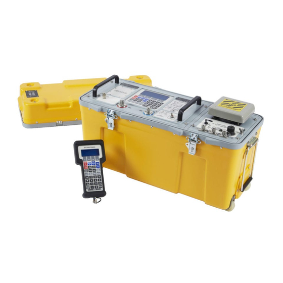
Description 1 - 1 DESCRIPTION Introduction There are two versions of the ADTS 405, a 19", 6U high (10½”) rack-mounted unit and a flight line unit. The ADTS 405 is a rack-mounted system and, with external pressure and vacuum supplies connected, provides measurement and control for leak checks, calibration accuracy checks and functional tests of air data instruments, components and systems. - Page 20 1 - 2 Druck ADTS 405 User Manual 10 13 . 25 mb ar 10 13 . 25 < 31 99 . 91 mb ar 32 00 . 00 1-1 ADTS 405 G IGURE ENERAL VIEW 1-2 ADTS 405F G...
-
Page 21: Operating Range And Performance
Description 1 - 3 Operating Range and Performance The ADTS 405 is supplied in one of two full-scale ranges (850 knots or 1000 knots) for measurement and control of the pitot pressure channel. Operating limits are set, pre-defined tabular limits known as STANDARD, CIVIL and MAX these can be selected through the SETUP menu (see Reference section 6). - Page 22 1 - 4 Druck ADTS 405 User Manual 1000 knot range operating limits / t f / t f / t f K114 Issue No. 9...
-
Page 23: Installation
Installation 2 - 1 INSTALLATION Packaging On receipt of the ADTS 405 check the contents of the packaging against the following lists: Packaging List - ADTS 405F Packaging List - ADTS 405 Flight line ADTS 405F Rack ADTS 405 Accessory bag Power supply cable iii) Power supply cable... - Page 24 2 - 2 Druck ADTS 405 User Manual Procedure The unit should be at zero/ambient pressure. Disconnect the hose assemblies and stow in the shoulder bag. Switch OFF and disconnect from the electrical power supply. Disconnect the power supply cable and the hand terminal cable. Disconnect the hand terminal cable from the hand terminal.
-
Page 25: Figure 2-1 Equipment And Parts
Installation 2 - 3 2.1 E IGURE QUIPMENT AND ARTS K114 Issue No. 9... - Page 26 2 - 4 Druck ADTS 405 User Manual , t i ATEX certified , l a , e l , e l , e l , e l c i t , ) s a l i ) e l...
-
Page 27: Electrical Connection
Installation 2 - 5 Electrical Connection WARNINGS: 1 VOLTAGES IN EXCESS OF 30 VOLTS (RMS) AC OR 50VOLTS DC, IN CERTAIN CIRCUMSTANCES, CAN BE LETHAL. CARE MUST BE TAKEN WHEN WORKING ON LIVE, EXPOSED CONDUCTORS. DO NOT DISCONNECT THE HAND TERMINAL WHEN ENERGIZED IN THE HAZARDOUS AREA. - Page 28 2 - 6 Druck ADTS 405 User Manual Flight line units Make sure that the power supply is off before connecting the power cable and hand terminal cable. Note: The flight line version power cable supplies both the electronics and pump racks.
-
Page 29: Pneumatic Pressure Connections
Installation 2 - 7 Pneumatic Pressure Connections ADTS 405 rack-mounted unit Static (Ps) ..........................AN-6 37° flare Pitot (Pt) ..........................AN-4 37° flare Pressure supply ........................AN-4 37° flare Vacuum supply ........................AN-6 37° flare Connect pressure and vacuum supplies to the rear panel PRESSURE and VACUUM connectors. -
Page 30: Positioning Of The Adts 405
2 - 8 Druck ADTS 405 User Manual Single channel operation For single pipe testing of airspeed indicators or similar, requiring only Pt (pitot), connect the UUT to Pt (pitot). The Ps (static) output must be left open to atmosphere (no blanking cap) to provide a reference pressure. -
Page 31: Positioning Of The Adts 405F
Installation 2 - 9 Positioning of the ADTS 405F WARNING: DO NOT DISCONNECT THE ATEX CERTIFIED HAND TERMINAL WHEN ENERGIZED IN THE HAZARDOUS AREA. THIS CAN CAUSE AN EXPLOSION. To operate safely, the ADTS 405F must be placed outside the user defined zone 2 hazardous area. - Page 32 2 - 10 Druck ADTS 405 User Manual K114 Issue No. 9...
- Page 33 Installation 2 - 11 K114 Issue No. 9...
- Page 34 2 - 12 Druck ADTS 405 User Manual K114 Issue No. 9...
-
Page 35: Operation
Druck ADTS 405 User Manual 3 - 1 OPERATION Preparation WARNING: OBSERVE SAFETY PRECAUTIONS STATED IN LOCAL ORDERS AND THE AIRCRAFT OR EQUIPMENT SERVICING PROCEDURES. Make sure the electrical and pneumatic connectors, electrical cables and pipes and positioning of the ADTS 405 comply with the instructions and requirements in Section 2 Installation. -
Page 36: Display Functions And Units Of Measure
3 - 2 Operation Display Functions and Units of Measure When operating in either pressure measuring or pressure controlling modes, the ADTS 405 can display the following information: Aeronautical Functions Display Abbreviation Displayed Units (if applicable) Altitude ft, m Calibrated and True Airspeed CAS, TAS kts, km/h, mph Mach... -
Page 37: Quick Reference
Druck ADTS 405 User Manual 3 - 3 Quick Reference The quick reference chart shows normal operation key functions. In the key/selection column the following applies: Key. [NEXT] Item in menu (soft key). (SINGLE DOUBLE) Sequence of parameters selected by NEXT key. -
Page 38: First Time Operators
3 - 4 Operation First Time Operators The following sequences of operation should be used by first time operators and by operators that use the equipment occasionally. For regular users, familiar with the equipment, go to section 3.5. Set the power supply switch to OPERATE and the power- up routine starts. - Page 39 Druck ADTS 405 User Manual 3 - 5 The system opens the zero valves and after approximately 7 seconds the valves close and the routine continues with the display shows: Measuring Ground Pressures PLEASE WAIT The system opens the output valves and controls pressures at the original measured values.
-
Page 40: Measure Mode
3 - 6 Operation Measure Mode To select the measured parameter press: STATIC PITOT SPEED MACH Units of Measured value measurement Measured 10000 parameter Leak Measure Leak Measure "leak-measure" when measure mode selected Change display Change units from aeronautical single, dual or triple to pressure: press:... - Page 41 Druck ADTS 405 User Manual 3 - 7 Control Mode K114 Issue No. 9...
- Page 42 3 - 8 Operation Leak Measure Mode Note: Compressing a gas generates heat. Gas heated or cooled in an enclosed volume causes a pressure change. It is important, especially for leak testing, to allow enough time for the heated gas to cool and the pressure to stabilize. When setting the rate timer consider three factors: The volume of the system to be tested (large volumes take longer to stabilize).
- Page 43 Druck ADTS 405 User Manual 3 - 9 Go to Ground K114 Issue No. 9...
-
Page 44: 3.5 Operation And Example Procedures
3 - 10 Operation 3.5 Operation and Example Procedures 3.5.1 Checks Before Use Inspection and Cleaning Inspect the external of the ADTS 405, and its associated equipment, for damage, dirt, and the ingress of moisture. If necessary, use foam cleaner and a lint-free cloth to clean the external surfaces. -
Page 45: Control Or Measure Parameter
Druck ADTS 405 User Manual 3 - 11 The ADTS 405 system may now be used but for full specification accuracy and stability, wait the "WARMUP" period of 15 minutes. The display shows “WARMUP” in the lower right hand corner, this message clears automatically after the time period. -
Page 46: Leak Testing The Adts 405
3 - 12 Operation Leak Testing the ADTS 405 It is important to check that the ADTS 405 and the connecting equipment does not leak. Before use a leak check should be carried out as follows: Connect the pitot and static hoses (to front panel of ADTS 405F). Temporarily seal the free ends of the hoses. - Page 47 Druck ADTS 405 User Manual 3 - 13 To apply an altitude of 5000 ft at a rate of climb of 6000 ft/min and an airspeed of 300 kts at a rate of 600 kts/min press the following keys: SPEED/Qc then RATE to select rate of change of speed.
- Page 48 3 - 14 Operation Leak Measure Note: Compressing a gas generates heat. Gas heated or cooled in an enclosed volume causes a pressure change. It is important, especially for leak testing, to allow enough time for the heated gas to cool and the pressure to stabilize. Press LEAK MEASURE/CONTROL to return to Leak Measure mode.
-
Page 49: Displays
Druck ADTS 405 User Manual 3 - 15 Displays (Fig 3.4, Fig 3.5 and Fig 3.6) The display normally shows pressures and rates or aeronautical equivalents. It can be set-up to show, at the same time, one parameter (single), two parameters (dual) or three parameters (triple). -
Page 50: Figure 3-5 Dual Display
3 - 16 Operation 3-5 D IGURE ISPLAY 3-6 T IGURE RIPLE ISPLAY K114 Issue No. 9... -
Page 51: Rate Timer Displays
Druck ADTS 405 User Manual 3 - 17 3.10 Rate Timer Displays (Fig 3.7 and Fig 3.8) When in Leak Measure mode and, after completing a rate timing, the system generates the rate timer displays. These displays do not depend on the display mode (single, dual, triple or option). -
Page 52: Pt Only Display
3 - 18 Operation 3.11 Pt Only Display (Fig 3.8) The Pt only display overrides the other display modes (single, dual and triple). The measured altitude and the CAS are produced from Ps in measure mode. 3-9 P IGURE ISPLAY 3.12 Changing the Display The display can show either one, two or three parameters as follows: Note: Display cannot be changed with SETUP switched off or in minimum mode. -
Page 53: 3.13 Changing The Units
Druck ADTS 405 User Manual 3 - 19 3.13 Changing the Units The units can be changed to units of pressure measurement or aeronautical units. In Full Set-up Mode any set of aeronautical or pressure units can be selected. To change the units: Press the SETUP key. - Page 54 3 - 20 Operation Using the SETUP function, previously stored sets of limits can be recalled for use. Each set of limits is stored under an aircraft name. Three pre-defined sets of limits “Standard“, “Civil“ and “Max“ limits are supplied with the ADTS 405. Note: The ADTS 405, when delivered, contains "Standard"...
-
Page 55: Aircraft System Protection
Druck ADTS 405 User Manual 3 - 21 Aircraft System Protection The ADTS 405 protects the aircraft system against user error and leaks in the aircraft system. Note: The pumps must be switched on. The system protection operates: Limit checking of user entered set-points. -
Page 56: Airspeed Switch Test
3 - 22 Operation Airspeed Switch test The following example shows how an airspeed switch an be functionally checked. Note: For low airspeed switches (i.e. 130 knots) the Pt Only facility could be used. Press LEAK MEASURE/CONTROL to enter control mode. Press SPEED/Qc. If necessary, press RATE and enter a change of airspeed low enough to observe switch operation. -
Page 57: Engine Pressure Ratio (Epr)
Druck ADTS 405 User Manual 3 - 23 Engine Pressure Ratio (EPR) The ADTS 405 may be used to check EPR sensors and indicators. Use Ps for INLET pressure and Pt for OUTLET pressure. To carry out an EPR check, the display must be showing pressure units e.g., mbar or inHg. -
Page 58: 3.15 Testing Aircraft Systems Or Uut
3 - 24 Operation 3.15 Testing Aircraft Systems or UUT WARNING: OBSERVE THE APPROPRIATE SAFETY INSTRUCTIONS AND PROCEDURES DETAILED IN THE AIRCRAFT MAINTENANCE MANUALS OR COMPONENT MAINTENANCE MANUALS. Connect the hoses and appropriate adaptors to the aircraft system or UUT. To make sure that the connections to the aircraft system or UUT are not leaking carry out a leak test detailed in the appropriate aircraft or component manual. -
Page 59: 3.16 Options
Druck ADTS 405 User Manual 3 - 25 3.16 Options WARNINGS: COMPLY WITH ALL LOCAL SAFETY ORDERS. OBSERVE ALL SAFETY PROCEDURES IN THE AIRCRAFT MAINTENANCE MANUALS. SCPI IEEE 488 Option The SCPI IEEE 488 interface provides remote control of the ADTS 405 from a suitable PC, using standardised commands. -
Page 60: 3.17 Setup And Configuration
3 - 26 Operation 3.17 SETUP and CONFIGuration The SETUP key provides access to secondary functions using a menu system, extends the keyboard and allows many of the ADTS 405 functions to be customised. All changes made under SETUP are temporary and will be lost when the system is switched off. - Page 61 Druck ADTS 405 User Manual 3 - 27 FULL SET-UP Key/selection Function and comments SETUP Full or minimum set-up selected in configuration. [UNITS] Select units [NEXT] Step through available units [PREV] Step back through available units [SAVE] Select displayed units...
- Page 62 3 - 28 Operation FULL SET-UP (contd.) Key/selection Function and comments SETUP contd... RATE TIME Set-up WAIT and TIME time periods [WAIT/TIME ON F1] For F1 [TIME] Change to TIME [WAIT] Change to WAIT data entry of TIME time data entry of WAIT time [WAIT TIME F2] See [Wait/Time on F1]...
- Page 63 Druck ADTS 405 User Manual 3 - 29 MINIMUM SET-UP Key/selection Function and comments SETUP Full or minimum set-up selected in configuration. [UNITS TYPE] Set units type [AERO] Set units to default aeronautical units [PRESS] Set units to default pressure units...
- Page 64 3 - 30 Operation CONFIGURATION Key/selection Function and comments SETUP + F1 Hold F1 and press SETUP to enter CONFIG [UNITS] Default units [AERONAUTICAL] Select default aeronautical units [NEXT] Step through available units [PREV] Step back through available units [SAVE] Save selected units [PRESSURE] Select default pressure units...
- Page 65 Druck ADTS 405 User Manual 3 - 31 Key/selection Function and comments CONFIG (SETUP + F1) contd... [MORE] [CONTROL] Ps Pt DUAL control [Ps Pt DUAL] Ps single pipe testing of altimeters. Pt single pipe testing of airspeed and Mach indicators.
- Page 66 3 - 32 Operation Key/selection Function and comments contd... CONFIG (SETUP + F1) + KEY PRESS Airfield altitude for QNH display GROUND data entry Refer to option user manual PORT Remote mode lock REMOTE [ON] [OFF] AUTO RUN Run test program on power up [NEXT] [PREV] [NONE]...
- Page 67 Druck ADTS 405 User Manual 4 - 1 Maintenance Introduction This section details the maintenance tasks to be carried out by the operator. The maintenance chart shows the maintenance tasks, the periodicity of each task and a code referenced to the task detailed in 4.3.
-
Page 68: Maintenance
Maintenance 4 - 2 Materials This lists materials required for the user to maintain the ADTS 405. The item number and name in the table identifies the item in the maintenance tasks (for example, "Use a soft bristle brush, item 4, Table 4-2"). The description provides further information required to identify the item. -
Page 69: Maintenance Tasks
Druck ADTS 405 User Manual 4 - 3 Maintenance Tasks Visually inspect the unit for obvious signs of damage and check that all the equipment is present; record any deficiencies. Visually inspect the pneumatic output connectors for damage. Inspect the small o-ring on each pneumatic output connector for cuts and any signs of wear;... -
Page 70: Routine Maintenance
Maintenance 4 - 4 Routine Maintenance WARNING: WITCH OFF AND DISCONNECT THE POWER SUPPLY BEFORE STARTING ANY MAINTENANCE TASK Carrying out the maintenance tasks detailed 4.3. Servicing Procedures The following procedures provide instructions to test and replace items for the operator. Return the unit to the intermediate service depot for further testing and replacement of items. - Page 71 Druck ADTS 405 User Manual 4 - 5 Cable tests Carry out the following check when detailed in Testing and Fault Finding, Section 5. Measure continuity using the DVM (item 1, Table 4-3) set to an appropriate range. Measure the continuity between corresponding pins at each end of each cable assembly.
- Page 72 Maintenance 4 - 6 NTENTIONALLY LEFT BLANK K114 Issue No. 9...
- Page 73 Druck ADTS 405 User Manual 5 - 1 TESTING AND FAULT FINDING Introduction The ADTS 405 contains a built-in, self-test and diagnostic system. The system continuously monitors the performance of the unit and at power-up carries out a self- test. Warning and error messages are displayed during normal operation if out of range values are entered or if faults occur.
-
Page 74: Testing And Fault Finding
Testing and Fault Finding 5 - 2 Standard Serviceability Test The following procedure can be used to check the functions and facilities of the ADTS 405. For further information refer to Section 6 - Reference and Specification. In the following: All key presses are highlighted in bold and shown as identified on the key-pad. - Page 75 Druck ADTS 405 User Manual 5 - 3 The ADTS 405 displays any detected errors. Check that the power-up sequence continues through the following stages without error: Calibration date. Self-test. Measuring ground pressures. Equalizing system pressures. Check that the display then changes to show measured altitude and airspeed (CAS or TAS) values.
-
Page 76: Self-Test Errors
Testing and Fault Finding 5 - 4 Self-Test Errors At power-up, the ADTS 405 indicates if there is a fault by displaying an error code for example: 701:HHHH PS SELF-TEST ERROR The HHHH is a hexadecimal code containing additional information record the whole error code. -
Page 77: Fault Diagnosis
Druck ADTS 405 User Manual 5 - 5 AUTION NLY SELECT ITEMS DETAILED IN THE FOLLOWING MENUS INCORRECT SELECTIONS CAN CAUSE CHANGES TO SAFETY LIMITS AND THE CALIBRATION DATA OF THE SYSTEM The system enters the maintenance mode with the following screen display:... -
Page 78: Figure
Testing and Fault Finding 5 - 6 SET POWER SWITCH TO OPERATE POWER INDICATOR FRONT PANEL HAND-TERMINAL DISPLAY FITTED FITTED Power-up sequence DK282 version xx.xx SYSTEM STATUS FRONT PANEL STATUS LIGHT Display Power Up DISPLAY POWER-UP MESSAGE Please Wait GREEN FLASHING RED/ ORANGE... - Page 79 Druck ADTS 405 User Manual 5 - 7 5-1 F ABLE AULT INDING Fault Symptom Probable cause Action Faulty power supply. Check power supply. Pump power-on indicator Check/replace power supply fuse does not light. or reset circuit protection device. Unserviceable fuse, AC/DC power supply Check/replace fuse (front panel).
-
Page 80: Further Testing
Testing and Fault Finding 5 - 8 Further Testing The following tests should only be carried out if a pneumatic leak or a controller instability is suspected. Test Environment and Preliminary Operations These tests should be carried out in a room with a stable temperature environment within the operating temperature range. -
Page 81: Vacuum Leak Check
Druck ADTS 405 User Manual 5 - 9 Check that the Ps, Qc and Pt rates are less than or equal to ±0.5 mbar/min. If the leak rate is not achieved, allow further thermal stabilization time and re-test by pressing RATE TIMER and selecting [WAIT 05:00], [TIME 01:00]. -
Page 82: Controller Stability
Testing and Fault Finding 5 - 10 Controller Stability This section verifies the control stability. Press LEAK MEASURE/CONTROL to turn the pressure controllers on. “Aim” replaces “Leak Measure” on the display. Enter a Ps aim of 510 mbar with a rate of change of 204 mbar/min. by pressing the following: ALT/Ps, 5, 1, 0, ENTER, Ps RATE, 2, 0, 4, ENTER. -
Page 83: Testing An Option Facility
Druck ADTS 405 User Manual 5 - 11 Testing an Option Facility The following tests should only be carried out if the serviceability of an option facility is suspected or when an error occurs. Testing the IEEE 488 Facility This IEEE 488 facility requires specialist knowledge of both IEEE 488 communications and test programming for specified, authorized test procedures. -
Page 84: Programming A Test Of The Ieee 488 Facility
Testing and Fault Finding 5 - 12 Programming a Test of the IEEE 488 Facility There are many different programs and items of equipment for communicating over the IEEE 488 interface. In the following example, the user must be familiar with the IEEE 488 bus controller to be used. -
Page 85: Connection Of The Ieee 488 Facility
Druck ADTS 405 User Manual 5 - 13 Connection of the IEEE 488 Facility The front connector is behind the option connector cover plate. CAUTION: T HE OPTION CONNECTOR COVER MUST ALWAYS BE FITTED WHEN THE EQUIPMENT IS USED OUTDOORS OR IN AN ENVIRONMENT WHERE MOISTURE MAY ENTER THE UNIT THROUGH THE... -
Page 86: Testing The Altimeter Encoder Option
Testing and Fault Finding 5 - 14 Testing the Altimeter Encoder Option To enable and disable this Altimeter Encoder facility access the configuration menu. When enabled, this facility will be available from power-up of the ADTS 405 with the settings held in non-volatile memory. Configuring and enabling the Altimeter Encoder Option Press and hold down F1 and press SETUP to enter the configuration menu. -
Page 87: Optional Cable (Aau-32)
Druck ADTS 405 User Manual 5 - 15 Optional cable (AAU-32 units) The 15-core cable is supplied for the AAU-32 encoder unit: Note: The D2 data line (turquoise cable) is not defined for the AAU-32, it is for above 62,000 ft and not connected. -
Page 88: Testing The Arinc 429 Option
Testing and Fault Finding 5 - 16 Testing the ARINC 429 Option To enable and disable this ARINC facility access the configuration menu. When enabled, this facility will be available from power-up of the ADTS 405 with the settings held in non-volatile memory. Configuring and enabling the ARINC 429 Option To enable the ARINC option as follows: Press and hold down F1 and press SETUP to enter the configuration menu. -
Page 89: Fault Finding
Druck ADTS 405 User Manual 5 - 17 Fault Finding 5.8.1 Error Messages In the event of a malfunction, the built-in, self-test and diagnostic system displays an error message and error code. A unit displaying this type of error should be returned to the repair depot:... -
Page 90: 5.8.2 Warning Messages
Testing and Fault Finding 5 - 18 5.8.2 Warning Messages The following table lists the warning messages with the probable cause and action to be taken. 5-3 W ABLE ARNING ESSAGES (continued) K114 Issue No. 9... - Page 91 Druck ADTS 405 User Manual 5 - 19 5-3 W ABLE ARNING ESSAGES CONTINUED K114 Issue No. 9...
- Page 92 Testing and Fault Finding 5 - 20 NTENTIONALLY LEFT BLANK K114 Issue No. 9...
-
Page 93: Reference And Specification
6 - 1 Druck ADTS 405 User Manual REFERENCE AND SPECIFICATION Introduction This section includes a full description of each key function including references to associated functions. The available keys are: F1 - F4 ALT/Ps SPEED/Qc MACH/Pt ROC/Ps RATE RATE TIMER... -
Page 94: Alt Ps
Reference and Specification 6 - 2 ALT/Ps In aeronautical units (ft or m), this key selects an altitude display. In pressure units (mbar, inHg etc.), this key selects a static pressure (Ps) display. SETUP, [UNITS] can be used to change the units of display, if set-up mode is not switched off. Before entering a new altitude or Ps aim, set the rate of change using the ROC/Ps Rate key. -
Page 95: Mach Pt
6 - 3 Druck ADTS 405 User Manual If the Ps aim is changed, after the entry of Pt, then the Qc aim value changes while the Pt remains unchanged*. The display shows symbol next to the parameter that remains unchanged. -
Page 96: Epr
Reference and Specification 6 - 4 Engine Pressure Ratio (EPR) is only available in pressure units (mbar, inHg etc.). The ADTS 405 can be used to check EPR sensors and indicators. For EPR testing, use Ps as INLET pressure and EPR to set the ratio of OUTLET pressure (Pt) to INLET pressure. -
Page 97: Hold
6 - 5 Druck ADTS 405 User Manual Press F1, F2 or F3 to select the required WAIT and TIME periods. The main pressure displays shows the WAIT or TIME period counting down. After timing, the timed average value, identified by a T directly to the right of the value, replaces the instantaneous rate value. -
Page 98: Rate
Reference and Specification 6 - 6 RATE In aeronautical units (kts, km/h), this key selects a rate of change of airspeed (Rate CAS) display. In pressure units (mbar, inHg etc.), this key selects a rate of change of pressure (Rate Qc, Rate Pt or Rate EPR) display. -
Page 99: Ground
6 - 7 Druck ADTS 405 User Manual The controllers can be switched off to measure leaks in the aircraft system. When in leak measure mode, the display shows “LEAK MEASURE”. Press LEAK MEASURE/CONTROL to switch the controllers on. The display briefly shows “REGAINING CONTROL”... - Page 100 Reference and Specification 6 - 8 When GROUND is pressed, a menu gives a choice of three ground functions: [GO TO GROUND] Note: The Go-to-Ground operates only in Control Mode. Selecting [GO TO GROUND] automatically enters an altitude or static aim equivalent to local atmospheric pressure (QFE) and an airspeed or dynamic pressure aim of zero.
-
Page 101: Port
Druck ADTS 405 User Manual 6 - 9 PORT This function sets the port option, this changes the ADTS 405 from a single pitot-static output system to a multi-port system by using a Druck Line Switching Unit (LSU 100 and 200 Series). Refer to the option manual. -
Page 102: Execute Test Program
6 - 10 Reference and Specification EXECUTE TEST PROGRAM The Test Program Manager (option D) enables the ADTS 405 to use prepared test procedures or sequences to meet aircraft and component testing requirements. Using this PC-based application, a test procedure can be programmed and then down- loaded to the ADTS 405. - Page 103 Druck ADTS 405 User Manual 6 - 11 In manual mode, any of the normal key-pad functions may be used. When the manual testing is complete, press EXECUTE TEST PROGRAM and the test program continues from where it left off. This feature may be disabled by including the KEYLOCK command in the test program.
-
Page 104: Help
6 - 12 Reference and Specification HELP The HELP key provides help on each key. The help message generally gives associated functions and ways of changing the use of each key. To get help on any of the keys on the key-pad: Press HELP, then press the required key for information. -
Page 105: Clear/Quit
Druck ADTS 405 User Manual 6 - 13 -000 This key performs two functions during numeric entry. If it is the first numeric key pressed, it produces a minus sign for the entry of negative numbers. If it is not the first key pressed during numeric entry, it produces three zeros for fast entry of thousands e.g. -
Page 106: Enter
6 - 14 Reference and Specification ENTER The ENTER key completes numeric entry. CLEAR/QUIT + ENTER (ABORT) Pressing CLEAR/QUIT and ENTER together, restarts the ADTS 405 from the power-up sequence. Output valves close immediately and open during the restart sequence. Note: DRUCK The restart sequence starts with the display showing:... -
Page 107: Setup
Druck ADTS 405 User Manual 6 - 15 SETUP Pressing the SETUP key causes the system to enter a set-up mode preset in the configuration mode. The following section describes the three functions of setup: Full, Minimum and Off. The full set-up allows access to all set-up functions. Minimum set- up allows access to some set-up functions, the off function prevents access to the set- up functions. -
Page 108: Setup, [Units]
6 - 16 Reference and Specification SETUP, [UNITS] Use [NEXT] or [PREV] to step through the available units until the display shows the required units. Select [SAVE] and then press [QUIT] to make the selection. The available units are: O 4°C ft and kts (includes Mach) O 20°C ft and mph (includes Mach) -
Page 109: Setup, [Osc]
Druck ADTS 405 User Manual 6 - 17 If the selected set of limits result in the measured pressures being outside the limits, the display shows the warning message “OUTSIDE LIMITS GO TO GROUND” the Ps and Pt channels should be taken to ground or to pressures within the new selected limits. This warning message is also displayed if the pressures measured directly after power-up are outside the limits used at power-up. -
Page 110: Setup, [More], [Displays/Options],[Display Type]
6 - 18 Reference and Specification SETUP, [MORE], [DISPLAYS/OPTIONS], [DISPLAY TYPE] The display can be configured for SINGLE, DUAL or TRIPLE displays. The key press sequence changes the display parameters, the 2nd key press column shows the parameter that changes on entry of a numeric value. The tables show all available parameter combinations with an associated key press sequence. - Page 111 Druck ADTS 405 User Manual 6 - 19 1st Key 2nd Key Display Press Press Any key SPEED ALT, CAS or TAS Any key MACH ALT, CAS or TAS, MACH Any key ALT, CAS or TAS, ROC SPEED RATE ALT, CAS or TAS, RATE CAS...
-
Page 112: Set-Up, [More], [Displays/Options],[Options]
6 - 20 Reference and Specification SETUP, [MORE], [DISPLAYS/OPTIONS], [OPTIONS] This function allows changes to option hardware that may be fitted. - See option manuals for further details. If an option that is not fitted is selected the display shows the error message "Option Hardware not fitted". -
Page 113: Set-Up, Alt
Druck ADTS 405 User Manual 6 - 21 SETUP, ALT (Figures 6-1 and 6-2) This function allows the altitude correction value to be changed. If altitude correction is in use the display shows, after warm-up, "A/C" in the lower right hand corner. -
Page 114: Figure 6-1 Altitude Correction Rack Mounting
6 - 22 Reference and Specification 6-1 A IGURE LTITUDE CORRECTION RACK MOUNTING 6-2 A IGURE LTITUDE CORRECTION ON AIRCRAFT K114 Issue No. 9... -
Page 115: Set-Up, Speed [Pt Temperature]
Druck ADTS 405 User Manual 6 - 23 SET-UP, SPEED, [Pt TEMPERATURE] The function allows the value of Pt temperature to be entered, this is used in the calculation of TAS. Enter the Pitot temperature measured by the aircraft's Pitot temperature sensor in the units shown on the display. -
Page 116: Setup, Leak Measure Control, [Auto Leak]
6 - 24 Reference and Specification SETUP, LEAK MEASURE CONTROL, [AUTO LEAK] This function enables or disables the auto leak recovery facility. See LEAK MEASURE/CONTROL for further details. SETUP, LEAK MEASURE CONTROL, [AUTO LIMIT] This function enables or disables the auto limit recovery facility. See LEAK MEASURE/CONTROL for further details. -
Page 117: Setup, Help
Druck ADTS 405 User Manual 6 - 25 SETUP, HELP This function provides help on the set-up key. SETUP, or (nudge keys) This function allows the increment value of the nudge key to be adjusted for every parameter. When SETUP, are pressed, the display shows the value of nudge for the parameter last displayed. -
Page 118: Minimum Setup
6 - 26 Reference and Specification MINIMUM SETUP Minimum set-up allows access to a limited number of set-up functions. Any parameter changed under set-up returns to the default settings at power-down. The CONFIGuration mode may be used to change the default settings so that the ADTS 405 powers-up in the required state. -
Page 119: Setup, Alt/Ps
Druck ADTS 405 User Manual 6 - 27 If the selected set of limits result in the measured pressure values being outside the limits, the display shows the warning message “OUTSIDE LIMITS GO TO GROUND” the Ps and Pt channels should be taken to ground or to pressures within the new selected limits. This warning message is also displayed if the pressures measured directly after power-up are outside the limits used at power-up. -
Page 120: Configuration
6 - 28 Reference and Specification CONFIGURATION Any parameters, changed in any mode of SETUP, return to the default settings when the system is next switched on. The CONFIGuration mode may be used to change the default settings so that the ADTS 405 powers-up in a specified state. Most SETUP parameters are also available in CONFIG;... -
Page 121: Config,[Units]
Druck ADTS 405 User Manual 6 - 29 CONFIG, [UNITS] This function allows the default units to be configured. The default [AERONAUTICAL] units are used at power-up for the altitude (and airspeed) display. The default units are also used for the limits entry in CONFIG and entry of any altitude or airspeed related functions in SETUP or CONFIG e.g., airfield altitude or... -
Page 122: Name
6 - 30 Reference and Specification NAME The aircraft name or component/system name/number is used for selecting the set of limits in SETUP or CONFIG. Enter up to 8 characters using 0 to 9, - (minus), . (decimal point) and any alphabetic characters in any order or combination. To enter a alphabetic character (A to Z), press [ALPHA] and use the nudge keys to change to the required character. -
Page 123: Altitude Correction
Druck ADTS 405 User Manual 6 - 31 6-3 ARINC 565 O PERATING IMITS ALTITUDE CORRECTION The altitude correction value for a specific aircraft may be entered as well as its limits. The altitude correction value can be changed during operation in full and minimum set-up modes using SETUP, [ALT]. -
Page 124: Config, [Limits],[Edit Limits],[Max Limits]
6 - 32 Reference and Specification CONFIG, [LIMITS], [EDIT LIMITS], [MAX LIMITS] This function makes a set of maximum limits; a set of MAX limits can be edited using CONFIG, [LIMITS], [EDIT LIMITS], [EDIT EXISTING] and saved with a new name. This is a quick method for setting-up a set of limits similar to the maximum system limits. -
Page 125: Config, [More],[Setup Mode]
Druck ADTS 405 User Manual 6 - 33 CONFIG, [MORE], [SETUP MODE] This function enables, disables or limits access to the secondary functions. There are three set-up modes: FULL This mode provides complete access to all secondary functions when the SETUP key is pressed. -
Page 126: Config, Port
6 - 34 Reference and Specification CONFIG, PORT Refer to the Line Switching Unit User Manual. CONFIG, REMOTE CAUTION: HANGING BETWEEN SETS OF LIMITS CAN CAUSE DAMAGE TO SENSITIVE INSTRUMENTS CONFIG : " " NTERING DISABLES LOCK OUT THERE ARE TWO SETS OF LIMITS REMOTE "... -
Page 127: 6.5 Specification
Druck ADTS 405 User Manual 6 - 35 6.5 Specification Physical Specification Size ADTS 405 ........Standard 19" rack front panel 6U high (10½”) ................ Depth behind front panel 255 mm (10") ..................Rear panel connections available ADTS 405F ....... 442 mm x 755 mm x 332 mm (17½” x 30" x 13") Weight ADTS 405 ...................... - Page 128 6 - 36 Reference and Specification Temperature The ADTS 405 has the following temperature ranges: Calibrated ....................+5° to +35°C (+41° to +95°F) Operating ..................-10° to +50°C (+14° to +122°F) Storage ................... -40° to +70°C (-40° to +158°F) Measurement and Control Range Specifications Operating Range and Performance The ADTS 405 is supplied in one of two full-scale ranges (850 knots or 1000 knots) for measurement and control of the pitot pressure channel.
- Page 129 Druck ADTS 405 User Manual 6 - 37 Performance expressed in example aeronautical units / t f ± ± ± ± ± ± ± ± ± ± ± ± ± ± ± OTES Altitudes above 80,000 ft and the peak rates of climb are available but subject to the use of a suitable vacuum pump.
- Page 130 6 - 38 Reference and Specification Performance expressed in example pressure units f f i ± ± ± ± ± ± OTES Pressures below 35 mbar absolute and the peak rates of change are available but subject to the use of a suitable vacuum pump. The accuracy figures stated relate to operation over the temperature range 5°...
- Page 131 Druck ADTS 405 User Manual 6 - 39 Repeatability Repeatability is defined as the change or variation in reading when the same pressure is reapplied after an excursion between minimum and maximum of the range (i.e., including hysteresis). The repeatability does not include curve fit errors.
- Page 132 6 - 40 Reference and Specification Control Performance Stability The ADTS 405 provides stable pressure values at the outlet ports and continues to control smoothly without oscillation into volumes of up to 17 litres (1,000 cubic inches) on Ps and a volume of up to 10 litres (600 cubic inches) on Pt at rates up to 6000 ft/ min.
- Page 133 Druck ADTS 405 User Manual 6 - 41 Dynamic Testing The ADTS 405 can generate sinusoidal variations of either the Ps or Pt or both channels. Frequency and amplitude of the required oscillation can be programmed; external volumes limit the achievable results. Maximum drift from the mean value during dynamic testing should be no more than twice that specified for steady state testing.
-
Page 134: Zone 2 Hazardous Area Definition
6 - 42 Reference and Specification Zone 2 Hazardous Area Definition Defined as an atmosphere where explosive vapours may be present in an air breathable atmosphere. ATEX NLY USE CERTIFIED EQUIPMENT IN THIS DEFINED AREA SING NON CERTIFIED EQUIPMENT RISKS AN EXPLOSION In an aircraft hangar, explosive vapour may be present around an aircraft.
Need help?
Do you have a question about the Druck ADTS 405 and is the answer not in the manual?
Questions and answers