Table of Contents
Advertisement
Advertisement
Chapters
Table of Contents

Subscribe to Our Youtube Channel
Related Manuals for GE Druck ADTS 405


Summary of Contents for GE Druck ADTS 405
- Page 1 To buy, sell or trade in this product click on the link below: http://www.avionteq.com/Druck-GE-Sensing-ADTS-405-Bench-Air-Data-Test-Set-Systems.aspx www.avionteq.com Sensing & Inspection Technologies Druck ADTS 405/405F Air Data Test Systems Service Manual K0171...
- Page 2 © 2008 General Electric Company. All rights reserved.
- Page 3 Druck ADTS 405 Service Manual TABLE OF CONTENTS Preliminary pages Table of contents (this table) Introduction Purpose Scope Glossary Abbreviations Chapter DESCRIPTION DISMANTLING ASSEMBLING TESTING CALIBRATION ILLUSTRATED PARTS LIST K171 Issue No. 1 Page i...
- Page 4 Purpose This technical manual provides servicing instructions and a parts list to an intermediate level of maintenance for the Druck ADTS 405 series of air data test systems. Scope This technical manual contains a constructional description, a functional description explaining the theory of operation, dismantling, assembling and testing procedures.
- Page 5 Druck ADTS 405 Service Manual GLOSSARY Terminology The terminology used in this manual is specific and individual interpretation must not be introduced. The terms are defined as follows: Adjust: To bring to a more satisfactory state; to manipulate controls, levers, linkages, etc. to return equipment from an out-of-tolerance condition to an in-tolerance condition.
- Page 6 Druck ADTS 405 Service Manual Terminology (continued) Remove: To perform operations necessary to take an equipment unit out of the next larger assembly or system. To take off or eliminate. To take or move away. Repair: To restore damaged, worn out or malfunctioning equipment to a serviceable, usable or operable condition.
- Page 7 Druck ADTS 405 Service Manual Abbreviations The following abbreviations are used in this manual; the abbreviations are the same in the singular and plural. Ampere Absolute a.c. Alternating current Altitude Calibrated airspeed d.c. Direct current e.g. For example End of conversion...
- Page 8 Druck ADTS 405 Service Manual K171 Issue No. 1 Page vi...
-
Page 9: Table Of Contents
Druck ADTS 405 Service Manual Chapter 1 Description CONTENTS Para. Introduction..................1 SPECIFICATION DESCRIPTION ADTS 405 and Electronics Rack (ADTS 405F) .......5 Pitot and Static Controllers ............11 Operation ................14 Pressure output ..............19 Soft start ..................21 Control computer and communications .......22 ARINC 429 Interface (special order) .........23 Altimeter Encoder Interface (special order) ......24... -
Page 10: Introduction
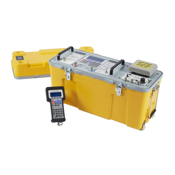
Druck ADTS 405 Service Manual INTRODUCTION There are two versions of the ADTS 405 a 19", 6U high (10½”) rack-mounted unit and a flight line unit. The ADTS 405 is a rack-mounted system and, with external pressure and vacuum supplies connected, provides measurement and control for sense and leak testing and functional tests of air data instruments, components and systems. - Page 11 Druck ADTS 405 Service Manual Figure 1-1 General view Figure 1-2 General view K171 Issue No. 1 Page 1-3...
-
Page 12: Specification
Druck ADTS 405 Service Manual SPECIFICATION Electrical power supply ............................88 to 260V a.c................................. 47 to 440Hz ADTS 405 ........................200 VA maximum ADTS 405F ........................500VA maximum Pneumatic outputs Altitude range ............................-2000ft to +80000ft Altitude accuracy Sea level ................................... ± 5ft 30,000ft .. - Page 13 Druck ADTS 405 Service Manual Figure 1-3 ADTS 405 K171 Issue No. 1 Page 1-5...
-
Page 14: Adts 405F Racks
Druck ADTS 405 Service Manual Pump Rack Electronics Rack Case Figure 1-4 ADTS 405F Racks K171 Issue No. 1 Page 1-6... -
Page 15: Description
Druck ADTS 405 Service Manual Description ADTS 405 and Electronics rack (ADTS 405F) The unit contains the pitot and static manifolds, together with all appropriate solenoid valves, pressure transducers and pneumatic output connectors. Also located in this rack are the controller PCB for each channel, computer PCB, IEEE 488 PCB key-pad and display PCB, ARINC 429 PCB and a power supply unit. - Page 16 Druck ADTS 405 Service Manual Power supply The power supply unit is located in the electronics rack enclosed in a metal casing. Output from the PSU supplies the rack with a nominal +5V and ±15V and a semi-regulated 24V supply (regulated with respect to +5V supply).
-
Page 17: Pitot And Static Controllers
Druck ADTS 405 Service Manual Pitot and Static Controllers The controller PCB is a self-contained pressure measurement control system which takes the analogue set-point from the data converter and compares it with the voltage from the transducer. A difference (error) is used to generate the pulse width modulated drive voltages for the ‘apply’ and ‘release’... - Page 18 Druck ADTS 405 Service Manual Figure 1-6 Controller PCB Schematic Figure 1-7 Ps Manifold Schematic K171 Issue No. 1 Page 1-10...
-
Page 19: Pressure Output
Druck ADTS 405 Service Manual Figure 1-8 Pt Controller PCB Schematic Pressure output The pressure generated in the manifold can be applied to the aircraft system by opening the output solenoid. The command to open the output solenoid is received over the internal communication ring. -
Page 20: Supervisor Computer And Communications
Druck ADTS 405 Service Manual Supervisor Computer and Communications The supervisor computer consists of the computer PCB located on a motherboard. The computer PCB is a self-contained microcomputer based on the 68000 microprocessor. The software is contained in two EPROM located on the computer PCB. The computer PCB provides direct communication with the hand terminal and an internal communications ring in the form of RS422 differential drivers and receivers. -
Page 21: Arinc 429 Interface (Special Order)
Druck ADTS 405 Service Manual ARINC 429 Interface (special order) The ARINC 429 interface option enables the transmitting of aeronautical and pressure parameter data to the aircraft system. It also monitors ARINC 429 data from the aircraft and shows the data on the display with the corresponding measured parameter from the ADTS 405. -
Page 22: Pump Rack
Druck ADTS 405 Service Manual Pump Rack The rack pump consists of an electric motor driving a pump and controlled by a controller PCB. The rack is cooled by an electric fan. A power supply unit produces electrical power for the motor circuit, fan and circuits to the electronics rack. -
Page 23: Hand Terminal
Druck ADTS 405 Service Manual Figure 1-11 Hand Terminal Hand terminal Note: The hand terminal is a standard component for the ADTS 405F and option B for the ADTS 405. The hand terminal has a four-key by nine-key matrix to allow single key operation for each system function. - Page 24 Druck ADTS 405 Service Manual K171 Issue No. 1 Page 1-16...
- Page 25 Druck ADTS 405 Service Manual Chapter 2 Dismantling CONTENTS Para. General ....................1 ADTS 405 and Electronics Rack (ADTS 405F) .......2 Cover ......................5 Controller PCB ..................6 Computer PCB ..................9 IEEE 488 Interface PCB ..............11 Altimeter Encoder Interface PCB ..........13 ARINC 429 Interface ................15 Front Panel ..................17...
-
Page 26: General
Druck ADTS 405 Service Manual DISMANTLING WARNING: VOLTAGES IN EXCESS OF 30 VOLTS (RMS) AC OR 50 VOLTS DC, IN CERTAIN CIRCUMSTANCES CAN BE LETHAL. CARE MUST BE TAKEN WHEN WORKING ON LIVE, EXPOSED CONDUCTORS. General Absolute cleanliness of the work area, tools and equipment must be observed. Expendable items must be discarded. -
Page 27: Ieee 488 Interface Pcb
Druck ADTS 405 Service Manual wing nut retaining clip spigot PCB retaining bar wing nut spigot IEEE 488 Interface PCB securing screws Figure 2-1 Location of the Interface PCB K0171 Issue No. 1 Page 2-3... - Page 28 Druck ADTS 405 Service Manual K0171 Issue No. 1 Page 2-4...
-
Page 29: Altimeter Encoder Interface Pcb
Druck ADTS 405 Service Manual Altimeter Encoder Interface PCB (Figure 2-1) The altimeter encoder interface PCB locates on a connector in the motherboard. Release the two clips and disconnect the ribbon connector on the top edge of the PCB. Unscrew and remove the two screws and plain washers securing PCB bracket to rear panel. - Page 30 Druck ADTS 405 Service Manual Figure 2-3 Output fitting Remove the p-clips securing the wiring looms to the manifold. Disconnect the two input pipes from the front panel and regulator. Unscrew and remove the three hexagonal socket cap-screws securing the static transducer mounting block to the main manifold.
- Page 31 Druck ADTS 405 Service Manual Controller PCB mounting detail Nylon spacer Nylon spacer Nyloc nut A.C. power connector D.C. power connector (option C) Front panel Side panel Pt Controller PCB Figure 2.4 Power Supply Unit Installation Remove the insulating sheet from the studs. Unscrew and remove the eight screws and shakeproof washers securing the PSU to the right hand side of rear chassis.
-
Page 32: Pump Rack (Adts 405F)
Druck ADTS 405 Service Manual Pump Rack (ADTS 405F) Unscrew and remove the four screws and cup washers securing the electronics rack in the case. Carefully position the electronics rack on the side of the case. Disconnect all pneumatic and electrical connections from electronics rear of the rack. -
Page 33: Psu Motor Controller Assembly
Druck ADTS 405 Service Manual Pull back the outer sleeving as necessary to gain access to the cables. Cut and remove any tyraps securing the cable loom. Disconnect the red and black cables at the terminal block under the front panel. -
Page 34: Power Supply Unit Installation
Druck ADTS 405 Service Manual Cover Power input connector Auxiliary pneumatic connectors Pump/motor assembly Bowl filter Power supply unit Motor connectors Controller PCB Figure 2.5 ADTS 405F pump rack details K0171 Issue No. 1 Page 2-10... -
Page 35: Pump Rack Details
Druck ADTS 405 Service Manual Chapter 3 Assembling CONTENTS Para. General ....................1 Pump Rack (ADTS 405F) ............... 2 PSU Motor Controller Assembly ........2 ......................5 Pump and Motor Assembly............11 Pump Front Panel ................17 ADTS 405 and Electronics Rack (ADTS 405F) .......19 Power Supply Unit ............... -
Page 36: General
Druck ADTS 405 Service Manual ASSEMBLING General Ensure all parts are clean, absolute cleanliness of the work area, tools and equipment must be observed. Pump Unit (ADTS 405F) PSU Motor Controller Assembly Secure the PSU to the side panel of the pump rack using the four screws and shakeproof washers. - Page 37 Druck ADTS 405 Service Manual K0171 Issue No. 1 Page 3-3...
-
Page 38: Pump Front Panel
Druck ADTS 405 Service Manual Locate a new bonded seal to the right-angle fitting and connect the vacuum pipe to the pump unit. Connect the pressure pipe to the bowl filter. Pump Front Panel Carefully align the front panel over the partially assembled pump unit and secure with the four countersunk screws. -
Page 39: Front Panel
Druck ADTS 405 Service Manual Display and key-pad panel Locate the key-pad and display on the front panel and secure the display with the four screws and washers. Connect the two-pin and ribbon cable connectors to the display. Front Panel Caution: Do not trap any cables between front panel and rear chassis. -
Page 40: Computer Pcb
Druck ADTS 405 Service Manual Computer PCB Note: Make sure the PCB connections are correctly aligned on the motherboard. Carefully insert the PCB into motherboard. Connect the ribbon cable connector to the top edge of the PCB. PCB Retaining bar Fit the retaining bar on the spigots make sure that the PCB are secured by the bar but not under tension. - Page 41 Druck ADTS 405 Service Manual Chapter 4 Testing CONTENTS Para. STANDARD SERVICEABILITY TEST General ..................1 Procedure ................2 FUNCTIONAL TEST Introduction ................8 Procedure ................10 IEEE 488 Interface test ..............19 IEEE 488 test Program ..............20 K171 Issue No. 1 Page 4-1...
-
Page 42: Standard Serviceability Test
Druck ADTS 405 Service Manual STANDARD SERVICEABILITY TEST General The following procedure can be used to check the functions and facilities of the ADTS 405. When one of the keys on the hand terminal or local key-pad is referred to, the term PRESS is used, e.g. Press ALT. - Page 43 Druck ADTS 405 Service Manual Key-pad Check Press the MACH key and check the display changes to show Altitude and Mach measured values. Pump unit Switch on the pump unit. Press CONTROL to go to control mode. Enter an altitude aim of 5000 ft by pressing 5, 0, 0, 0, ENTER.
-
Page 44: Functional Test
Druck ADTS 405 Service Manual FUNCTIONAL TEST Introduction This test verifies that the ADTS 405 is fully functioning, all external interfaces are tested. When one of the keys is referred to, the term PRESS is used, e.g., Press ALT. When a menu item on the display is referred to, the term SELECT is used. - Page 45 Druck ADTS 405 Service Manual Key-pad Check This verifies the hand terminal key-pad operation. Press the MACH key and check the display changes to show Altitude and Mach measured values. Press each key in turn in the order shown below and check that the hand terminal beeps on each key press.
- Page 46 Druck ADTS 405 Service Manual Vacuum leak check This section verifies that the unit is leak tight under vacuum conditions. Press LEAK MEASURE to turn the controllers off. Press RATE TIME and select WAIT 05:00, TIME 01:00. Observe that the WAITING time is shown on the display as it counts down, followed by the TIMING time.
-
Page 47: Ieee 488 Interface Test
Druck ADTS 405 Service Manual IEEE 488 interface test This section verifies IEEE 488 operation. Ensure that the IEEE 488 address of the ADTS 405 is set to 1 as follows: Hold down F1 and press SETUP to display the CONFIG menu. - Page 48 Druck ADTS 405 Service Manual K171 Issue No. 1 Page 4-8...
- Page 49 Druck ADTS 405 Service Manual Chapter 5 Calibration CONTENTS Para. General ....................1 Introduction..................2 Rate calibration ................. 8 Calibration check ................10 Procedure..................... 17 Completion ..................18 K171 Issue No. 1 Page 5-1...
-
Page 50: General
Druck ADTS 405 Service Manual CALIBRATION General For optimum calibration accuracy, the ADTS 405 should be connected to the pressure standard using metal, PTFE or high density polyethylene hoses to avoid contamination of the internal sensors. This is particularly important when using an EXTERNAL pressure source. - Page 51 Druck ADTS 405 Service Manual Rate Calibration Rate calibration should only be performed if the rate accuracy is suspect. The accuracy of measure or controlled pressures are not affected by a rate calibration. Select [RATE CAL], rate calibration takes less than two minutes.
-
Page 52: Procedure
Druck ADTS 405 Service Manual Procedure The calibration check should be carried out with the ADTS 405 in the normal operating mode. The following equipment is required: Note: Equivalent substitutes can be used. • Pressure standard accuracy ±0.01%FS absolute and gauge •... -
Page 53: Completion
Druck ADTS 405 Service Manual Completion When the calibration check is complete, repeatedly use the QUIT key to return to the first calibration screen. If necessary, carry out a rate calibration or press QUIT can be pressed again to exit calibration mode. - Page 54 Druck ADTS 405 Service Manual K171 Issue No. 1 Page 5-6...
- Page 55 Druck ADTS 405 Service Manual Chapter 6 Illustrated Parts List CONTENTS Para. Introduction..................1 Parts List ....................5 Index of Part Numbers ..............6 Illustrations fig. ADTS 405F Electronics Rack ............6-1 ADTS 405F Pump Rack ..............6-2 ADTS 405 ....................6-3 K171 Issue No. 1...
- Page 56 Druck ADTS 405 Service Manual Illustrated Parts List Introduction The purpose of this list is to itemise the parts that comprise the unit. It is intended for use in provisioning, requisitioning and storing replacement parts. In general, parts are listed in order of disassembly, and are indented to show their relationship to the next higher assembly.
- Page 57 Druck ADTS 405 Service Manual Figure 6-1 ADTS 405F Electronics Rack K171 Issue No. 1 Page 6-3...
- Page 58 Druck ADTS 405 Service Manual Figure 6-2 ADTS 405F Pump Rack K171 Issue No. 1 Page 6-4...
- Page 59 Druck ADTS 405 Service Manual Parts List Item/ Description Manufacturer's Part Number Ref. 1-1 † ADTS 405F, Air Data Test System [includes accessories] . ADTS 405F, Air Data Test System . . ADTS 405 Electronics Rack -4 † . . . Controller/manifold Assembly, 2.6 bar Pitot...
- Page 60 Druck ADTS 405 Service Manual Parts List (contd) Item/ Description Manufacturer's Part Number Ref. . .Pump Rack ADTS405F-1728-62-M0 . . .Pump/motor Assembly ADTS405F-1728-85-M0 . . .PSU Motor Controller Assembly (Mod 00) [Superseded by items 3-1A an 3-2A] -3-1A . . .PSU Pump Universal AC...
- Page 61 Druck ADTS 405 Service Manual Figure 6-3 ADTS 405 K171 Issue No. 1 Page 6-7...
- Page 62 Druck ADTS 405 Service Manual Item/ Description Manufacturer's Part Number Ref. 3-1 † ADTS 405, Air Data Test System -2 † . .Terminal, Hand [option A] ADTS405-1728-40-M0 -3 † . . . Controller/manifold Assembly ADTS405-1729-65-M0 -3.1 † ..Controller PCB, Ps [matched with item 3.3]...
- Page 63 Druck ADTS 405 Service Manual List of Accessories Item/ Description Manufacturer's Part Number Ref. 4-1 † .Accessory Bag ADTS405F-1728-39-M0 -2 † .Terminal Hand [see item 3-2] ADTS405F-1728-40-M0 -3 † .Cable Assembly 2.5M (6.5ft) [option A] ADTS405F-1728-41-M0 {standard for flight line units} -4 †...
- Page 64 Druck ADTS 405 Service Manual Index of Part Numbers Figure and item Part Number Figure and item Part Number number number ADTS405F-1533-11-M0 ADTS405-1729-71-M0 ADTS405F-1533-12-M0 1-6A ADTS405-1729-72-M0 3-5A ADTS405F-1533-13-M0 3-12 ADTS405F-1728-39-M0 ADTS405-1729-78-M0 1-12 ADTS405F-1728-40-M0 ADTS405-1729-79-M0 3-11 1-11 ADTS405F-1728-41-M0 ADTS405-1729-80-M0 3-10 ADTS405F-1728-42-M0...
Need help?
Do you have a question about the Druck ADTS 405 and is the answer not in the manual?
Questions and answers