
Related Manuals for Ahlborn ALMEMO 1036-2


Summary of Contents for Ahlborn ALMEMO 1036-2
- Page 1 ____________________________ Operating instructions ALMEMO ® 1036-2 High-precision humidity measuring instrument for Pt100 psychrometer V2.0 08.04.2015 www.ahlborn.com...
-
Page 2: Operating Controls
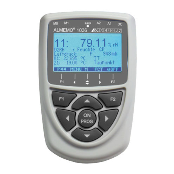
1. Operating controls 1. OPERATING CONTROLS (1) Measuring sockets M0 to M1 M0..M1 ALMEMO ® sensors M10..M31 Additional channels for humidity variables Atmospheric pressure internal M12..M32 Additional channels (2) Sleep-LED (3) Output socket A2 SD memory connector (ZA1904-SD) (4) Output socket A1 V24 interface (ZA 1909-DK5) Optic fiber (ZA 1909-DKL) USB (ZA 1919-DKU) -
Page 3: Table Of Contents
Table of Contents 2. TABLE OF CONTENTS 1. OPERATING CONTROLS................2 3. GENERAL....................5 3.1 Warranty....................5 3.2 Standard delivery................5 3.3 Waste disposal...................6 4. SAFETY INSTRUCTIONS................6 4.1 Handling batteries / rechargeable batteries correctly.....7 4.2 Special notes on use................8 5. INTRODUCTION..................8 5.1 Measuring humidity, basic principles..........8 5.2 Psychrometer..................8 5.3 Measuring instrument................9 5.4 Sensor programming...............10... - Page 4 2. Table of Contents 13.2 Maximum / minimum memory............24 13.3 Individual value memory..............24 14. SENSOR PROGRAMMING..............25 14.1 Measuring channel designation............25 14.2 Locking the sensor programming..........25 14.3 Selecting a measuring range............25 14.4 Functions of the Pt100 psychrometer FPA8363P3......26 14.4.1 Measuring ranges..............26 14.4.2 Multi-point adjustment............26 14.4.3 Smoothing by means of a sliding average......27 14.5 Functions of D6 sensors..............27...
-
Page 5: General
General 3. GENERAL We should like to congratulate you on your purchase of this new and innova- tive psychrometer; this outstanding instrument provides high-precision mea- surements for Pt100 sensors at a resolution of 0.001 K; it is thus also ideally suitable for highly accurate humidity measurement.. -
Page 6: Waste Disposal
3. General 3.3 Waste disposal The pictogram showing a waste bin crossed through means that the product is subject to European Union regu- lations on segregated waste disposal. This applies both to the product itself and to any accessories marked with the same symbol. -
Page 7: Handling Batteries / Rechargeable Batteries Correctly
Safety instructions DANGER Risk of fatal injury caused by dangerously high voltage Such risks may occur in the following circumstances : Use of the device with an unsuitable power supply and / or • in conjunction with unsuitable peripheral equipment Damage caused by electrostatic discharge or lightning •... -
Page 8: Special Notes On Use
4. Safety instructions 4.2 Special notes on use If the device is brought into the work-room from a cold environment there is a risk that • condensation might form on the electronics. In measuring operations involving ther- mocouples pronounced changes in temperature may cause substantial measuring er- rors. -
Page 9: Measuring Instrument
Psychrometer a current of air. When the power supply is connected and the integrated fan starts operating, the moistened temperature sensor will, depending on air tem- perature and humidity, cool down by a measurable amount. Based on this psy- chrometric temperature difference the water vapor’s partial pressure e´ and thus all the variables associated with atmospheric humidity can be calculated. -
Page 10: Sensor Programming
5. Introduction 5.4 Sensor programming Measuring ranges For Pt100 sensors, two high resolution measuring ranges exist: -200.000 to 560.000°C and (as an option) -200.00 to 850.00°C. The calculation of the hu- midity variables relative humidity and dew point is rounded to two decimal places. - Page 11 Measuring operation For each measuring operation the maximum value and minimum value are ac- quired and saved to memory. These values can then be displayed, printed out, or deleted from memory. Measured value memory Up to 100 measured values can be saved manually. This data can then be shown on the display or output via the interface.
-
Page 12: Putting Into Service
6. Putting into service 6. PUTTING INTO SERVICE Sensor connection Connect sensors to sockets M0 and M1 (1) see 8. Via battery or mains adapter connected at socket DC (5) Power supply see 7.1, 7.2 To switch ON Press once and release key (7) see 7.4 ON / PROG Automatic display of the measuring menu see 11,... -
Page 13: Power Supply
Power supply 7. POWER SUPPLY Power can be supplied to the measuring instrument in any of the following ways : 3 AA alkaline batteries (included in delivery) Mains adapter, 12 V, 1 A, with ALMEMO ® plug ZA 1312-NA7 Power supply cable, electrically isolated (10 to 30 VDC, 0.25 A) ZA 2690-UK Our product spectrum covers all the appropriate accessories. -
Page 14: Switching On / Off, Reinitialization
7. Power supply 7.4 Switching ON / OFF, reinitialization To switch the device ON press and release (6) located in the middle PROGr of the cursor block. The first thing to appear in the display is always the mea- suring menu. To switch OFF press and hold down the same key(s) . -
Page 15: Stationary High-Precision Psychrometer Fpa 836-3P3
Stationary high-precision psychrometer FPA 836-3P3 8.2 Stationary high-precision psychrometer FPA 836-3P3 Filling the water reservoir 1. Undo the refill screw 2. Top up the reservoir with distilled water using the squeeze bottle supplied 3. Tighten the refill screw again and perform measuring operation The water in the reservoir may in certain circumstances become contami- nated. -
Page 16: Measuring Sockets, Measuring Channels
8. Connecting sensors / transducers 2. Ensure that the humidity sensor is always sufficiently moistened. If you are unsure whether there is sufficient moisture carry out a visual inspection of both the cotton sheath and the wick itself. To moisten the wick use distilled water only. -
Page 17: Potential Separation
Potential separation 8.4 Potential separation When organizing a properly functioning measuring setup it is very important to ensure that no equalizing current flow between sensors, power supply, and pe- ripherals. All points must therefore lie at the same potential and / or any un- equal potentials that do exist must be electrically isolated. -
Page 18: Display And Keypad
1 function menu for saving values Also accessible from the measuring menu by pressing key (see 13) < FCT > AMR ALMEMO 1036-2 2 programming menus for programming the M*Sensor display © sensors and the device parameters (see 14, 16) M Meas. -
Page 19: Function Keys
Measured value display and status symbols ´µµµµµµµµµ¶ Battery voltage <3.8 V, remaining capacity <10% flashes In the data logger menu the top status bar also displays the following symbols for checking the measuring sequence : ll or © Measurement stopped or started Measuring channel scan started and data being saved Measuring channel scan started with data output via interface l©... -
Page 20: Entering Data
9. Display and keypad Help is provided by the softkey symbol <F> (for function selection) <F> To move forward to the next function press ▲ ▼ Depending on function the keys are assigned the desired meaning, ◄ ► e.g.. set measured value to zero. <ZERO>... -
Page 21: Menu Selection Screen
Menu selection screen 10. MENU SELECTION SCREEN Via the menu selection screen the following menus can be accessed : (see 9.1) M Sensor display see 11. AMR ALMEMO 1036-2 M Measuring channel list see 12. M*Sensor display © M Max./Min. individual memory M Meas. -
Page 22: Atmospheric Pressure Compensation
11. Sensor display 11.2 Atmospheric pressure compensation Certain measured variables are affected by the ambient atmospheric pressure; with a psychrometer all are affected whereas with a capacitive humidity sensor only MH and En; in both cases any pronounced deviation from standard pres- sure (1013 mbar) may lead to measuring errors. -
Page 23: Functions Menu
Measuring channel list menu 00: 23.124°C Temperature Meas.Chan. list: Max. value Measured value with maximum value 00: 23.124 °C 32.671 °C Measured value with minimum value Meas.Chan. list: Min. value 00: 23.124 °C 19.348 °C Meas.Chan. list: Range Measuring range only (also maximum 12 channels) 00: P314 °C With more than 6 measuring channels select the next page by pressing:... -
Page 24: Maximum / Minimum Memory
13. Functions menu the normal measured value is displayed again. 13.2 Maximum / minimum memory Functions menu shows not only the mea- ´´´´´´µµµµ¶ sured value with designation but also the con- 54.512 °C tinuously acquired maximum and minimum val- P314 TT, t ues for the measuring channel selected. -
Page 25: Sensor Programming
Sensor programming 14. SENSOR PROGRAMMING Since on ALMEMO ® devices all sensor programming is stored in the ALMEMO ® connector itself, the user will not normally need to reprogram each time. How- ever, with humidity sensors it is necessary sometimes to program other humid- ity ranges than those provided as standard. -
Page 26: Functions Of The Pt100 Psychrometer Fpa8363P3
14. Sensor programming select the required input channel, and then enter the range. (see 11.1) When the input for the new measuring range is confirmed all programming values for that input channel will be deleted. Function range selection RANGE: D dv <MALL>... -
Page 27: Smoothing By Means Of A Sliding Average
Functions of the Pt100 psychrometer FPA8363P3 tion can be stored in the sensor and interpolated on a linear basis for subse- quent measuring operations. 14.4.3 Smoothing by means of a sliding average When measuring temperature at a resolution of 1/1 000 °C - especially if using sensors in air - the measured value display may be unstable. -
Page 28: Correction Values
14. Sensor programming D AP B-O8 *Atm. Pressure AP in sensor FHAD36-RS 300.0... 1100.0 mbar D MH B-O4 Mixture MH, r FHAD36-RS 0.0... 6500.0 g/kg D AH B-O5 Abs. Humidity AH, dv FHAD36-RS 0.0... 596.3 g/m D VP B-O6 Vapor pressure VP, e FHAD36-RS 300... -
Page 29: Data Logger
Data logger 15. DATA LOGGER Measuring instrument ALMEMO ® 1036 can be ALMEMO 1036 made into a data logger - by fitting memory M*Sensor display © connector ZA1904SD with a micro-SD memory M Measuring points list M Max-Min, individual mem. card (available as an accessory). -
Page 30: Date And Time-Of-Day
15. Data logger 15.2 Date and time-of-day For logging data recordings a real-time clock with date and time-of-day is pro- vided. This real-time clock is buffered by means of the device battery; in the event of battery replacement date and time-of-day are lost. The first line con- tains the time-of-day on the left and the date on the right;... -
Page 31: Memory Capacity, Memory Output, Clearing The Memory
Memory capacity, memory output, clearing the memory 15.5 Memory capacity, memory output, clearing the memory While measured values are being recorded the Memory free function continu- ously displays the memory capacity still available. Selecting this function en- ables two softkeys, one for direct memory output and one for memory clearing. Function 108.4 Memory free... -
Page 32: Starting And Stopping Measuring Operations
15. Data logger When sleep mode is selected (subject to a check window being con- firmed), all necessary parameters may be configured. 15.8 Starting and stopping measuring operations A measuring operation can be started / stopped not only by pressing the appro- priate keys but also automatically by means of start time / end time or a speci - fied measuring duration. -
Page 33: Device Configuration
Device configuration 16. DEVICE CONFIGURATION Device configuration In the menu certain basic DEVICECONFIGURATION settings can be made, e.g. language and illumi- Language: English Illumination: Ø Duration: 20sec nation. The device designation can be used as Contrast: 50 % print header in log printouts. The baud rate can Baud rate: 9600 Bd be adapted for operation with external devices. -
Page 34: Device Address And Networking
16. Device configuration or 57.6, 115.2 kbaud (taking care not to exceed the maximum baud rate for the interface module). The baud rate setting is saved to the EEPROM on the inter- face module and thus applies when any other ALMEMO ®... -
Page 35: Atmospheric Pressure
Data communications The command ´f1 P18´ previously used for maximum / minimum / average val- ues with date and time-of-day has been converted for use in the table format. f1 P18 (individual channels with Mxx P18) MS;MEAS.Val;MAXVAL.;MINVAL.;AVERAGE;NUMBER;MAX-TIME;MAX-DATE;MIN-TIME;MIN-DATE 00;20,044;150,007;20,038;-;0;02:31;05.01;02:32;05.01 01;26,961;27,017;26,952;-;0;02:33;05.01;02:45;05.01 02;942,6;942,7;942,5;-;0;02:43;05.01;02:46;05.01 11;54,28;54,32;53,99;-;0;02:45;05.01;02:33;05.01 21;17,06;17,06;17,02;-;0;02:46;05.01;02:32;05.01 Certain measured value outputs in list format (commands p, P01..P03, P-04,... - Page 36 17. Option FE - function extension To enter coefficients A, B, C and resistance R0 (at 0 °C) in the Pt100 formula, first select the input channel and then determine the associated coefficients. Select the input channel Input range Enter coefficient A f1 ax.xxxxx 3.7 ...
-
Page 37: Trouble-Shooting
Trouble-shooting 18. TROUBLE-SHOOTING This measuring instrument can be configured and programmed in many differ- ent ways. It is suitable for connecting a wide variety of different sensors and peripheral equipment. Given these numerous possibilities the device may in certain circumstances not always behave quite as expected. The cause of such unexpected behavior is only very rarely a device defect;... -
Page 38: Declaration Of Conformity
19. Declaration of conformity 19. DECLARATION OF CONFORMITY Ahlborn Mess- und Regelungstechnik GmbH declares herewith that the ALMEMO ® 1036-2 device carries the CE label and complies in full with the re- quirements of EU directives relating to low voltage and to electromagnetic compatibility (EMC) (89/336/EWG). - Page 39 Technical data 1 ALMEMO ® socket for memory connector Standard equipment Display Graphics, 128 x 64 pixels, 8 rows of 4 mm Illumination 2 white LED's Operation 7 keys (4 softkeys) Memory 100 measured values in RAM, SD memory card connector Date and time-of-day Real-time clock, buffered by device battery Power supply...
-
Page 40: Product Overview
20. Annex 20.2 Product overview Order no. High-precision humidity measuring instrument with atm. pressure sensor, 3 AA alkaline batteries, mains unit ZA1312NA7, USB data cable ZA1919DKU, ® instrument case, evaluation software ALMEMO View SW5500AV and Pt100 psychrometer FPA8363P3 with mains unit, water bottle, wicks including DKD / DAkkS calibration certificate SP10362D Option FE: Erweiterte Messbereiche P314, P214, Koeffizienteneingabe OA1036FE... -
Page 41: Index
Index 20.3 Index Accessories 20.2 Atmospheric pressure 16.6 Atmospheric pressure compensation 11.2 atmospheric pressure sensors 11.2 Base value 14.5.4 batteries Battery operation Changing the wick coefficients condensation Connecting sensors contrast 16.2 Correction values 14.5.3 correctly polarized current consumption Cyclic output 15.4 Data buffering data cables... - Page 42 20. Annex Housing 20.1 Illumination 16.2 important data Individual value memory 13.3 INFO Interface, 16.3 Introduction keypad Language 16.1 Locking the sensor programming 14.2 Mains operation manual measuring channel scan 15.3 Maximum / minimum memory 13.2 Measured value display Measuring channel designation 14.1 Measuring channel list measuring channels...
- Page 43 Index replace used batteries RESET Safety instructions Scaling 14.5.4 Selecting a function Selecting a measuring channel 11.1 Selecting a measuring range 14.3 Sensor 20.2 Sensor breakage Sensor display Sensor programming 10, 25 Sensors Setting value to zero 13.1 Sleep mode 15.7 sliding average 14.4.3...
-
Page 44: Your Contact Partner
20. Annex 20.4 Your contact partner Ahlborn Mess- und Regelungstechnik GmbH Eichenfeldstraße 1-3, D-83607 Holzkirchen, Germany Tel +49(0)8024/3007-0 Fax +49(0)8024/300710 Internet http://www.ahlborn.com e-mail amr@ahlborn.com We take every possible care but the risk of inaccuracy can never be altogether excluded. We reserve the right to make technical changes without advance notice.
Need help?
Do you have a question about the ALMEMO 1036-2 and is the answer not in the manual?
Questions and answers