Siemens SITOP PSU8600 Manual
Psu8600power supply systems
Hide thumbs
Also See for SITOP PSU8600:
- Manual (420 pages) ,
- Function manual (94 pages) ,
- Manual (314 pages)
Table of Contents
Advertisement
PSU8600power supply systems
SITOP Power Supplies
PSU8600power supply systems
Manual
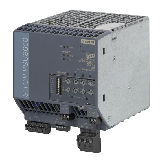
SITOP PSU8600 24 V DC/20 A/4 x 5 A
6EP3436-8MB00-2CY0
SITOP PSU8600 24 V DC/40 A/4 x 10 A
6EP3437-8MB00-2CY0
SITOP CNX8600 4 x 5 A
6EP4436-8XB00-0CY0
SITOP CNX8600 4 x 10 A
6EP4437-8XB00-0CY0
SITOP BUF8600 100 ms/40 A
6EP4297-8HB00-0XY0
SITOP BUF8600 300 ms/40 A
6EP4297-8HB10-0XY0
SITOP BUF8600 4 s/40 A
6EP4293-8HB00-0XY0
SITOP BUF8600 10 s/40 A
6EP4295-8HB00-0XY0
04.2016
A5E35883207-7-76
___________________
Overview
___________________
Safety instructions
Description, device design,
___________________
dimension drawing
Operator control at the
___________________
device
___________________
Installation and maintenance
Mounting position, mounting
___________________
clearances
___________________
Installation
Engineering and remote
___________________
access
___________________
Troubleshooting
___________________
Technical data
___________________
Safety, approvals, EMC
___________________
Environmental conditions
___________________
Applications
___________________
Environment
___________________
Service & support
1
2
3
4
5
6
7
8
9
10
11
12
13
14
Advertisement
Table of Contents


Need help?
Do you have a question about the SITOP PSU8600 and is the answer not in the manual?
Questions and answers