Table of Contents
Advertisement
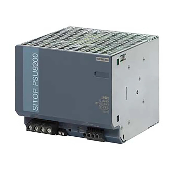
SITOP PSU8200 3ph
SITOP power supply
SITOP PSU8200 3ph
Manual
SITOP PSU8200 24 V/20 A
6EP3436-8SB00-0AY0
SITOP PSU8200 24 V/40 A
6EP1437-3BA10
11.2014
C98130-A7638-A1-2-7629
___________________
Overview
___________________
Notes on safety
Description, device design,
___________________
dimension drawing
___________________
Mounting/removing
Mounting position, mounting
___________________
clearances
___________________
Installation
___________________
Technical data
___________________
Safety, approvals, EMC
___________________
Ambient conditions
___________________
Applications
___________________
Environment
___________________
Service & Support
1
2
3
4
5
6
7
8
9
10
11
Advertisement
Table of Contents


Need help?
Do you have a question about the SITOP PSU8200 3ph and is the answer not in the manual?
Questions and answers