Table of Contents
Advertisement
Advertisement
Table of Contents

Related Manuals for D-Link DXS-1100 series


Summary of Contents for D-Link DXS-1100 series
- Page 2 Reproduction in any manner whatsoever without the written permission of D-Link Corporation is strictly forbidden. Trademarks used in this text: D-Link and the D-LINK logo are trademarks of D-Link Corporation; Microsoft and Windows are registered trademarks of Microsoft Corporation. Other trademarks and trade names may be used in this document to refer to either the entities claiming the marks and names or their products.
- Page 3 Safety Compliance Warning: Class 1 Laser Product. • EN: When using a fiber optic media expansion module, never look at the transmit laser while it is powered on. Also, never look directly at the fiber TX port and fiber cable ends when they are powered on.
-
Page 4: Table Of Contents
Table of Contents D-Link 10 Gigabit Ethernet Switch User Manual Table of Contents DXS-1100 Series 10 Gigabit Ethernet Switch ............... 錯誤! 尚未定義書籤。 User Manual ........................錯誤! 尚未定義書籤。 Table of Contents .............................. i Intended Readers.............................. 1 Terms/Usage ..............................1 Safety Instructions ............................1 General Precautions for Rack-Mountable Products .................. -
Page 5: Table Of Contents
Table of Contents D-Link 10 Gigabit Ethernet Switch User Manual Reboot System ............................26 Tool Bar > Wizard ............................26 Tool Bar > Online Help ..........................27 Function Tree ............................... 28 Device Information ........................... 28 System > System Information Settings ....................29 System >... - Page 6 Table of Contents D-Link 10 Gigabit Ethernet Switch User Manual L2 Features > VLAN > Voice VLAN > Voice VLAN Global ..............58 L2 Features > VLAN > Voice VLAN > Voice VLAN Port ................59 L2 Features > VLAN > Voice VLAN > Voice VLAN OUI ................59 L2 Features >...
- Page 7 Table of Contents D-Link 10 Gigabit Ethernet Switch User Manual Security > SSL > SSL Global Settings ..................... 98 Security > SSL > Crypto PKI Trustpoint ....................100 Security > SSL > SSL Service Policy ..................... 100 OAM > Cable Diagnostics ........................101 Monitoring >...
-
Page 8: Intended Readers
Gigabit Ethernet Switch User Manual Intended Readers This guide provides instructions to install the D-Link 10 Gigabit Ethernet Switch DXS-1100-10TS, and DXS- 1100-16TC, how to configure Web-based Management step-by-step. NOTE: The model you have purchased may appear slightly different from the illustrations shown in the document. -
Page 9: General Precautions For Rack-Mountable Products
Product Introduction D-Link 10 Gigabit Ethernet Switch User Manual An object has fallen into the product. The product has been exposed to water. The product has been dropped or damaged. The product does not operate correctly when you follow the operating instructions. -
Page 10: Protecting Against Electrostatic Discharge
Product Introduction D-Link 10 Gigabit Ethernet Switch User Manual • Systems are considered to be components in a rack. Thus, "component" refers to any system as well as to various peripherals or supporting hardware. • Before working on the rack, make sure that the stabilizers are secured to the rack, extended to the floor, and that the full weight of the rack rests on the floor. -
Page 11: Product Introduction
D-Link Green Technology includes a number of innovations to reduce energy consumption on DXS-1100 series such as shutting down a port, or turning off some LED indicators, or adjusting the power usage according to the Ethernet cable connected to it. -
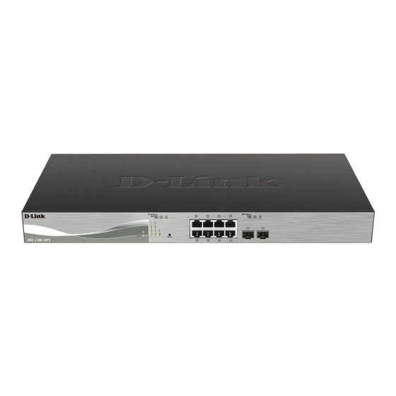
Page 12: Dxs-1100-10Ts
1 Product Introduction D-Link 10 Gigabit Ethernet Switch User Manual DXS-1100-10TS The DXS-1100-10TS 10 Gigabit Ethernet Switch supports the following ports: • Eight 100/1000/10000Mbps copper Ethernet ports. • Two 1/10Gbps SFP+ module ports. Front Panel Figure 1.1 – DXS-1100-10TS Front Panel Power LED : The Power LED lights up when the Switch is connected to a power source. -
Page 13: Dxs-1100-16Tc
1 Product Introduction D-Link 10 Gigabit Ethernet Switch User Manual Fans: Switches in this series have a built-in temperature sensor that will measure the switch’s internal temperature and then automatically adjust the speed of the fans to either high-speed or low-speed. - Page 14 1 Product Introduction D-Link 10 Gigabit Ethernet Switch User Manual ventilation. Without proper heat dissipation and air circulation, system components might overheat which could lead to system failure or even severely damaged components. Rack-mounting Screw Holes: The screw holes are used for attach mounting brackets when installing the Switch to the rack.
-
Page 15: Hardware Installation
Screws and two mounting brackets One Multi-lingual Getting Started Guide One CD with Web UI Reference Guide, Getting Started Guide, and D-Link Network Assistant User Guide. If any item is found missing or damaged, please contact the local reseller for replacement. - Page 16 2 Hardware Installation D-Link 10 Gigabit Ethernet Switch User Manual Figure 2.2 – Attach the mounting brackets to the Switch Then, use the screws provided with the equipment rack to mount the switch in the rack. Figure 2.3 – Mount the Switch in the rack or chassis...
-
Page 17: Step 3: Plugging In The Ac Power Cord With Power Cord Retainer
2 Hardware Installation D-Link 10 Gigabit Ethernet Switch User Manual E) Reliable Earthing - Reliable earthing of rack-mounted equipment should be maintained. Particular attention should be given to supply connections other than direct connections to the branch circuit (e.g. use of power strips)."... - Page 18 2 Hardware Installation D-Link 10 Gigabit Ethernet Switch User Manual Figure 2.6 – Slide the Retainer through the Tie Wrap D) Circle the tie of the Retainer around the power cord and into the locker of the Retainer. Figure 2.7 – Circle around the power cord...
-
Page 19: Power Failure
2 Hardware Installation D-Link 10 Gigabit Ethernet Switch User Manual Figure 2.8 – Secure the power cord F) Users may now connect the AC power cord to an electrical outlet (preferably one that is grounded and surge protected). Figure 2.9 – Plugging the switch into an outlet Power Failure As a precaution, the switch should be unplugged in case of power failure. -
Page 20: Getting Started
This chapter introduces the management interface of the Switch. Management Options The D-Link Switch can be managed through any port on the device by using the Web-based Management. Each switch must be assigned its own IP Address, which is used for communication with the Web-Based Management or a SNMP network manager. -
Page 21: Smart Wizard
D-Link smart switches and D-Link Discover Protocol (DDP) supported devices (for a list of supported models, refer to the D-Link Network Assistant (DNA) User Guide), that are in the same subnet as the PC, collect traps and log messages, and provide quick access to basic configurations of the switch. - Page 22 D-Link 10 Gigabit Ethernet Switch User Manual NOTE: Please be sure to uninstall any existing DNA from your PC before installing the latest DNA. For detailed explanations of the DNA functions, please refer to D-Link Network Assistant (DNA) User Guide.
-
Page 23: Configuration
4 Configuration D-Link 10 Gigabit Ethernet Switch User Manual Configuration The features and functions of the Switch can be configured for optimum use through the Web-based Management Utility. Smart Wizard Configuration After a successful login, the Smart Wizard will guide you through essential settings of the Switch. If you do not plan to change anything, click Exit to leave the Wizard and enter the Web Interface. -
Page 24: User Accounts Settings
4 Configuration D-Link 10 Gigabit Ethernet Switch User Manual User Accounts Settings Type the desired new username in the User Name field and select the Privilege between User and Administrator. Select Password Type among None, Plain Text and Encrypted, and type the desired password in the Password field. -
Page 25: Snmp
4 Configuration D-Link 10 Gigabit Ethernet Switch User Manual SNMP The SNMP Setting allows you to quickly enable or disable the SNMP function. The default SNMP Setting is Disabled. Click Enabled and then click Apply & Save to make it effective. -
Page 26: Web-Based Management
Configuration Screen. The main configuration screen will show the current status of your Switch by clicking the model name on top of the function tree. Finally, by clicking the D-Link logo at the upper-left corner of the screen you will be redirected to the D-Link website. -
Page 27: Tool Bar > Save Menu
4 Configuration D-Link 10 Gigabit Ethernet Switch User Manual Tool Bar > Save Menu The Save Menu provides the Save Configuration function. Figure 4.5 – Save Menu Save Configuration Select to save the entire configuration changes you have made to the device to switch’s non-volatile RAM. - Page 28 4 Configuration D-Link 10 Gigabit Ethernet Switch User Manual Figure 4.9 – Tools Menu > Firmware Upgrade and Backup > Firmware Upgrade from HTTP The fields that can be configured are described below: Source File: Click Browse to browse your inventories for a saved firmware file.
-
Page 29: Configuration Restore And Backup
4 Configuration D-Link 10 Gigabit Ethernet Switch User Manual Click Backup to save the firmware to your disk. Firmware Backup to TFTP This window is used to back up the firmware to TFTP. Figure 4.12 – Tools Menu > Firmware Upgrade and Backup > Firmware Backup to TFTP The fields that can be configured are described below: TFTP Server IP: Backup the firmware to a remote TFTP server. - Page 30 4 Configuration D-Link 10 Gigabit Ethernet Switch User Manual Destination File: Enter the destination filename and path where the configuration file should be stored on the Switch. This field can be up to 64 characters long. Select the running-config option to restore and overwrite the running configuration file on the Switch.
-
Page 31: Log Backup
4 Configuration D-Link 10 Gigabit Ethernet Switch User Manual Figure 4.17 – Tools Menu > Configure Restore and Backup > Configuration Backup to TFTP The fields that can be configured are described below: TFTP Server IP: Back up the configuration from a remote TFTP server. Specify TFTP server IP address with IPv4 or IPv6 address. -
Page 32: Ping
4 Configuration D-Link 10 Gigabit Ethernet Switch User Manual Figure 4.20 – Tools Menu > Log Backup > Log Backup to TFTP The fields that can be configured are described below: TFTP Server IP: Back up the log from a remote TFTP server. Specify TFTP server IP address with IPv4 or IPv6 address. -
Page 33: Reset
4 Configuration D-Link 10 Gigabit Ethernet Switch User Manual Figure 4.22 –Ping Result Click Stop to halt the Ping Test. Click Back to return to the IPv4 or IPv6 Ping section. Reset Provide a safe reset option for the Switch. -
Page 34: Tool Bar > Online Help
Tool Bar > Online Help The Online Help provides two ways of online support: D-Link Support Site will lead you to the D-Link website where you can find online resources such as updated firmware images; User Guide can offer an immediate reference for the feature definition or configuration guide. -
Page 35: Function Tree
4 Configuration D-Link 10 Gigabit Ethernet Switch User Manual Function Tree All configuration options on the Switch are accessed through the Function Tree. Click the setup item that you want to configure. The following sections provide more detailed description of each feature and function. -
Page 36: System > System Information Settings
4 Configuration D-Link 10 Gigabit Ethernet Switch User Manual Figure 4.27 – Device Information System > System Information Settings The System Information Settings allows the user to configure a System Name, System Location, and System Contact to aid in defining the Switch. -
Page 37: System > Port Configuration > Port Settings
4 Configuration D-Link 10 Gigabit Ethernet Switch User Manual The fields that can be configured are described below: Fan Trap: Enable or disable the fan trap state for warning fan event (fan failed or fan recover). Thermal: Select the thermal sensor ID. -
Page 38: System > Port Configuration > Port Status
4 Configuration D-Link 10 Gigabit Ethernet Switch User Manual Flow Control: Select to either turn flow control On or Off here. Ports configured for full-duplex use 802.3x flow control, half-duplex ports use back-pressure flow control, and Auto ports use an automatic selection of the two. -
Page 39: System > Port Configuration > Jumbo Frame
4 Configuration D-Link 10 Gigabit Ethernet Switch User Manual Figure 4.32 – System > Port Configuration > Error Disable Settings The fields that can be configured are described below: Asserted: Select this option to enable or disable the notifications when entering into the error disabled state. -
Page 40: System > System Log > System Log Settings
4 Configuration D-Link 10 Gigabit Ethernet Switch User Manual Figure 4.33 – System > Port Configuration > Jumbo Frame The fields that can be configured are described below: From Port / To Port: Select the appropriate port range used for the configuration here. -
Page 41: System > System Log > System Log Discriminator Settings
4 Configuration D-Link 10 Gigabit Ethernet Switch User Manual Write Delay: Enter the interval for periodic writing of the logging buffer to FLASH. This value must be between 0 and 65535 seconds. By default, this value is 300 seconds. Tick Infinite to disable the write delay feature. -
Page 42: System > System Log > System Log
4 Configuration D-Link 10 Gigabit Ethernet Switch User Manual UDP Port: Specifies the UDP port to which the server logs are sent. This value must be 514, or between 1024 and 65535. The default value is 514. Severity: Select the severity value of the type of information that will be logged. Options to choose from are 0 (Emergencies), 1 (Alerts), 2 (Critical), 3 (Errors), 4 (Warnings), 5 (Notifications), 6 (Informational), and 7 (Debugging). -
Page 43: System > Time And Sntp > Time Zone Settings
4 Configuration D-Link 10 Gigabit Ethernet Switch User Manual services, organize the SNTP subnet of servers and clients, and adjust the system clock in each participant. This window is used to configure the time settings for the Switch. Figure 4.39 – System > Time and SNTP > Clock Settings The fields that can be configured are described below: Time (HH MM:SS): Enter the current time in hours, minutes, and seconds. -
Page 44: System > Time And Sntp > Sntp Settings
4 Configuration D-Link 10 Gigabit Ethernet Switch User Manual Date Setting - Select to configure the summer time that should start and end on the specified date of the specified month. Time Zone: Select to specify your local time zone’s offset from Coordinated Universal Time (UTC). -
Page 45: System > Time Range
4 Configuration D-Link 10 Gigabit Ethernet Switch User Manual Click Delete to remove the specified entry. System > Time Range This window is used to view and configure the time range settings. Figure 4.42 – System > Time Range The fields that can be configured are described below: Range Name: Enter the name of the time range. -
Page 46: Management > Password Encryption
4 Configuration D-Link 10 Gigabit Ethernet Switch User Manual The fields that can be configured are described below: User Name: Enter the user account name here. This name can be up to 32 characters long. Privilege: Select the privilege level for this account. -
Page 47: Management > Snmp > Snmp Linkchange Trap Settings
4 Configuration D-Link 10 Gigabit Ethernet Switch User Manual Figure 4.46 – Management > SNMP > SNMP Global Settings The fields that can be configured are described below: SNMP Global State: Enable or disable the SNMP feature. SNMP Response Broadcast Request: Enable or disable the server to response to broadcast SNMP GetRequest packets. -
Page 48: Management > Snmp > Snmp View Table Settings
4 Configuration D-Link 10 Gigabit Ethernet Switch User Manual Figure 4.47 – Management > SNMP > SNMP Linkchange Trap Settings The fields that can be configured are described below: From Port / To Port: Select the appropriate port range used for the configuration here. -
Page 49: Management > Snmp > Snmp Community Table Settings
4 Configuration D-Link 10 Gigabit Ethernet Switch User Manual Subtree OID: Enter the Object Identifier (OID) Subtree for the view. The OID identifies an object tree (MIB tree) that will be included or excluded from access by an SNMP manager. -
Page 50: Management > Snmp > Snmp Engine Id Local Settings
4 Configuration D-Link 10 Gigabit Ethernet Switch User Manual Figure 4.50 – Management > SNMP > SNMP Group Table Settings The fields that can be configured are described below: Group Name: Enter the group name of a maximum of 32 characters. The syntax is general string that does not allow space. -
Page 51: Management > Snmp > Snmp User Table Settings
4 Configuration D-Link 10 Gigabit Ethernet Switch User Manual Click Apply to accept the changes made. Management > SNMP > SNMP User Table Settings Figure 4.52 – Management > SNMP > SNMP User Table Settings The fields that can be configured are described below: User Name: Enter an alphanumeric string of up to 32 characters. -
Page 52: Management > Rmon > Rmon Global Settings
4 Configuration D-Link 10 Gigabit Ethernet Switch User Manual Figure 4.53 – Management > SNMP > SNMP Host Table Settings The fields that can be configured are described below: Host IPv4 Address: Enter the IPv4 address of the SNMP notification host. -
Page 53: Management > Rmon > Rmon Statistics Settings
4 Configuration D-Link 10 Gigabit Ethernet Switch User Manual Management > RMON > RMON Statistics Settings This window is used to configure and display the RMON statistics on the specified port. Figure 4.55 – Management > RMON > RMON Statistics Settings The fields that can be configured are described below: Port: Select to choose the port. -
Page 54: Management > Rmon > Rmon Alarm Settings
4 Configuration D-Link 10 Gigabit Ethernet Switch User Manual Bucket Number: Enter Specifies the number of buckets specified for the RMON collection history group of statistics. The range is from 1 to 65535. The default value is 50. Interval: Enter the time in seconds in each polling cycle. The range is from 1 to 3600. -
Page 55: Management > Rmon > Rmon Event Settings
4 Configuration D-Link 10 Gigabit Ethernet Switch User Manual Click Add to add a new entry based on the information entered. Click Delete to remove the specified entry. Enter a page number and click Go to navigate to a specific page when multiple pages exist. -
Page 56: Management > Session Timeout
4 Configuration D-Link 10 Gigabit Ethernet Switch User Manual Figure 4.62 – Management > Web The fields that can be configured are described below: Port: Enter the TCP port number used for Web-based management of the Switch. The “well-known” TCP port for the Web-based protocol is 80. -
Page 57: Management > D-Link Discovery Protocol
Management > D-Link Discovery Protocol This window is used to configure and display D-Link Discovery Protocol (DDP). -
Page 58: L2 Features > Fdb > Static Fdb > Unicast Static Fdb
Figure 4.67 – Management > D-Link Discovery Protocol The fields that can be configured are described below: D-Link Discovery Protocol State: Enable or disable DDP global state. Report Timer: Select the interval in seconds between two consecutive DDP report messages. Options to choose from are 30, 60, 90,120, and Never. -
Page 59: L2 Features > Fdb > Static Fdb > Multicast Static Fdb
4 Configuration D-Link 10 Gigabit Ethernet Switch User Manual MAC Address: Enter the MAC address to which packets will be statically forwarded or dropped. This must be a unicast MAC address. Click Apply to accept the changes made. Click Delete All to delete all the entries found in the display table. -
Page 60: L2 Features > Fdb > Mac Address Table
4 Configuration D-Link 10 Gigabit Ethernet Switch User Manual Figure 4.71 – L2 Features > FDB > MAC Address Table Settings (MAC Address Learning) The fields that can be configured are described below: From Port / To Port: Select the range of ports that will be used for this configuration here. -
Page 61: L2 Features > Fdb > Mac Notification
4 Configuration D-Link 10 Gigabit Ethernet Switch User Manual Click Find to locate a specific entry based on the information entered. Click Clear All to clear all dynamic MAC addresses. Click View All to display all the MAC addresses recorded in the MAC address table. -
Page 62: L2 Features > Vlan > Asymmetric Vlan
4 Configuration D-Link 10 Gigabit Ethernet Switch User Manual simplify network management by allowing users to move devices to a new VLAN without having to change any physical connections. The IEEE 802.1Q VLAN Settings window provides powerful VID management functions. The original settings have the VID as 1, VLAN Name as default, and all ports as Untagged. -
Page 63: L2 Features > Vlan > Auto Surveillance Vlan > Auto Surveillance Properties
4 Configuration D-Link 10 Gigabit Ethernet Switch User Manual Figure 4.76 – L2 Features > VLAN > VLAN Interface Click View Detail to view more detailed information about the VLAN on the specific interface. Click Edit to re-configure the specific entry. -
Page 64: L2 Features > Vlan > Auto Surveillance Vlan > Mac Settings And Surveillance Device
4 Configuration D-Link 10 Gigabit Ethernet Switch User Manual Figure 4.78 – L2 Features > VLAN > Auto Surveillance VLAN> Auto Surveillance Properties The fields that can be configured are described below: Surveillance VLAN: Enable or disable the surveillance VLAN state Surveillance VLAN ID: Enter the surveillance VLAN ID. -
Page 65: L2 Features > Vlan > Voice Vlan > Voice Vlan Global
4 Configuration D-Link 10 Gigabit Ethernet Switch User Manual Figure 4.79 – L2 Features > VLAN > Auto Surveillance VLAN> MAC Settings and Surveillance Device (User-defined MAC Settings) The fields that can be configured are described below: Component Type: Select the surveillance component type. Options to choose from are Video Management Server, VMS Client/Remote Viewer, Video Encoder, Network Storage, and Other IP Surveillance Device. -
Page 66: L2 Features > Vlan > Voice Vlan > Voice Vlan Port
4 Configuration D-Link 10 Gigabit Ethernet Switch User Manual The fields that can be configured are described below: Voice VLAN State: Enable or disable voice VLAN. Voice VLAN ID: Enter the voice VLAN ID. The value is range from 2 to 4094. -
Page 67: L2 Features > Vlan > Voice Vlan > Voice Vlan Device
4 Configuration D-Link 10 Gigabit Ethernet Switch User Manual Figure 4.83 – L2 Features > VLAN > Voice VLAN > Voice VLAN OUI The fields that can be configured are described below: OUI Address: Enter the OUI MAC address. Mask: Enter the OUI MAC address matching bitmask. -
Page 68: L2 Features > Stp > Stp Port Settings
4 Configuration D-Link 10 Gigabit Ethernet Switch User Manual settings configured for STP are also used for RSTP. This section introduces some new Spanning Tree concepts and illustrates the main differences between the two protocols. By default, Spanning Tree Protocol is Disabled. If enabled, the Switch will listen for BPDU packets and its accompanying Hello packet. - Page 69 4 Configuration D-Link 10 Gigabit Ethernet Switch User Manual An STP Group spanning tree works in the same way as the switch-level spanning tree, but the root bridge concept is replaced with a root port concept. A root port is a port of the group that is elected based on port priority and port cost, to be the connection to the network for the group.
-
Page 70: L2 Features > Stp > Stp Global Information
4 Configuration D-Link 10 Gigabit Ethernet Switch User Manual because those bridges are not under the full control of the administrator. When a port is set to the TCN filter mode, the TC event received by the port will be ignored. By default, this option is Disabled. -
Page 71: L2 Features > Link Aggregation
4 Configuration D-Link 10 Gigabit Ethernet Switch User Manual Figure 4.90 – L2 Features > Loopback Detection The fields that can be configured are described below: Loopback Detection State: Enable or disable loopback detection. The default is Disabled. Mode: The loopback detection mode is Port-based. - Page 72 4 Configuration D-Link 10 Gigabit Ethernet Switch User Manual Figure 4.91 – Example of Port Trunk Group The Switch treats all ports in a trunk group as a single port. Data transmitted to a specific host (destination address) will always be transmitted over the same port in a trunk group. This allows packets in a data stream to arrive in the same order they were sent.
-
Page 73: L2 Features > L2 Multicast Control> Igmp Snooping > Igmp Snooping Settings
4 Configuration D-Link 10 Gigabit Ethernet Switch User Manual NOTE: If any ports within the trunk group become disconnected, packets intended for the disconnected port will be load shared among the other linked ports of the link aggregation group. This window is used to view and configure the link aggregation settings. - Page 74 4 Configuration D-Link 10 Gigabit Ethernet Switch User Manual Figure 4.93 – L2 Features > L2 Multicast Control > IGMP Snooping > IGMP Snooping Settings The fields that can be configured are described below: Global State: Enable or disable IGMP snooping global state.
-
Page 75: L2 Features > L2 Multicast Control> Igmp Snooping > Igmp Snooping Groups Settings
4 Configuration D-Link 10 Gigabit Ethernet Switch User Manual After clicking Modify or Edit in IGMP Snooping Settings window, the following window will appear. Figure 4.95 – L2 Features > L2 Multicast Control > IGMP Snooping > IGMP Snooping VLAN Settings The fields that can be configured are described below: Minimum Version: Select the minimum version of IGMP hosts that is allowed on the VLAN. -
Page 76: L2 Features > L2 Multicast Control> Igmp Snooping > Igmp Snooping Mrouter Settings
4 Configuration D-Link 10 Gigabit Ethernet Switch User Manual Figure 4.96 – L2 Features > L2 Multicast Control > IGMP Snooping > IGMP Snooping Groups Settings The fields that can be configured are described below: VID: Enter a VLAN ID of the multicast group. -
Page 77: L2 Features > L2 Multicast Control> Igmp Snooping > Igmp Snooping Statistics Settings
4 Configuration D-Link 10 Gigabit Ethernet Switch User Manual Port - Select to have the configured ports to be static multicast router ports. Forbidden Port - Select to have the configured ports not to be multicast router ports. From Port / To Port: Select the appropriate port range used for the configuration here. - Page 78 4 Configuration D-Link 10 Gigabit Ethernet Switch User Manual multicast traffic, it adds the port directly attached to it into the correct IPv6 multicast table, and begins the process of forwarding multicast traffic to that port. This entry in the multicast routing table records the port, the VLAN ID, and the associated multicast IPv6 multicast group address, and then considers this port to be an active listening port.
- Page 79 4 Configuration D-Link 10 Gigabit Ethernet Switch User Manual Click Edit to re-configure the specific entry. Enter a page number and click Go to navigate to a specific page when multiple pages exist. After clicking Show Detail, the following window will appear.
-
Page 80: L2 Features > L2 Multicast Control> Mld Snooping > Mld Snooping Groups Settings
4 Configuration D-Link 10 Gigabit Ethernet Switch User Manual The fields that can be configured are described below: Minimum Version: Select the minimum version of MLD hosts that is allowed on the VLAN. Querier State: Enable or disable the querier state. -
Page 81: L2 Features > L2 Multicast Control> Mld Snooping > Mld Snooping Mrouter Settings
4 Configuration D-Link 10 Gigabit Ethernet Switch User Manual L2 Features > L2 Multicast Control> MLD Snooping > MLD Snooping Mrouter Settings This window is used to configure the specified interface(s) as the router ports or forbidden to be IPv6 multicast router ports on the VLAN interface on the Switch. -
Page 82: L2 Features > L2 Multicast Control> Multicast Filtering
4 Configuration D-Link 10 Gigabit Ethernet Switch User Manual From Port / To Port: Select the appropriate port range used for the configuration here. This is available when Port is selected in the Statistics list. Find Type: Select the interface type. Options to choose from are VLAN and Port. -
Page 83: L2 Features > Lldp > Lldp Global Settings
4 Configuration D-Link 10 Gigabit Ethernet Switch User Manual L2 Features > LLDP > LLDP Global Settings LLDP (Link Layer Discovery Protocol) provides IEEE 802.1AB standards-based method for switches to advertise themselves to neighbor devices, as well as to learn about neighbor LLDP devices. SNMP utilities can learn the network topology by obtaining the MIB information in each LLDP device. -
Page 84: L2 Features > Lldp > Lldp Management Address List
4 Configuration D-Link 10 Gigabit Ethernet Switch User Manual Figure 4.107 – L2 Features > LLDP > LLDP Port Settings The fields that can be configured are described below: From Port / To Port: Select the appropriate port range used for the configuration here. -
Page 85: L2 Features > Lldp > Lldp Basic Tlvs Settings
4 Configuration D-Link 10 Gigabit Ethernet Switch User Manual The fields that can be configured are described below: All/IPv4/IPv6: Select the subtype. Options to choose from are All, IPv4 and IPv6. Click Find to locate a specific entry based on the information entered. -
Page 86: L2 Features > Lldp > Lldp Dot3 Tlvs Settings
4 Configuration D-Link 10 Gigabit Ethernet Switch User Manual Figure 4.110 – L2 Features > LLDP > LLDP Dot1 TLVs Settings The fields that can be configured are described below: From Port / To Port: Select the appropriate port range used for the configuration here. -
Page 87: L2 Features > Lldp > Lldp-Med Port Settings
4 Configuration D-Link 10 Gigabit Ethernet Switch User Manual Figure 4.111 – L2 Features > LLDP > LLDP Dot3 TLVs Settings The fields that can be configured are described below: From Port / To Port: Select the appropriate port range used for the configuration here. -
Page 88: L2 Features > Lldp > Lldp Statistics Information
4 Configuration D-Link 10 Gigabit Ethernet Switch User Manual Figure 4.112 – L2 Features > LLDP > LLDP-MED Port Settings The fields that can be configured are described below: From Port / To Port: Select the appropriate port range used for the configuration here. -
Page 89: L2 Features > Lldp > Lldp Local Port Information
4 Configuration D-Link 10 Gigabit Ethernet Switch User Manual Figure 4.113 – L2 Features > LLDP > LLDP Statistics Information The fields that can be configured are described below: Port: Select the port number that will be displayed. Click Clear Counter to clear the counter information for the statistics displayed. - Page 90 4 Configuration D-Link 10 Gigabit Ethernet Switch User Manual Figure 4.114 – L2 Features > LLDP > LLDP Local Port Information The fields that can be configured are described below: Port: Select the port number that will be displayed. Click Find to locate a specific entry based on the information entered.
-
Page 91: L2 Features > Lldp > Lldp Neighbor Port Information
4 Configuration D-Link 10 Gigabit Ethernet Switch User Manual Figure 4.116 – L2 Features > LLDP > LLDP Local Port Information (Show Detail) L2 Features > LLDP > LLDP Neighbor Port Information This window is used to display the information learned from the neighbors. The switch receives packets from a remote station but is able to store the information as local. -
Page 92: L3 Features > Ipv6 Interface
4 Configuration D-Link 10 Gigabit Ethernet Switch User Manual Get IP From: Select the get IP from option here. Options to choose from are Static, DHCP, and BOOTP. When the Static option is selected, users can enter the IPv4 address of this interface manually in the fields provided. -
Page 93: L3 Features > Ipv6 Neighbor
4 Configuration D-Link 10 Gigabit Ethernet Switch User Manual Click Apply to accept the changes made for each individual section. After clicking the Interface IPv6 Address tab, the following page will appear. Figure 4.121 – L3 Features > IPV6 Interface (Interface IPv6 Address) Click Delete to delete the specified entry. -
Page 94: L3 Features > Ipv6 Route Table
4 Configuration D-Link 10 Gigabit Ethernet Switch User Manual Click Clear All to clear all the information in this table. Click Delete to remove the specific entry. Enter a page number and click Go to navigate to a specific page when multiple pages exist. -
Page 95: Qos > Basic Settings > Queue Settings
4 Configuration D-Link 10 Gigabit Ethernet Switch User Manual Figure 4.126 – QoS > Basic Settings > Port Scheduler Method The fields that can be configured are described below: From Port / To Port: Select the appropriate port range used for the configuration here. -
Page 96: Qos > Basic Settings > Cos To Queue Mapping
4 Configuration D-Link 10 Gigabit Ethernet Switch User Manual Figure 4.127 – QoS > Basic Settings > Queue Settings The fields that can be configured are described below: From Port / To Port: Select the appropriate port range used for the configuration here. -
Page 97: Qos > Basic Settings > Port Rate Limiting
4 Configuration D-Link 10 Gigabit Ethernet Switch User Manual The fields that can be configured are described below: Queue ID: Select the queue ID that will be mapped to the corresponding CoS value. Options to choose from are 0 to 7. -
Page 98: Qos > Advanced Settings > Dscp Cos Mapping
4 Configuration D-Link 10 Gigabit Ethernet Switch User Manual Figure 4.130 – QoS > Advanced Settings > Port Trust State The fields that can be configured are described below: From Port / To Port: Select the appropriate port range used for the configuration here. -
Page 99: Security > Port Security > Port Security Global Settings
4 Configuration D-Link 10 Gigabit Ethernet Switch User Manual Figure 4.131 – QoS > Advanced Settings > DSCP CoS Mapping The fields that can be configured are described below: From Port / To Port: Select the appropriate port range used for the configuration here. -
Page 100: Security > Port Security > Port Security Port Settings
4 Configuration D-Link 10 Gigabit Ethernet Switch User Manual Trap State: Enable or disable port security traps on the Switch. Trap Rate: Enter the number of traps per second. The range is from 0 to 1000. The default value 0 indicates an SNMP trap to be generated for every security violation. -
Page 101: Security > Port Security > Port Security Address Entries
4 Configuration D-Link 10 Gigabit Ethernet Switch User Manual Aging Type: Select the aging type here. Options to choose from are Absolute and Inactivity. Absolute - All the secure addresses on this port age out exactly after the time specified and is removed from the secure address list. -
Page 102: Security > Safeguard Engine Settings
4 Configuration D-Link 10 Gigabit Ethernet Switch User Manual The fields that can be configured are described below: From Port / To Port: Select the appropriate port range used for the configuration here. Gateway IP: Enter the gateway’s IP address used here. -
Page 103: Security > Storm Control
4 Configuration D-Link 10 Gigabit Ethernet Switch User Manual The traffic segmentation member list can be comprised of different interface types, for example port and port-channel in the same forwarding domain. If the interfaces specified by the command include a port- channel, all the member ports of this port-channel will be included in the forwarding domain. -
Page 104: Security > Dos Attack Prevention Settings
4 Configuration D-Link 10 Gigabit Ethernet Switch User Manual The fields that can be configured are described below: Trap State: Select the storm control trap option here. Options to choose from are None, Storm Occur, Storm Clear, and Both. None - no traps will be sent. -
Page 105: Security > Ssl > Ssl Global Settings
4 Configuration D-Link 10 Gigabit Ethernet Switch User Manual • Land Attack: This type of attack involves IP packets where the source and destination address are set to the address of the target device. It may cause the target device to reply to itself continuously. - Page 106 4 Configuration D-Link 10 Gigabit Ethernet Switch User Manual cryptographic parameters, specific encryption algorithms and key sizes to be used for an authentication session and consists of three levels: • Key Exchange: The first part of the Cipher suite string specifies the public key algorithm to be used.
-
Page 107: Security > Ssl > Crypto Pki Trustpoint
4 Configuration D-Link 10 Gigabit Ethernet Switch User Manual File Select: Select the file type that will be loaded here. Options to choose from are Certificate and Private Key. After selecting the file type, browse to the appropriate file, located on the local computer, by pressing the Browse button. -
Page 108: Oam > Cable Diagnostics
4 Configuration D-Link 10 Gigabit Ethernet Switch User Manual Figure 4.143 – Security > SSL > SSL Service Policy The fields that can be configured are described below: Policy Name: Enter the SSL service policy name here. This name can be up to 32 characters long. -
Page 109: Monitoring > Utilization > Port Utilization
4 Configuration D-Link 10 Gigabit Ethernet Switch User Manual From Port / To Port: Select the appropriate port range used for the configuration here. Click Test to test the specific port. Click Clear All to clear all the information in this table. - Page 110 4 Configuration D-Link 10 Gigabit Ethernet Switch User Manual Figure 4.146 – Monitoring > Statistics > Port The fields that can be configured are described below: From Port / To Port: Select the appropriate port range used for the configuration here.
-
Page 111: Monitoring > Statistics > Port Counters
4 Configuration D-Link 10 Gigabit Ethernet Switch User Manual Figure 4.147 – Monitoring > Statistics > Port Detail Click Back to return to the previous window. Click Refresh to refresh the display table. Monitoring > Statistics > Port Counters This window is used to display port counter statistics. - Page 112 4 Configuration D-Link 10 Gigabit Ethernet Switch User Manual Figure 4.148 – Monitoring > Statistics > Port Counters The fields that can be configured are described below: From Port / To Port: Select the appropriate port range used for the configuration here.
-
Page 113: Monitoring > Statistics > Counters
4 Configuration D-Link 10 Gigabit Ethernet Switch User Manual Click Back to return to the previous window. Click Refresh to refresh the display table. Monitoring > Statistics > Counters This window is used to display all port counters, and clear the port counters of the specified or all ports. -
Page 114: Monitoring > Mirror Settings
4 Configuration D-Link 10 Gigabit Ethernet Switch User Manual Figure 4.151 – Monitoring > Statistics > Port Counters Detail Click Back to return to the previous window. Click Refresh to refresh the display table. Monitoring > Mirror Settings This window is used to view and configure the mirror feature’s settings. The Switch allows users to copy frames transmitted and received on a port and redirect the copies to another port. -
Page 115: Monitoring > Device Environment
4 Configuration D-Link 10 Gigabit Ethernet Switch User Manual The fields that can be configured are described below: Session Number: Select the mirror session number for this entry here. This number is 1. Destination: Tick the checkbox, next to the Destination option, to configure the destination for this port mirror entry. - Page 116 4 Configuration D-Link 10 Gigabit Ethernet Switch User Manual Figure 4.155 – Green > Power Saving (Power Saving Global Settings) The fields that can be configured are described below: Link Detection Power Saving: Enable or disable the link detection state. When enabled, a port which has a link down status will be turned off to save power to the Switch.
-
Page 117: Green > Eee
4 Configuration D-Link 10 Gigabit Ethernet Switch User Manual Figure 4.156 – Green > Power Saving (Power Saving Shutdown Settings) The fields that can be configured are described below: From Port / To Port: Select the appropriate port range used for the configuration here. - Page 118 4 Configuration D-Link 10 Gigabit Ethernet Switch User Manual The fields that can be configured are described below: From Port / To Port: Select the appropriate port range used for the configuration here. State: Enable or disable the state of this feature here.
-
Page 119: Appendix A - Technical Specifications
Appendix A - Technical Specifications D-Link 10 Gigabit Ethernet Switch User Manual Appendix A - Technical Specifications - DEM-314GT (1000BASE-LHX, Single- Hardware Specifications mode, 50km) Key Components / Performance - DEM-315GT (1000BASE-ZX, Single-mode, Switching Capacity: 80km) - DXS-1100-10TS: 200 Gbps... -
Page 120: L3 Features
Appendix A - Technical Specifications D-Link 10 Gigabit Ethernet Switch User Manual - Supports 512 IGMP snooping groups SSL: supports v1/v2/v3 (IPv4/IPv6) (shared with MLD snooping and static group) - Supports at least 64 static IGMP groups MLD snooping v1 (v2 awareness):...
Need help?
Do you have a question about the DXS-1100 series and is the answer not in the manual?
Questions and answers