Table of Contents
Advertisement
www.seagullmodels.com
MS:121
ASSEMBLY MANUAL
"Graphics and specifications may change without notice".
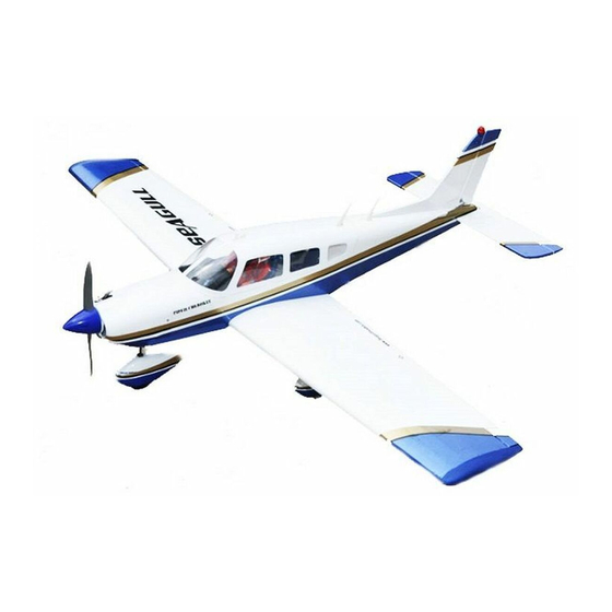
Specifications:
Wing span -------------------------59.8in (152cm)
Wing area --------------599.9sq.in (38.7sq dm)
Weight -------------------------------6.4 lbs (2.9kg)
Length ---------------------------46.4in (117.8cm)
Engine -------------.46 - .55 cu.in -----2-stroke.
.72 - .82cu.in -----4-stroke.
Radio ----------------- 4 channels with 5 servos.
1
Advertisement
Table of Contents

Related Manuals for Seagull Models CHEROKEE


Summary of Contents for Seagull Models CHEROKEE
- Page 1 www.seagullmodels.com MS:121 ASSEMBLY MANUAL “Graphics and specifications may change without notice”. Specifications: Wing span -------------------------59.8in (152cm) Wing area --------------599.9sq.in (38.7sq dm) Weight -------------------------------6.4 lbs (2.9kg) Length ---------------------------46.4in (117.8cm) Engine -------------.46 - .55 cu.in -----2-stroke. .72 - .82cu.in -----4-stroke. Radio ----------------- 4 channels with 5 servos.
-
Page 2: Kit Contents
. Flying the CHEROKEE is simply a joy. This instruction manual is designed to help you build a great flying aeroplane. Please read this manual thoroughly before starting assembly of your CHEROKEE . Use the parts listing below to identify all parts. -
Page 3: Hinging The Ailerons
www.seagullmodels.com HINGING THE AILERONS . KIT CONTENTS. Fuselage Note: The control surfaces, including the Canopy ailerons, elevators, and rudder, are Left wing panel prehinged with hinges installed, but Right wing panel the hinges are not glued in place. It Tail set is imperative that you properly Aluminum wing tube adhere the hinges in place per the... - Page 4 CHEROKEE Instruction Manual. Hinge. 4)Deflect the aileron and completely saturate each hinge with thin C/A glue. The ailerons front surface should lightly contact the wing during this procedure. Ideally, when the hinges are glued in place, a 1/64” gap or less will be maintained throughout the lengh of the aileron to the wing panel hinge line.
-
Page 5: Hinging The Elevators
www.seagullmodels.com WING TIP ASSEMBLY. Covering. Note: Work the aileron up and down several times to “work in” the hinges and Wing tip. check for proper movement. HINGING THE ELEVATORS. Glue the elevator hinges in place using the same techniques used to hinge the ailerons. 1) Attach the plastic wing tip to the wing. - Page 6 CHEROKEE Instruction Manual. Install plastic wing tip to wing end. INSTALL THE AILERONS CONTROL 3) Once the epoxy cures and use a covering HORN. iron to seal the covering on the wing and over the wing tip. 1) Locate the hardware necessary to install the control horns for the ailerons.
- Page 7 www.seagullmodels.com CONTROL HORN M3 SCREW. Epoxy. ALUMINUM WASHER 3mm. Wing M3 LOCK NUT ALUMINUM WASHER CONTROL HORN M3 Wing Aluminum Washer. Epoxy Horizontal 18mm Elevator. Stabilizer. Epoxy Aluminum Washer. M3 LOCK NUT Epoxy. Horizontal Elevator. Stabilizer. 18mm Aileron control horn . Elevator control horn.
-
Page 8: Engine Mount Installation
CHEROKEE Instruction Manual. INSTALL RUDDER CONTROL HORN. Repeat steps to install the rudder control horn as same as steps done for ailerons. 1 sets. Rudder control horn. 3x30mm. ENGINE MOUNT INSTALLATION. 1) Locate the items necessary to install the engine mount included with your model. . -
Page 9: Installing The Stopper Assembly
www.seagullmodels.com Vent tube. Fuel pick up tube. Fuel fill tube. INSTALLING THE STOPPER ASSEMBLY. 1) Using a modeling knife, carefully cut 3) Carefully bend the second nylon tube off the rear portion of one of the 3 nylon tubes up at a 45º angle. This tube is the vent tube. leaving 1/2”... -
Page 10: Installing The Fuselage Servos
CHEROKEE Instruction Manual. 10) Connect the lines from the tank to the engine and muffler. The vent line will connect to the muffler and the line from the clunk to the carburetor. 8) Use plywood template to hold in place the fuel tank with C/A glue to secure the fuel tank inside the fuselage. -
Page 11: Mounting The Engine
www.seagullmodels.com THROTTLE SERVO ARM INSTALLATION. MOUNTING THE ENGINE. 1) Position the engine with the drive washer Install adjustable servo connector in the servo (110mm) forward of the firewall as shown. arm as same as picture below: Loctite secure. Adjustable Servo connector. -
Page 12: Landing Gear Installation
CHEROKEE Instruction Manual. Linkage. Pushrod tube hole. 5) Slide the pushrod tube in the firewall and guide it through the fuel tank mount. Use 9) Move the throttle stick to the closed position medium C/A to glue the tube to the firewall and move the carburetor to closed. - Page 13 www.seagullmodels.com 2) While fitting the axle end of the nose landing 4) Fit the steering arm between the nylon gear leg into nose whell pants, slide wheel collar steering block. Insert the nose gear wire up onto axle followed by wheel and then another through the steering block and through the wheel collar.
- Page 14 CHEROKEE Instruction Manual. Trim and cut. Because of the size of the cowl, it may be nec- essary to use a needle valve extension for the high speed needle valve. Make this out of suf- ficient length 1.5mm wire and install it into the COWLING.
- Page 15 www.seagullmodels.com ELECTRIC POWER CONVERSION 1) Locate the items neccessary to install the electric power conversion included with your model. Epoxy. Balsa stick. - Model size: .35-.45 size models - Motor: 35mm 830 rev per volt - Propeller: 10x7 - ESC: 50A - Lipo Batteries: 4cell 3200mA Epoxy.
- Page 16 CHEROKEE Instruction Manual. Epoxy. 5.2mm. 110mm. 4) Locate the plywood battery tray to the fuselage. Tighten the screws using machine screws M3x15mm to secure the tray in position. Battery. Battery. M3 x 15mm. 5.2mm. Blind nut. 5) Attach the speed control to the side of the motor box using two-sided tape and tie wraps.
-
Page 17: Installing The Spinner
www.seagullmodels.com 6) Use a hobby knife and a covering iron to INSTALLING THE AILERON. open the cooling air exit in the bottom of the fuselage. Cutting the covering inside the Servos. opening and ironing the covering into the Small weight. fuselage will leave a clean look to the bottom of the fuselage as shown. - Page 18 CHEROKEE Instruction Manual. 4) Apply 2-3 drops of thin C/A to each of the mounting holes. Allow the C/A to cure without using accelerator. 5) Use dental floss to secure the connection so they cannot become unplugged. 6) Secure the servo to the aileron hatch using Phillips screwdriver and the screws provided with the servo.
- Page 19 www.seagullmodels.com 1) Mark the control wire where it crosses the servo arm hole. Bend at the mark. 2) Make a 90-degree bend at the mark and cut off the excess wire leaving 8mm past the bend. 9) Set the aileron hatch in place and use a Metal clevis.
-
Page 20: Main Landing Gear Installation
CHEROKEE Instruction Manual. Repeat the procedure for the other aileron servo. MAIN LANDING GEAR INSTALLATION. INSTALLING THE MAIN GEAR WIRES. Pencil. 1) Locate the items necessary to attach the main landing gear. M3x10mm. 2) Remove the covering from over two main landing gear mounting slots located in the bottom of the wing. -
Page 21: Installing The Horizontal Stabilizer
www.seagullmodels.com 5) Slide a wheel onto the axle. Prepare a second wheel collar with a machine screw and threadlock then install it on the axle to retain the wheel. M3x15mm. 4) Slide the wheel pant into position and insert the screw into the holes to secure the wheet pant to the landing gear mount as shown. - Page 22 CHEROKEE Instruction Manual. 7) When you are sure that everything is aligned correctly, mix up a generous amount of 30 Minute Epoxy. Apply a thin layer to the top and bottom of the stabilizer mounting area and to the stabilizer mounting platform sides in the fuselage.
- Page 23 www.seagullmodels.com 2) Slide the vertical stabilizer into the slot in the top of the fuselage. The rear edge of the stabilizer should be flush with the rear edge of the fuselage and the lower rudder hinge should engage the precut hinge slot in the lower fuselage.
- Page 24 CHEROKEE Instruction Manual. Elevator control horn. C/A glue. 3) Thread one clevis and M2 lock nut on 5) With both the rudder servo and rudder to each elevator control rod. Thread the horns centered, mark the rudder pushrod at the hole...
- Page 25 www.seagullmodels.com M2 lock nut . M2 clevis. 8mm. 7) Elevator and rudder pushrods assembly follow pictures below. Throttle. Elevator. Elevator control horn. Rudder. Rudder control horn. INSTALLATION PILOT. 8) Install servos arm to servos. Notice the position of the servo arms on the servos. See picture below.
-
Page 26: Install The Plastic Parts
CHEROKEE Instruction Manual. 1) A scale pilot is included with this ARF. The - Apply a bead of canopy glue around the inside Seagull Pilot included fitting well to the cockpit. edge of the canopy. Position the canopy onto (or you can order others scale pilot figures the hatch. - Page 27 www.seagullmodels.com 2) Position the plastic parts onto the canopy and fuselage and apply C/A glue and hold the plastic parts secure until the glue fully cures. Please see pictures below. C/A glue. C/A glue. C/A glue. 2mm. 50mm. C/A glue. Epoxy.
-
Page 28: Apply The Decals
CHEROKEE Instruction Manual. Epoxy. 1.5mm. APPLY THE DECALS. 1) If all the decals are precut and ready to stick. Please be certain the model is clean and free from oily fingerprints and dust. Position C/A glue. decal on the model where desired, using the photos on the box and aid in their location. - Page 29 www.seagullmodels.com BALANCING. ATTACHMENT WING-FUSELAGE. Attach the aluminium tube into fuselage. 1) It is critical that your airplane be balanced correctly. Improper balance will cause your plane to lose control and crash. THE CENTER OF GRAVITY IS LOCATED 80 MM BACK FROM THE LEADING EDGE OF THE WING AT THE WING ROOT.
-
Page 30: Control Throws
CHEROKEE Instruction Manual. CONTROL THROWS. Ailerons: 10mm - 12mm up. 10mm - 12mm down. 80mm. Elevator: 10mm - 12mm up. 10mm - 12mm down. Rudder: 20mm - 25mm left. 20 mm - 25mm right. FLIGHT PREPARATION. D) Check the throttle. Moving the throttle... -
Page 31: Preflight Check
2) Check every bolt and every glue joint and high rate settings. in the CHEROKEE to ensure that everything is tight and well bonded. 7) Check the receiver antenna. It should be fully extended and not coiled up inside the 3) Double check the balance of the air- fuselage.
Need help?
Do you have a question about the CHEROKEE and is the answer not in the manual?
Questions and answers