Table of Contents
Advertisement
WWW.SEAGULLMODELS.COM
A S S E M B L Y
M A N U A L
" Graphics and specifications may change without notice " .
Code : SEA255
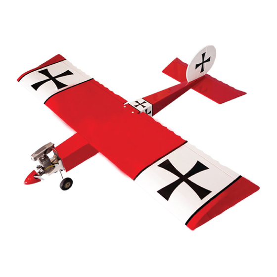
Specifications:
Wingspan---------------70.9 in (180 cm).
Wing area---------------1033.2 sq.in (66.7 sq.dm).
Weight-------------------7.7 lbs (3.5 kg).
Length-------------------57.8 in (146.8 cm).
Engine-------------------10cc - 15cc gasoline
----------------------------.60 -.91 glow engine
----------------------------1200-1500 Watt Brushless Motor
Radio---------------------4 channels with 5 servos.
Electric conversion: Optional.
www.seagullmodels.com
1
Advertisement
Table of Contents

Related Manuals for Seagull Models CLASSIC UGLY STICK


Summary of Contents for Seagull Models CLASSIC UGLY STICK
- Page 1 WWW.SEAGULLMODELS.COM A S S E M B L Y M A N U A L “ Graphics and specifications may change without notice “ . Code : SEA255 Specifications: Wingspan---------------70.9 in (180 cm). Wing area---------------1033.2 sq.in (66.7 sq.dm). Weight-------------------7.7 lbs (3.5 kg). Length-------------------57.8 in (146.8 cm).
-
Page 2: Kit Contents
The motor mount has been fit- ted and the hinges are pre-installed. Flying the CLASSIC UGLY STICK is simply a joy. This instruction manual is designed to help you build a great flying aeroplane. Please read this manual throughly before starting assembly of your CLASSIC UGLY STICK . -
Page 3: Hinging The Aileron
WWW.SEAGULLMODELS.COM HINGING THE AILERON. KIT CONTENTS. Note : The control surfaces, including the ai- SEA255 CLASSIC UGLY STICK lerons, elevators, and rudder, are prehinged SEA25501 Fuselage with hinges installed, but the hinges are not SEA25502 Wing set glued in place. It is imperative that you prop-... - Page 4 CLASSIC UGLY STICK Instruction Manual. 4) Deflect the aileron and completely satu- 7) Repeat this process with the other wing rate each hinge with thin C/A glue. The ailer- panel, securely hinging the aileron in place. ons front surface should lightly contact the wing during this procedure.
-
Page 5: Wing Assembly
WWW.SEAGULLMODELS.COM WING ASSEMBLY. Please see below pictures. INSTALLING THE AILERON SERVOS. Epoxy. Attach the aluminum tube into wing. Servos Small weight Thread 1) Install the rubber grommets and brass collets onto the aileron servo. Test fit the servo into the aileron servo mount. Because the size of servos differ, you may need to adjust the size of the precut openingin the mount. - Page 6 CLASSIC UGLY STICK Instruction Manual. 4) Tape the servo lead to the wing to prevent it from falling back into the wing. Plastic tape. 5) Reinstall the servo into the servo mount and secure the servo inplace using the wood screws provided with you radio system.
- Page 7 WWW.SEAGULLMODELS.COM AILERON PUSHROD HORN Servo arm. INSTALLATION. Please see below pictures. Snap keeper. Nylon Snap keeper. Hex Nut. Fuel tubing. Use a felt tip pen to mark the wire where it crosses the hole. Use a pair of pliers to put a shrp 90-degree bend in the wire at the mark.
-
Page 8: Installing The Fuselage Servos
CLASSIC UGLY STICK Instruction Manual. THROTTLE SERVO ARM INSTALLATION. Install adjustable servo connector in the servo arm as same as picture below: Adjustable servo connector. Loctite secure. Servo arm. Wing bolt. Throttle servo arm. INSTALLING THE FUSELAGE SERVOS. Because the size of servos differ, you INSTALLING THE RECEIVER SWITCH. - Page 9 WWW.SEAGULLMODELS.COM Switch. INSTALLING THE ENGINE SWITCH. Trim and cut. Switch. Vent tube. Fuel pick up INSTALLING THE STOPPER ASSEMBLY. Fuel fill tube. 1) Using a modeling knife, carefully cut off the rear portion of one of the 3 nylon tubes leaving 1/2” protruding from the 3) Carefully bend the second nylon tube up rear of the stopper.
-
Page 10: Fuel Tank Installation
CLASSIC UGLY STICK Instruction Manual. 5) With the stopper assembly in place, the weighted pick-up should rest away from the rear of the tank and move freely inside the tank. The top of the vent tube should rest just below the top of the tank. It should not touch Ignition Module. -
Page 11: Engine Mount Installation
WWW.SEAGULLMODELS.COM Blow through one of the lines to ensure the fuel lines have not become kinked inside the fuel tank compartment. Air should flow through easily. ENGINE MOUNT INSTALLATION. 1) Locate the items necessary to install the engine mount included with your 140mm model. - Page 12 CLASSIC UGLY STICK Instruction Manual. 6) Connect the Z-bend in the 450mm throttle pushrod to the outer hole of the carburetor arm. 7) Slide the throttle pushrod wire into the tube. Position the engine between the mounts. Use four M4x30mm machine screws to secure the engine to the mount as shown.
- Page 13 WWW.SEAGULLMODELS.COM ELECTRIC POWER CONVERSION. 1) Locate the items neccessary to install the electric power conversion included with your model. 4mm. 4mm. - Motor : .60 - Propeller: 14x 8 ~ 16x10 - ESC: 60A - 5S-7S Lipo 2) Attach the electric motor box to the firewall suitable with the cross lines drawn on the electric motor box and fire- Blind nut.
-
Page 14: Installing The Spinner
CLASSIC UGLY STICK Instruction Manual. Speed control. Tie wraps. 3x15mm. Battery. INSTALLING THE SPINNER. -
Page 15: Installing The Main Landing Gear
INSTALLING THE MAIN LANDING GEAR. NOTE : You must now decide if you will assemble the Classic Ugly Stick with tri- cycle landing gear or as a tail dragger. If you are assembling as a tail dragger, please skip the nose gear installation steps and mount the main gear to the FORWARD mounting location. -
Page 16: Nose Gear Installation
CLASSIC UGLY STICK Instruction Manual. NOSE GEAR INSTALLATION. Please see below pictures Collar. M4x20mm. Collar. M4x20mm. -
Page 17: Hinging The Elevators
WWW.SEAGULLMODELS.COM HINGING THE ELEVATORS. Glue the elevator hinges in place using the same techniques used to hinge the ai- lerons. Steering arm. HORIZONTAL STABILIZER. 1) Using a ruler and a pen, locate the center- line of the horizontal stabilizer, at the trail- ing edge, and place a mark. - Page 18 CLASSIC UGLY STICK Instruction Manual. 4) With the stabilizer held firmly in place, use a pen and draw lines onto the stabilizer Knife. where it and the fuselage sides meet. Pen. 7) When you are sure that everything is aligned correctly, mix up a generous amount of 30 Minute Epoxy.
-
Page 19: Vertical Stabilizer Installation
WWW.SEAGULLMODELS.COM 3) Remove the stabilizer. Using a modeling knife, remove the covering from below the lines you drew. VERTICAL STABILIZER Knife. INSTALLATION. 1) Slide the vertical stabilizer into the slot in the top of the fuselage. The rear edge of the stabilizer should be flush with the rear edge of the fuselage and the lower rudder hinge should engage the precut hinge slot in the... - Page 20 CLASSIC UGLY STICK Instruction Manual. 5) When you are sure that everything is aligned correctly, mix up a generous amount of 30 Minute Epoxy. Apply a thin layer to the mounting slot in the top of the fuselage and to the sides and bottom of the vertical sta- bilizer mounting area.
- Page 21 WWW.SEAGULLMODELS.COM 3) Hold the rudder in place and mark it ELEVATOR - RUDDER PUSHROD where the music wire will enter. When HORN INSTALLATION. you are happy with the fit, fill the hole with epoxy and use CA to glue in the 1) Locate items necessary to install eleva- rudder hinges.
- Page 22 CLASSIC UGLY STICK Instruction Manual. Rudder pushrod. M2 clevis. Hex nut. Fuel tubing. Elevator pushrod. INSTALLING BATTERY - RECEIVER. 1) Plug the five servo leads and the switch lead into the receiver. Plug the battery pack lead into the switch also.
-
Page 23: Control Throws
WWW.SEAGULLMODELS.COM 2) Mount the wing to the fuselage. Using a couple of pieces of masking tape, place 100 mm them on the bottom of the wing 100mm back from the leading edge of the wing at the wing root. 3) With the model upright, place your fingers on the masking tape and carefully lift the plane. - Page 24 CLASSIC UGLY STICK Instruction Manual.
-
Page 25: Flight Preparation
A) Plug in your radio system per the 2) Check every bolt and every glue manufacturer’s instructions and turn joint in the CLASSIC UGLY STICK everything on. to ensure that everything is tight and well bonded.
Need help?
Do you have a question about the CLASSIC UGLY STICK and is the answer not in the manual?
Questions and answers