Table of Contents
Advertisement
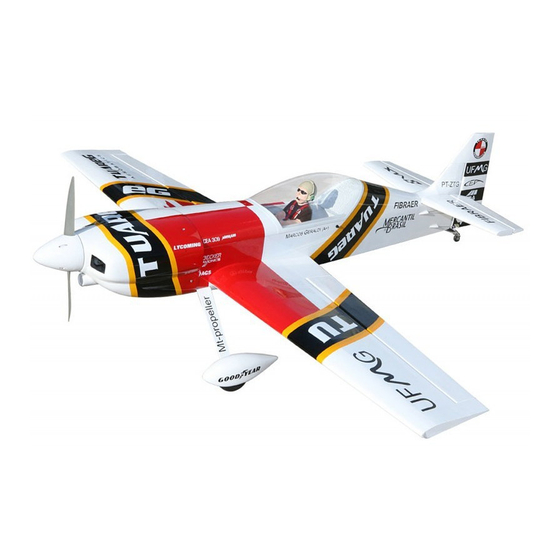
MS:167
ASSEMBLY MANUAL
"Graphics and specifications may change without notice".
Specifications:
Wing span ------------------------------66.9in (170cm).
Wing area -----------------764.2sq.in (49.3sq dm).
Weight ------------------------10.6lbs (4.8kg).
Length ------------------------------58.7in (149.0cm).
Engine ------------------ 0.91-1.2cu.in ----2-4-stroke.
Radio -------------------4 channels with 6 servos.
Electric conversion: optional
Advertisement
Table of Contents

Subscribe to Our Youtube Channel
Related Manuals for Seagull Models Mehari Aerobatics CEA-309


Summary of Contents for Seagull Models Mehari Aerobatics CEA-309
- Page 1 MS:167 ASSEMBLY MANUAL “Graphics and specifications may change without notice”. Specifications: Wing span ------------------------------66.9in (170cm). Wing area -----------------764.2sq.in (49.3sq dm). Weight ------------------------10.6lbs (4.8kg). Length ------------------------------58.7in (149.0cm). Engine ------------------ 0.91-1.2cu.in ----2-4-stroke. Radio -------------------4 channels with 6 servos. Electric conversion: optional...
-
Page 2: Kit Contents
CEA-309 MEHARI AEROBATICS INTRODUCTION. Thank you for choosing the CEA-309 MEHARI AEROBATICS ARTF by SEAGULL MODELS COMPANY LTD. The CEA-309 MEHARI AEROBATICS was designed with the intermediate/ advanced sport flyer in mind. It is a semi scale airplane which is easy to fly and quick to assemble. -
Page 3: Hinging The Aileron
www.seagullmodels.com HINGING THE AILERON . CONTENTS.TS Note: The control surfaces, including the Fuselage ailerons, elevators, and rudder, are Wing Set Tail Set prehinged with hinges installed, but Cowling the hinges are not glued in place. It Main Landing Gear is imperative that you properly Wing Tube adhere the hinges in place per the Hardware Set... -
Page 4: Hinging The Elevator
Instruction Manual. CEA-309 MEHARI AEROBATICS Hinge. 4) Deflect the aileron and completely 5) Turn the wing panel over and deflect the saturate each hinge with thin C/A glue. The aileron in the opposite direction from the ailerons front surface should lightly contact the opposite side. -
Page 5: Hinging The Rudder
www.seagullmodels.com HINGING THE RUDDER. INSTALL ELEVATOR CONTROL HORN. Glue the rudder hinges in place using the Install the elevator control horn using the same techniques used to hinge the ailerons. same method as same as the aileron control horns. Hinge. Fiberglass control horn Position the Control horn on the Aileron and use 30-minute Epoxy... -
Page 6: Installing The Stopper Assembly
Instruction Manual. CEA-309 MEHARI AEROBATICS Epoxy. INSTALLING THE STOPPER ASSEMBLY. Rudder control horn. 1) Using a modeling knife, carefully cut off the rear portion of one of the 3 nylon tubes leaving 1/2” protruding from the rear of the stopper. This will be the fuel pick up tube. 2) Using a modeling knife, cut one length of silicon fuel line. -
Page 7: Fuel Tank Installation
www.seagullmodels.com 7) Slide the fuel tank into the fuselage. Guide the lines from the tank through the hole in the firewall. Fuel tank. Vent tube. Fuel pick up tube. Fuel fill tube. 8) Use plywood template to hold in place 3) Carefully bend the second nylon tube the fuel tank with C/A glue to secure the fuel up at a 45º... -
Page 8: Installing The Switch
Instruction Manual. CEA-309 MEHARI AEROBATICS Elevator servo arm. Throttle servo arm. Rudder servo arm. INSTALLING THE SWITCH. Blow through one of the lines to en- Install the switch into the precut hole in the sure the fuel lines have not become kinked side, in the fuselage. -
Page 9: Mounting The Engine
www.seagullmodels.com MOUNTING THE ENGINE. 1) Position the engine with the drive washer (145mm) forward of the firewall as shown. Pushrod tube hole. 5) Slide the pushrod tube in the firewall and guide it through the fuel tank mount. Use medium C/A to glue the tube to the firewall and the fuel tank mount. - Page 10 Instruction Manual. CEA-309 MEHARI AEROBATICS 3) You have to trim each axle using a tool cutting and cut-off wheel. Caution when cutting the axles and wear protective goggles. 9) Move the throttle stick to the closed position 4) Slide the collar to the axle and setscrew and move the carburetor to closed.
- Page 11 www.seagullmodels.com 6) Slide the threaded end of the axle through the hole in the bottom of the landing gear leg. Use a washer and locknut to tighten Repeat steps as above to attach remain- the axle to the landing gear. Make sure to use ing wheel pants to the landing gear.
- Page 12 Instruction Manual. CEA-309 MEHARI AEROBATICS 2) While keeping the back edge of the COWLING. cowl flush with the marks, align the front of 1)Slide the fiberglass cowl over the engine the cowl with the crankshaft of the engine. The and line up the back edge of the cowl with the front of the cowl should be positioned so the marks you made on the fuselage then trim and crankshaft is in nearly the middle of the cowl...
- Page 13 www.seagullmodels.com 3) Attach the motor to the front of the electric ELECTRIC POWER CONVERSION. motor box using four 3mm blind nut, four M3x15mm hex head bolts to secure the motor. 1) Locate the items neccessary to install the Please see picture shown. electric power conversion included with your model.
-
Page 14: Installing The Spinner
Instruction Manual. CEA-309 MEHARI AEROBATICS 5) Attach the speed control to the side of the M3x15mm. motor box using two-sided tape and tie wraps. Connect the appropriate leads from the speed control to the motor. Make sure the leads will not interfere with the operation of the motor. -
Page 15: Installing The Aileron - Flap Servos
www.seagullmodels.com INSTALLING THE AILERON - FLAP SERVOS. 4) Apply 2-3 drops of thin C/A to each of the mounting holes. Allow the C/A to cure without using accelerator. Servos. Small weight. Thread. Because the size of servos differ, you may need to adjust the size of the precut open- 5) Use dental floss to secure the connection ing in the mount. - Page 16 Instruction Manual. CEA-309 MEHARI AEROBATICS 8) A string has been provided in the wing to pull the aileron lead through to the wing root. Remove the string from the wing at the servo location and use the tape to attach it to the servo extension lead.
-
Page 17: Installing The Horizontal Stabilizer
www.seagullmodels.com AILERON PUSHROD HORN INSTALLATION M3 clevis. M3 lock nut. 100mm. Wing. M3 lock nut. Aileron. 60mm. Wing Flap Wing Flap Repeat the procedure for the other aileron servo. 2) Using a modeling knife, carefully remove INSTALLING THE HORIZONTAL STABILIZER. the covering at mounting slot of horizontal sta- bilizer ( both side of fuselage). - Page 18 Instruction Manual. CEA-309 MEHARI AEROBATICS 7) When you are sure that everything is 4) With the stabilizer held firmly in place, aligned correctly, mix up a generous amount use a pen and draw lines onto the stabilizer of 30 Minute Epoxy. Apply a thin layer to the where it and the fuselage sides meet.
- Page 19 www.seagullmodels.com 4) When you are sure that everything is aligned correctly, mix up a generous amount of Fill epoxy. Flash 30 Minute Epoxy. Apply a thin layer to the mounting slot and to bottom of the vertical sta- bilizer mounting area. Apply epoxy to the bot- tom and top edges of the filler block and to the lower hinge also.
- Page 20 Instruction Manual. CEA-309 MEHARI AEROBATICS 3) Thread one clevis and M3 lock nut on to each elevator control rod. Thread the horns on until they are flush with the ends of the con- trol rods. 4) Elevator and rudder pushrods assembly as pictures below.
- Page 21 www.seagullmodels.com INSTALLATION PILOT AND CANOPY. 1) Locate items necessary to install pilot, cockpit panel, and canopy. 3x25 mm. M2x6mm. 2) A scale pilot is included with this ARF. The Seagull Pilot included fitting well to the cockpit. (or you can order others scale pilot figures made by Seagull factory.
-
Page 22: Apply The Decals
Instruction Manual. CEA-309 MEHARI AEROBATICS C/A glue. Battery. 4) Position the canopy onto the fuselage. Trace around the canopy and onto the fuselage using a felt-tipped pen. C/A glue. ATTACHMENT WING-FUSELAGE. Attach the aluminium tube into fuselage. M2x6mm. APPLY THE DECALS. Wing tube. - Page 23 www.seagullmodels.com Accurately mark the balance point on the top of the wing on both sides of the fuselage. The balance point is located 110 mm back from the leading edge of the wing at the wing root. This is the balance point at which your model should balance for your first flights.
-
Page 24: Control Throws
Instruction Manual. CEA-309 MEHARI AEROBATICS 3) When the elevator, rudder and aileron CONTROL THROWS. control surfaces are centered, use a ruler and check the amount of the control throw in each 1) We highly recommend setting up the surface. The control throws should be CEA-309 MEHARI AEROBATICS using the measured at the widest point of each sur- control throws listed at right. -
Page 25: Flight Preparation
www.seagullmodels.com PREFLIGHT CHECK. FLIGHT PREPARATION. 1) Completely charge your transmitter Check the operation and direction of the and receiver batteries before your first day of elevator, rudder, ailerons and throttle. flying. 2) Check every bolt and every glue joint A) Plug in your radio system per the in the CEA-309 MAHRI AEROBATICS to en- manufacturer's instructions and turn every- sure that everything is tight and well bonded.
Need help?
Do you have a question about the Mehari Aerobatics CEA-309 and is the answer not in the manual?
Questions and answers